Search results
Query: antennas 6m
Links: 32 | Categories: 1
Categories
-
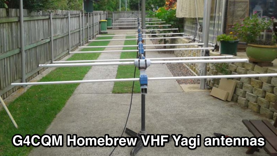 Homebrew VHF Yagi 50MHz 144MHz 432MHz 1296MHz 2320MHz 6M 2M 70CM 23CM 13CM Yagis
 -
 The ARRL ANTENNA Vol 5 COMPENDIUM features an article detailing two portable 6-meter antennas: a 2-element quad and a 3-element Yagi with telescoping elements. The 2-element quad exhibits a measured gain of **4.2 dB** over a dipole, while the 3-element Yagi achieves **5.8 dB** over a dipole. Both designs prioritize ease of construction and rapid assembly/disassembly for portable operations. Specific dimensions are provided for a 3-element 6-meter quad using #14 bare copper wire. The reflector element diameter is 6.2958 meters, the driven element 6.125 meters, and the director 5.8547 meters. Element spacing is 0.9398 meters between reflector and driven, and 1.1684 meters between driven and director. The SWR is under _1.26:1_ from 50 to 50.4 MHz, with a feed point impedance of 48.75 -j0.13 Ohms at 50.2 MHz, suitable for direct 50 Ohm coax feeding with a current _balun_.
 -
 The BV6 50 MHz Yagis resource details the construction of two distinct Yagi antenna designs for the 6-meter band, specifically a 1-wavelength (1wl) model and a 2.1-wavelength (2.1wl) model. The 1wl Yagi, with a boom length of 5.850m, achieves a gain of **9.4 dBd**, while the 2.1wl Yagi, spanning 12.90m, boasts a gain of **11.9 dBd**. These designs adhere to a proven methodology for optimizing current slope and maintaining constant phase delay across parasitic elements, ensuring high gain per boom length and an _excellent pattern_. Both designs target a 50-ohm input impedance, facilitating straightforward feeding with a robust folded dipole. Final verification using NEC-II software confirmed the antennas' exceptional stacking capabilities, yielding stacking gains exceeding **5.8 dB** for a 2x2 array with minimal mutual detuning. The resource provides common mechanical data, including boom and element diameters, and specifies element lengths corrected for boom diameter. While the original _DUBUS Technik V_ publication contained incorrect element lengths, this resource provides the accurate dimensions for proper construction, emphasizing the use of readily available materials for cost-effective amateur radio deployment.
 -
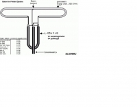 A 1:4 balun suitable for folded dipole antennas
 -
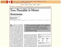 VE7CA reprint an interesting article taken from arrl antenna compendium. Two elegant practical and portable 6-meter gain antennas, a two-element quad and a tree-element Yagi antenna for 50 Mhz-6 meter band
 -
 This Magnetic Longwire Balun (MLB) makes it possible to efficiently use a coaxial lead-in cable with all forms of longwires, T-forms or other types of wire antennas, without the need for an antenna tuner.
 -
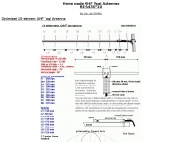 ON6MU Optimized 10 and 6 and 4 element UHF Yagi Antenna
 -
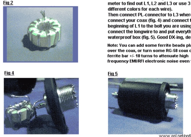 RF Choke to prevent hf currents on the feedline. This Magnetic Longwire Balun (MLB) makes it possible to efficiently use a coaxial lead-in cable with all forms of longwires, T-forms or other types of wire antennas, without the need for an antenna tuner.
 -
 The document details the optimization and construction of the _Maria Maluca_ antenna, a compact 6-band (20m-6m) directional beam. It presents a comparative analysis of shortwave antenna principles, highlighting the efficiency gains achieved by using an open feeder line and tuner as a resonant unit, contrasting this with the losses associated with traps or capacitive loads in multiband antennas. The resource specifically revisits an older South American 2-element design for 10, 15, and 20 meters, applying modern NEC-based software to develop a six-band version. Performance data is meticulously tabulated, showing impedance, free space gain, gain at 12m height, elevation angle, and front-to-back (F/B) ratio for each band from 20m through 6m. For instance, on 15m, the antenna achieves 5.1 dBd free space gain and 13.72 dB F/B ratio. The construction section provides practical guidance on element assembly using aluminum pipes and hose clamps, detailing the use of a heavy-duty glass fiber reinforced polyamide rod for electrical separation and bending strength. It also specifies the use of 450-ohm _Wireman_ line CQ 552 for the transmission line. The document includes diagrams for rod fixing, an air-wound balun, and a vertical elevation diagram for the 15m band, illustrating its DX qualification. It also discusses the antenna's suitability for portable and expedition operations, noting its compact transport dimensions (max 1.50m length, 12 lb weight) and quick assembly time (under 15 minutes). The author, Dipl.Ing. Helmut Oeller, DC6NY, is identified as a source for material kits.
 -
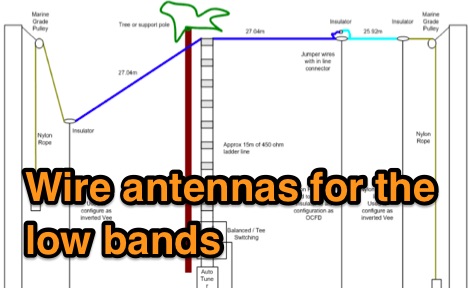 Experiments by G8JNJ on wire antennas for low bands. Based on these tests, conclude that for multiband (160 to 6m) operation, in a restricted area it is very difficult to beat a G5RV, especially the ZS6BK version.
 -
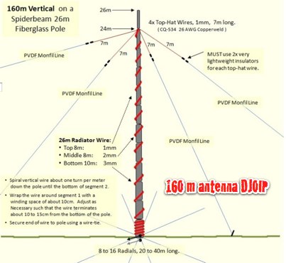 A vertical antenna for the top band, made with a 26m fiberglass spiderpole by DJ0IP
 -
 This Magnetic Longwire Balun (MLB) makes it possible to efficiently use a coaxial lead-in cable with all forms of longwires, T-forms or other types of wire antennas, without the need for an antenna tuner.
 -
 The PDF document, titled "J-Poles," presents various J-pole antenna designs covering the 50 MHz to 450 MHz frequency range. It includes construction details for several specific bands, such as a 6-meter J-pole, a 2-meter J-pole, and a 70-centimeter J-pole. The content outlines the fundamental principles of J-pole operation, including the quarter-wave radiator and half-wave matching stub. Each design features specific dimensions for elements like the radiator length, stub length, and spacing, often expressed in inches. The document also discusses feeding arrangements and impedance matching considerations inherent to J-pole antennas. It provides practical guidance for homebrewing these antennas using common materials like copper pipe or wire elements. The resource offers insights into the advantages of J-poles, such as their omnidirectional pattern and ease of construction, making it a practical reference for radio amateurs interested in VHF/UHF antenna projects.
 -
 The **70cm Moxon Beam** project outlines the construction and testing of a compact, directional antenna for the 432 MHz band. G3XBM recounts his early 1980s experience with a 4W FM321 transceiver and a Jaybeam 48-element TV antenna, which provided a baseline for his later UHF antenna experiments. This project focuses on a simpler, yet effective, design for local and regional contacts, emphasizing ease of construction and practical field results over complex theory. The article details the specific dimensions and materials used for the Moxon rectangle, including 6mm diameter aluminum tubing for the elements and a PVC boom. G3XBM notes that the antenna was built for portable use, making it lightweight and easily deployable for field operations. The feedpoint impedance was measured at 50 ohms, ensuring a direct match without the need for an external tuner, which simplifies setup. Performance tests included comparisons against a commercial 5-element Yagi, revealing that the Moxon provided comparable forward gain and an excellent front-to-back ratio, crucial for reducing local QRM. The author's observations confirm the Moxon's reputation as a robust performer for its size, suitable for both fixed and portable 70cm operations.
 -
 By Guy, de ON6MU, At VHF, both the 1/4-wavelength monopole and the 5/8-wavelength monopole antennas are widely used.
 -
 DK7ZB provides detailed construction plans for Moxon antennas utilizing tapered aluminum tubing, specifically outlining dimensions for 50 MHz, 28 MHz, 24 MHz, and 21 MHz bands. The resource emphasizes maintaining specific taper lengths for optimal performance and describes a tuning method involving symmetrical element shifts. It also addresses stacking considerations, noting that two Moxons can be stacked 1m apart with a 90° rotation to avoid severe detuning, unlike co-planar mounting. Performance figures for the 50-MHz Moxon include a gain of **4.1 dBd** and a front-to-back ratio of _30 dB_. The construction utilizes copper fittings for element connections, with a recommendation to varnish edges against corrosion. The page features images of built antennas by _DK8UH_ and VK2QO, illustrating practical implementations for the 6-meter and 10-meter bands, respectively.
 -
 This article compares two commercial vertical antennas for the 4-meter amateur radio band: the Watson WVB-70 half-wave and the Sirio CX4-71. The Watson measures 2.03m in length, costs around £40, and exhibited adequate performance but required additional waterproofing after rain affected its VSWR readings. The longer Sirio CX4-71 (3.02m) performed noticeably better, delivering signals approximately 2 S-points stronger than the Watson. The Sirio demonstrated high build quality, a stable 1.2-1.4:1 VSWR, and weather resilience, though minor VSWR fluctuations were observed during rain and frost. Both antennas are half-wave designs requiring no ground plane radials.
 -
 The X80 multi-band HF vertical antenna, a commercial iteration of the Rybakov design, exhibits a physical length of 5.5 meters, or approximately 18 feet, and is constructed from aluminum tubing. It operates as a non-resonant vertical, requiring an external antenna tuner for impedance matching across its intended operating frequencies. The antenna's design incorporates a 1:4 UNUN at its base, facilitating a nominal 50-ohm feed point impedance for the coaxial cable. Performance observations indicate effective operation on 40 meters, 20 meters, 15 meters, and 10 meters, with reduced efficiency on 80 meters and 160 meters due to its relatively short electrical length for these lower bands. Comparative analysis with a G5RV dipole and a half-wave end-fed antenna reveals the X80 offers a lower take-off angle, beneficial for DX contacts, particularly on the higher HF bands. Field tests conducted with an Icom IC-706MKIIG transceiver and an LDG AT-100ProII autotuner demonstrate the X80's ability to achieve acceptable SWR across 80m through 10m. The antenna's compact footprint and ease of deployment make it suitable for restricted spaces or portable operations, though its performance on 80 meters is noted as a compromise compared to full-size resonant antennas.
 -
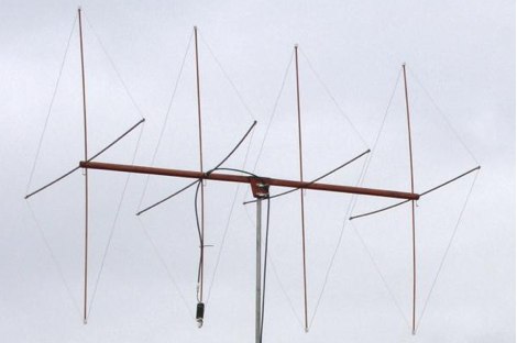 Article by G4AON about a 4 and 2 Element Quad Antennas for the 6m band
 -
 This Magnetic Longwire Balun (MLB) makes it possible to efficiently use a coaxial lead-in cable with all forms of longwires, T-forms or other types of wire antennas, without the need for an antenna tuner.
 -
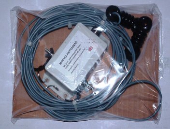 M0CVO Antennas, amateur radio antennas for fixed station or portable operations, HF/6m all are catered for. The antennas produced by us are all manufactured by Nigel Booth, M0CVO
 -
-
 Documents the OC1I and OC6I IOTA DXpeditions to Peru, specifically highlighting operations from SA-098 (Isla La Leona) and SA-076 (Isla Lobos de Afuera). The OC1I team logged over **8000 QSOs** from SA-076, while OC6I made 1400 QSOs from SA-098, despite challenging propagation conditions. The resource details the equipment used, including an _IC-7000_, an IC-706mkIIG, and a TS-440SAT, along with various antennas such as a 160m dipole, FD4, G5RV, and a multi-band vertical for 17m, 20m, 30m, and 40m. The DXpedition dates are specified: OC6I operated from SA-098 between December 28 and December 30, while OC1I was active from SA-076 from January 2 to January 7. Both operations are confirmed as valid for IOTA credit. The page also includes a video link for the OC6I operation and a photo gallery from the DXpedition. Feedback is welcomed, and the webmaster is identified as Bodo Fritsche, DL3OCH.
 -
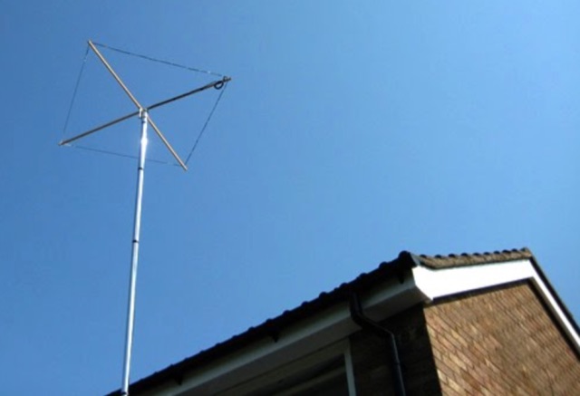 The Homebase-10 is a wire halo antenna for 10m built with DIY store parts, effective despite its small size. Includes a dual-band version for 10m and 6m with gain around 0 to -2dBd, near omnidirectional pattern, and horizontal polarization. Overview based on a 2008 Practical Wireless article.
 -
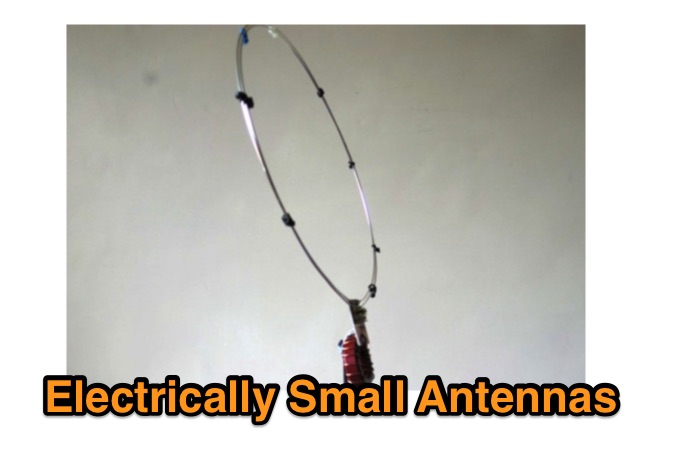 An antenna system is electrically small if it's enclosing sphere is <λ/2π. So a 10m band antenna of under 1.6m long qualifies.
 -
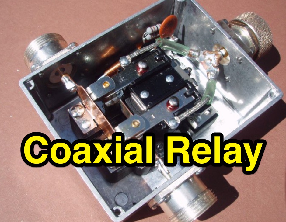 Build a SPDT coaxial relay that can be used as a main Transmit/Receive relay or an A-B switch to select between two different 6m antennas
 -
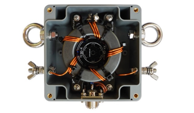 This Guide helps you to build the 1:2 BalUn 600 Watts DIY kit step by step. If a delta-loop or quad-loop antenna is powered with a coax cable from the transceiver it is necessary to use a 1:2 BalUn. This 1:2 BalUn uses a symmetrical 1:2 impedance transformer.
 -
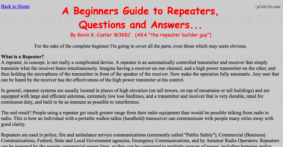 Explains the fundamental purpose of a repeater, detailing how these automated relay stations overcome distance and terrain limitations for VHF/UHF communications. It traces the historical development from early Bell Telephone Labs "relay" stations in 1922 to Art Gentry, W6MEP's, pioneering K6MYK amateur radio repeater in the mid-1950s, which remains active today. The resource clarifies the distinction between simplex and duplex operation, including the unique function of a "parrot repeater" for single-frequency recording and playback. Delving into the internal workings, the guide breaks down a repeater into its core components: the antenna system, feedline (often _Heliax_ or hardline for minimal loss), duplexer, receiver, transmitter, and controller. It emphasizes the critical role of the duplexer in preventing receiver desensitization by isolating transmit and receive signals, even with distinct frequencies. The discussion highlights the importance of high-performance, durable antennas and low-loss feedlines, citing examples of equipment installed in the 1960s and 1970s that are still in perfect working order. Operating a repeater is also covered, with an explanation of frequency offset (e.g., the 600 kHz standard for 2 meters) and the function of _CTCSS_ (PL tone) for access. It outlines standard input/output offsets for various bands, from 6 meters to 23 centimeters, while noting regional variations. The guide also touches on features like autopatch and Digital Voice Recorders (DVRs), providing a solid foundation for understanding repeater technology and usage.
 -
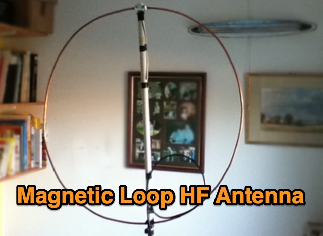 An homebrew HF Magnetic loop made with 2m length of 6mm diameter copper pipe formed into a near circle as the low loss inductor, a short length of coax as a capacitor,a short length of mains cable, again as a fixed tuned capacitor, a tunable 365pF air spaced capacitor, and a small Jackson C804 airspaced variable with a small 3-35pF trimmer in parallel
 -
 EA4EOZ details the construction and testing of 50 MHz traps, a critical component for multiband antenna designs. The project addresses the challenge of sourcing high-voltage capacitors suitable for trap applications, exploring alternatives to expensive doorknob capacitors. The author successfully fabricated a capacitor using 1.6mm double-sided FR-4 PCB material, achieving a capacitance density of **2.6 pF/cm2**. Utilizing the _VE6YP calculator_, specific L and C values of 30 pF and 0.31 uH were determined for a 2cm diameter coil. Both the FR-4 PCB trap and a coaxial cable trap, constructed from _RG-58_, were built and tuned to approximately 50 MHz using a spectrum analyzer. The coaxial cable trap demonstrated superior performance, exhibiting a notch nearly **20dB deeper** than the FR-4 version. This practical comparison provides insights into trap construction for experimental antennas, with the coaxial cable trap selected for an antenna project intended for operation at up to 100 watts.
 -
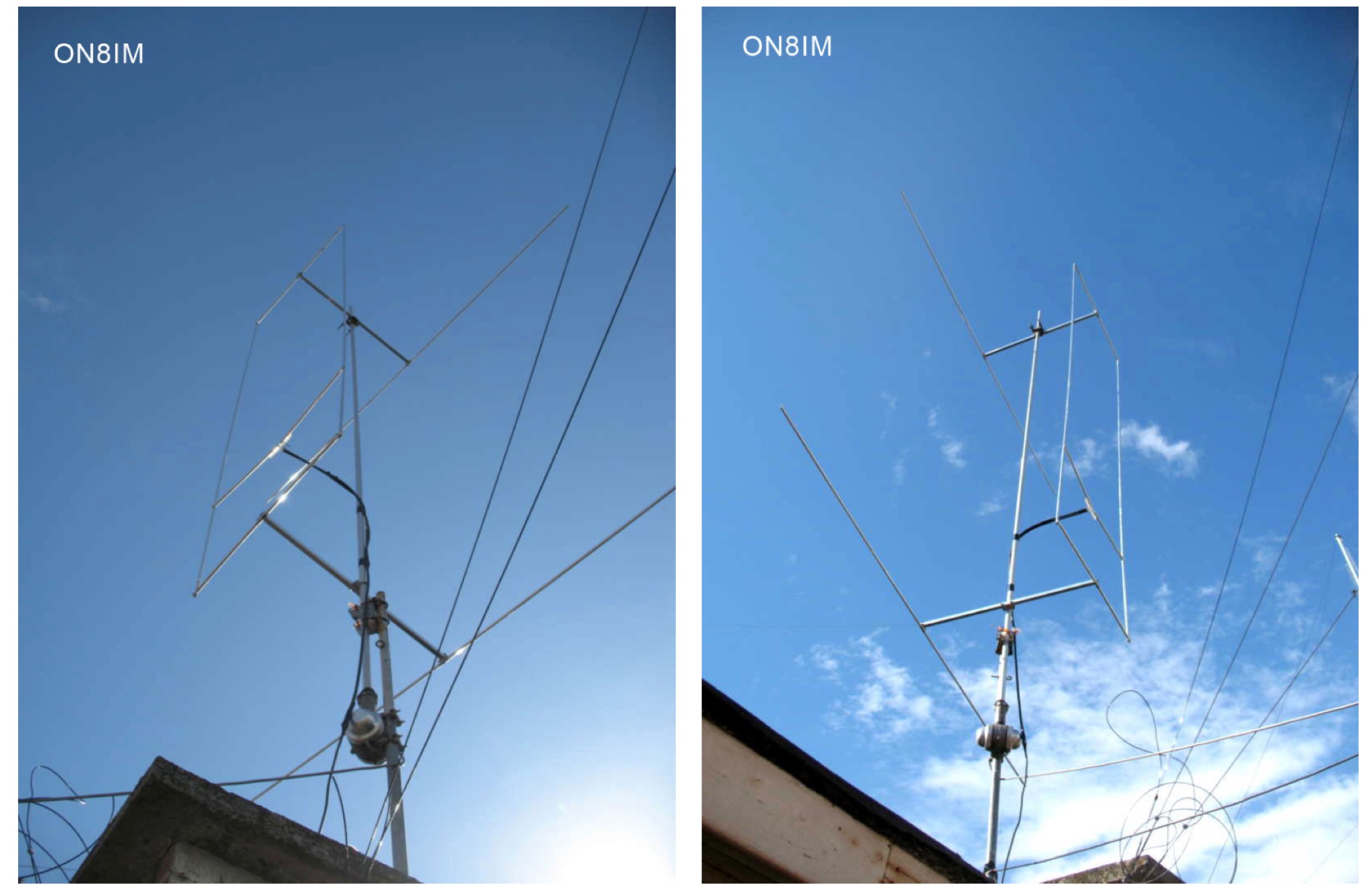 Explores the addition of a reflector to the traditional Hentenna design for 6m band, providing construction insights, performance comparisons, and modeling data
 -
 The Acom 1500 HF+6M Linear Amplifier is a high-quality and user-friendly amplifier that provides excellent performance and reliability. G6NHU, who previously owned an Acom 1000, upgraded to the Acom 1500 after nine years and has been using it for about eighteen months. Key features highlighted include the ability to connect three antennas internally, straightforward tuning process, robust construction that can handle high SWR, quiet operation, fast and quiet switching for efficient CW operation, and clean output signal even when driven hard. G6NHU highly recommends the Acom 1500 and states they would not hesitate to purchase another one in the future.