Search results
Query: antennas for 2 meters band
Links: 109 | Categories: 3
Categories
-
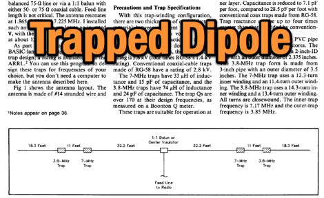 Build a space efficient trapped dipole antenna for 40-80-160 meter bands using RG-58 and PVC pipe. The document provides a brief guide on building a compact dipole antenna appropriate for the 40, 80, and 160-meter amateur radio bands. It explains the materials, building processes, and tuning methods required to provide best performance while preserving space. The paper also discusses theoretical elements of dipole antennas, such as impedance matching and feedline selection.
 -
 Demonstrates the construction of a **multi-band HF mobile antenna** utilizing a modified CB whip antenna base. The resource details the process of stripping a commercial CB whip, winding a new helical coil with 0.7mm insulated copper wire, and identifying tapping points for various HF bands. It emphasizes the importance of a rugged, slim design for mobile operation, discussing mechanical length, power handling (up to 200 watts), and coil diameter considerations. The article includes a graphic illustrating the antenna's operational principle, where sections of the helical coil are shorted from bottom to top to maintain efficiency and high Q. The resource presents a practical approach to achieving **band switching** without an external tuner, by manually adjusting tapping points on the coil. It provides a table with reference lengths in centimeters from the feedpoint for 7 MHz (40m) through 28.7 MHz (10m), including WARC bands. The author details mounting techniques, suggesting a Diamond bracket for secure attachment to a vehicle trunk, and stresses the critical role of proper grounding for optimal performance. The design allows for operation on 75m and 80m bands by adding a 110mm steel whip.
 -
-
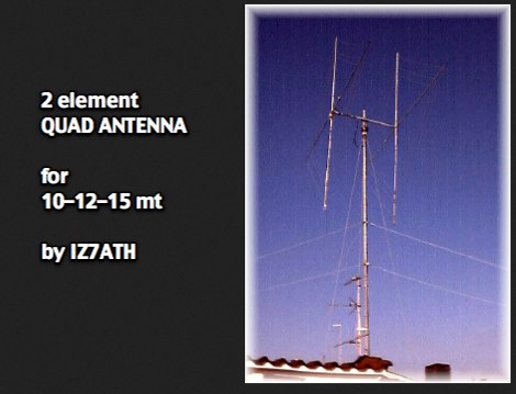 This resource provides comprehensive instructions for constructing a 2 element quad antenna specifically designed for the 10, 12, and 15 meter bands. The antenna features a diamond configuration, which offers improved gain compared to a square configuration. The author shares insights into the materials used, including a square-aluminum boom and bamboo poles, along with construction techniques that ensure durability and optimal performance. This project is ideal for amateur radio enthusiasts looking to create their own antennas at home. In addition to construction details, the author discusses the antenna's performance, noting its effectiveness even at a height of 8 meters. The quad antenna reportedly performs comparably to a 3 element yagi, with excellent SWR readings and strong signal reports from European stations. This project is suitable for beginners and offers a cost-effective solution for those interested in enhancing their amateur radio setup with a homemade antenna.
 -
 Demonstrates the construction of **magnetic loop antennas**, detailing both multi-turn and single-turn designs. It covers a 30-inch diameter multi-turn loop for 80 meters, based on a February 1996 QST article, and an octagon single-turn loop made from 15mm copper tube with a 4.8-meter circumference, operating from 7 MHz to 14 MHz. The document also presents a smaller 800mm diameter loop for 14 MHz to 28 MHz, emphasizing the importance of high-voltage tuning capacitors. Covers the design and construction of custom **butterfly capacitors** and piston capacitors, including a split stator capacitor with 140 pF capacitance and a 6000 Volt rating, and a butterfly capacitor with 5-65 pF and 7200 Volt rating. It explains why butterfly capacitors are preferred over split stator types for high power applications due to lower losses and direct series connection of rotors, reducing resistive losses from wiper contacts. Material recommendations include clear PVC for plates and brass or stainless steel for non-magnetic hardware. Addresses practical considerations such as feeding the loop with a shielded 1/5 Faraday loop made from RG213 or RG8 coax, achieving VSWR 1.1 across bands, and optimizing its placement 180° from the capacitor. It also discusses mechanical joint resistance, dissimilar metal oxidation prevention using Vaseline, and a simple method for determining radiation angle with a TL-light tube. The guide includes diagrams for rotor, stator, and end plate construction.
 -
 Low noise, receive only coax loop antennas for 160 - 10 meters HF bands
 -
 Base station and repeater antennas, mobile antennas, ,multi-band HF antennas , handheld transceivers, receiving and scanner antennas, power meters, swr meters, power supplies, coaxial switches
 -
 For radio amateurs considering homebrew antenna projects, this resource details several designs from WE6W, an experienced operator. It covers the construction and characteristics of a _160 Meter QRP Loop Antenna_ optimized for high voltage, along with standard and folded variations of the double bazooka antenna. The site also presents a unique Field Day antenna design and instructions for building a Sterba Curtain, a directional array known for its gain. Each design includes practical insights from the author's building experience. The author provides comparative data, such as the performance of a standard bazooka against a traditional dipole, offering real-world context for antenna selection. The Sterba Curtain section includes notes on its beamwidth and gain, crucial parameters for directional operation. These designs are suitable for hams looking to experiment with cost-effective, high-performance antennas for various bands and operating scenarios, from QRP on 160m to directional DXing with a Sterba Curtain, which can offer significant forward gain, often exceeding **10 dB**.
 -
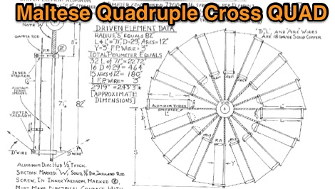 The Pfeiffer Maltese Quad Antenna System presents a unique approach to traditional quad antennas by utilizing a linear loading technique. This method effectively reduces the overall size of the antenna while maintaining its performance capabilities. Designed by Andrew Pfeiffer, the antenna's configuration resembles a Maltese cross, which not only enhances its structural integrity but also allows it to withstand challenging environmental conditions. This system is adaptable, offering various configurations from a 4-spreader Maltese Quad to a 16-spreader Maltese Quadruple-Cross, making it suitable for operators looking to optimize their setup without sacrificing efficiency. This antenna system is particularly versatile, covering multiple bands including 40, 20, 17, 12, and 10 meters. The design focuses on minimizing the physical footprint while ensuring effective signal transmission and reception. Amateur radio operators can benefit from the detailed plans available in the accompanying PDF, which outlines the construction process and specifications. Whether you're a seasoned DXer or a newcomer to the hobby, the Pfeiffer Maltese Quad Antenna System offers a practical solution for enhancing your station's capabilities.
 -
 The HB9ABX mobile HF antenna, developed by _Felix Meyer_, offers a high-performance alternative to commercial mobile antennas for 80 through 10 meters. Constructed from fiberglass rods and enamelled copper wire, this design incorporates a loading coil with multiple taps, allowing for band-specific tuning. The article provides detailed instructions for winding the coil, connecting the antenna elements, and integrating it with a vehicle's chassis ground. Field tests conducted at 100W consistently showed the HB9ABX antenna outperforming a HUSTLER mobile antenna by up to **10 dB** (1 S-point) and a YAESU ATAS-100/120 by **18 dB** (2-4 S-points) across distances from 5 km to 1000 km. The design emphasizes a robust ground connection and the use of an antenna tuner, such as an _MFJ-901B_, for optimal SWR on all bands, particularly 40 and 80 meters. Initial adjustment involves setting whip length and coil tap positions to achieve resonance without a tuner, followed by fine-tuning with the tuner during operation. Specific measurements are provided for checking resonance on 21.0 MHz and 14.2 MHz, with precise turn counts for the lower (79 turns) and upper (120 turns) antenna sections. Safety precautions for handling fiberglass dust are also highlighted.
 -

-
 Experimental omni-directional antennas for 6-meters band
 -
 Demonstrates the construction and on-air performance of the _NB6Zep_ antenna, a modified 20-meter Extended Double Zepp design optimized for multi-band operation from 40 through 10 meters. The resource covers basic design principles, including dimensions of 66 feet horizontal and 5 feet vertical elements, and specifies open ladder line or TV twin lead for the transmission line. It details material selection for low-cost wire antenna construction, such as 18 AWG wire for the legs and ceramic or plastic insulators, along with practical tips for soldering connections and insulating against moisture. The author, NB6Z, shares insights from extensive _EZNEC_ modeling to optimize the antenna's total length for a 40-meter half-wave dipole footprint and feed line length for direct tuner connection. The article presents field results, including successful _PSK31_ contacts from Oregon to the East Coast on 40 and 30 meters with 50 watts, even at a low height of 6 feet. It provides detailed performance characteristics for each band, noting the _NB6Zep_'s highest gain (over 3 dB) and sharp, medium-angle lobes on 20 meters, which yielded strong DX reports to locations like Korea, Japan, and Argentina. For 17 and 15 meters, it describes a butterfly-like pattern with broad lobes, while 12 and 10 meters exhibit narrow, directional lobes in an "X" configuration. The author also shares personal experiences operating successfully for over a decade in an antenna-restricted environment using the NB6Zep and other stealth wire antennas.
 -
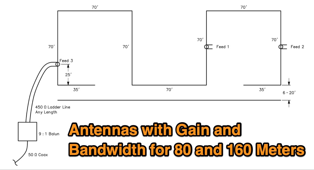 The Bruce array is a simple, often-forgotten wire antenna array that is advantageous for 80 and 160 meters, where typical gain antennas are very large. This bi-directional broadside vertical array is only 1\4 lambda high and does not require a ground system. It offers substantially greater SWR bandwidth than the half-square or bobtail curtain. A 4-element Bruce array used by N6LF showed a gain of about 4.6 dB compared to a 1\4 lambda vertical with 8 elevated radials, with a 2:1 SWR bandwidth greater than 400 kHz. The antenna is simple and its dimensions are flexible.
 -
 The KD6WD Moxon Antenna Project details the construction of 50-ohm two-element wire beam antennas, specifically Moxon rectangles, for the 10, 15, 17, and 20-meter bands. It utilizes AC6LA's software for critical measurement calculations (A-E) based on center frequency and wire size. Construction involves 16-gauge silver-coated copper wire, 16-foot telescoping fiberglass crappie fishing poles as spreaders in an "X" configuration, and various hub designs including aluminum tubing or PVC joints. A 1:1 current balun is used at the feedpoint, with wire nuts for connections, often achieving a 1:1 SWR across the design band. The project highlights practical applications, such as running a kilowatt into the antennas for greyline DX contacts, consistently yielding excellent signal reports. Comparisons to quad loops show 4 to 5 S-unit improvements in both receive and transmit. The Moxon design, according to L.B. Cebik's analysis, offers superior forward gain and front-to-back ratio among wire beams. The author notes a "DX-Vane" effect where a freely suspended Moxon automatically points to the strongest DX signal. Attempts at dual-band operation (17/20 meters) with a single feed were unsuccessful, reinforcing the Moxon's monoband nature, with EZNEC plots provided for a 17-meter Moxon at 30 feet.
 -
 EI7BA Multiband Cubical Quads projects, includes two elements quad antennas for 10 12 15 17 20 meters band. Performance considerations, detailed pictures and construction notes.
 -
 WB2VUO presents a practical examination of effective HF mobile antennas, focusing on the inherent efficiency challenges encountered on the lower bands, specifically 160, 80, and 40 Meters. The resource delves into the necessity of loading coils for mobile operation below 21 MHz, where full-sized antennas are impractical. It contrasts base-loaded and center-loaded designs, noting that base-loaded antennas are simpler for the average ham to construct but offer lower efficiency compared to center-loaded configurations. The author provides specific data for an 8-foot whip, detailing its electrical length and _radiation resistance_ across various HF bands, from **0.08 ohms** on 160 Meters to **16.1 ohms** on 12 Meters. This data highlights the extremely low radiation resistance on lower frequencies, which significantly impacts feedpoint impedance due to ground and feedline losses. The discussion includes practical considerations for feedpoint impedance, noting that a typical 8-foot whip on 10 Meters might present 30-45 ohms, allowing for acceptable SWR without an ATU. Construction sketches illustrate both base-loaded and center-loaded mobile antennas, with advice on material selection like galvanized steel for rugged bottom sections. The article also includes coil value charts from the _ARRL Mobile Manual_ for both base and center loading, emphasizing the importance of using large diameter wire to minimize losses and suggesting capacity hats to reduce coil inductance and improve performance on 160-40 Meters.
 -
-
 Vertical antennas for all HF bands, expecially 80 40 20 meters bands
 -
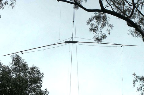
 Rigid Dipole antennas for 14 MHz band using PVC and Aluminium tubing
 -
-
 The **NW3Z** optimized wideband antenna designs, originally presented at Dayton 2001, detail Yagi configurations for the 20-meter, 15-meter, and 10-meter amateur radio bands. This resource provides access to the design files, likely containing critical parameters such as element spacing, element lengths, and boom dimensions, which are essential for replicating these directional antennas. The designs focus on achieving wide bandwidth, a desirable characteristic for contesters and DXers operating across a significant portion of each band. The content specifically references "nw3z-Antenna-DesignsDownload," indicating that the core information is available as a downloadable file, presumably in a format suitable for antenna modeling software or direct construction. Such files typically include **NEC models** or similar data, allowing for performance analysis and optimization before physical construction. The emphasis on "optimized wideband" suggests design considerations for SWR bandwidth and gain characteristics over a broader frequency range than typical narrow-band Yagis. The resource serves as a direct source for specific, proven antenna designs from a known amateur radio antenna designer, offering practical data for hams interested in building high-performance Yagi arrays for HF.
 -
 Manufacturer of communications antennas, bandpass filters, RF combiners, receiver multicouplers, diplexers, duplexers, RF connectors, RF circulators, RF isolators, RF couplers and SWR meters
 -
 The BV6 50 MHz Yagis resource details the construction of two distinct Yagi antenna designs for the 6-meter band, specifically a 1-wavelength (1wl) model and a 2.1-wavelength (2.1wl) model. The 1wl Yagi, with a boom length of 5.850m, achieves a gain of **9.4 dBd**, while the 2.1wl Yagi, spanning 12.90m, boasts a gain of **11.9 dBd**. These designs adhere to a proven methodology for optimizing current slope and maintaining constant phase delay across parasitic elements, ensuring high gain per boom length and an _excellent pattern_. Both designs target a 50-ohm input impedance, facilitating straightforward feeding with a robust folded dipole. Final verification using NEC-II software confirmed the antennas' exceptional stacking capabilities, yielding stacking gains exceeding **5.8 dB** for a 2x2 array with minimal mutual detuning. The resource provides common mechanical data, including boom and element diameters, and specifies element lengths corrected for boom diameter. While the original _DUBUS Technik V_ publication contained incorrect element lengths, this resource provides the accurate dimensions for proper construction, emphasizing the use of readily available materials for cost-effective amateur radio deployment.
 -
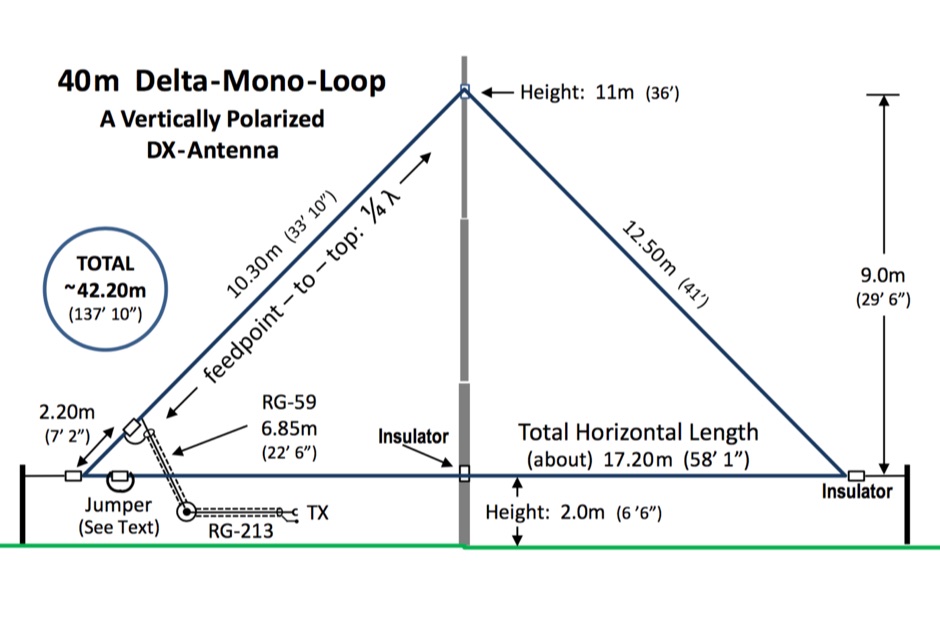 A delta loop antenna project for the 40 meters band, include dimensions 80 meters band, with construction details, schematic and tuning instructions
 -
 MQ-1 four band HF beams 20,15,10,6 meters MQ-2 six band HF beams 20,17,15,12,10,6 meters, beam antennas and Hybrid Quad antennas
 -
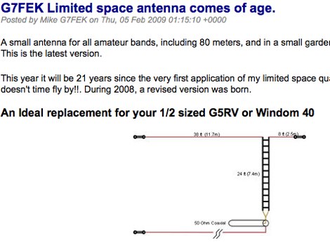 A small antenna for all amateur bands, including 80 meters, and in a small garden without the compromise. An ideal replacement for those half size antennas such as the 1/2 size G5RV and Windom 40
 -
 End-Fed Half-Wave Antennas (EFHWAs) are analyzed for their utility in portable QRP operations, emphasizing their simplicity, efficiency, and predictable radiation patterns compared to other portable antenna types. The discussion contrasts EFHWAs with vertical antennas, random length wires, and center-fed dipoles, highlighting the common pitfalls of each, such as ground system dependency for verticals and feedline issues for dipoles. The article details the electrical half-wavelength calculation using the formula L (Ft) = 468/F(MHz) and explains how EFHWAs can be resonant on harmonic frequencies, enabling multiband operation. Various deployment configurations are presented, including the inverted L, inverted Vee, sloping wire, and vertical setups, each with specific advantages for radiation angle and polarization. For instance, a vertical EFHWA offers a low angle of radiation suitable for DX contacts without requiring an extensive ground system. The resource also addresses the counterpoise requirements, suggesting a quarter-wavelength wire or connection to a metallic structure for decoupling. A schematic diagram for a simple parallel-tuned circuit tuner, based on the _Rainbow Bridge/Tuner_ design, is provided, detailing component values for 30 and 40 meters, including a 6 microhenry toroidal inductor and a 20-100 picofarad mica compression capacitor. The tuner's adjustment process for SWR matching is also outlined.
 -
 Presents the design and construction of an automatically tuned 7-30 MHz mobile HF vertical antenna, originally published in _QEX / Communication Quarterly_ in 2003. The resource details a base-loaded vertical antenna system that mounts on a vehicle's roof, incorporating a variable inductor as its loading coil. A three-legged chariot, driven by a modified model airplane servo, travels inside the coil to adjust inductance. The control unit, featuring a _Basic Stamp microcontroller_ and SWR sensor, emulates a Kenwood AT-50 tuner for seamless integration with a _Kenwood TS-50_ transceiver, allowing automatic tuning across all ham bands from 40 to 10 meters. The project emphasizes practical application, providing a solution to the narrow-banded nature of mobile HF antennas and the inconvenience of manual band changes. It achieves a maximum SWR of 1.3:1 across its operating range. The mechanical design is thoroughly documented with detailed drawings, including a full-resolution GIF and AutoCAD R14 DWG files, illustrating components like the stainless steel whip, PVC coil tube, and the servo-driven chariot mechanism. Construction requires a lathe, but the author notes it can be accomplished with a hobby lathe, making it accessible to those with moderate mechanical skills.
 -
 The Buddipole website showcases a range of portable amateur radio antenna systems, including the **Buddipole**, Mini-Buddipole, Buddistick PRO, and BuddiHEX, designed for rapid deployment and multi-band operation from 40 meters to 2 meters. Each product page details specifications, operational modes (dipole or vertical), and compatible accessories like tripods, masts, and baluns. The site also features portable DC power management systems such as the PowerMini 2 and PowerPlus, which include integrated battery chargers and solar controllers, catering to off-grid or field day setups. Instructional videos demonstrate antenna assembly, tuning, and deployment techniques for various configurations, including the VersaTee vertical and Mini-Buddipole. Customer testimonials and DXpedition highlights, such as operations from Montserrat (VP2M) and Dominica (J38), provide real-world examples of the equipment's performance in challenging environments. The company, established in 2001, emphasizes modularity, versatility, and efficiency in its product line, all manufactured in the USA. Shipping information, a 30-day return policy with no restocking fee, and contact details for their Heber City, Utah facility are clearly presented. The site serves as a direct sales portal, offering a comprehensive catalog of antennas, power solutions, and components for portable amateur radio enthusiasts.
 -
 This article describe a small single wire antenna running on the side of the building allow operations on 80 meters band
 -
 This technical note explores the application of **Moxon rectangle** antennas for WARC bands, specifically 17 and 12 meters, as compact directional alternatives to standard Yagis. It details three design approaches: a dual-band Moxon using open-sleeve coupling, a Moxon-Yagi combination, and a simplified 1.5 Moxon rectangle. The document provides specific dimensions in feet for aluminum tubing elements (0.75" and 0.5" diameter) for each configuration, along with projected free-space gain, front-to-back ratio, and feedpoint impedance (R+/-jX Ohms) across the respective band segments. Performance tables illustrate gain (dBi), front-to-back ratio (dB), and 50-Ohm VSWR for each design. The dual-band Moxon, despite its compact 7-foot boom, is not recommended due to extreme sensitivity to construction variations, leading to rapidly changing performance characteristics. The Moxon-Yagi combination, featuring a 17-meter Moxon and a 12-meter director-driver Yagi, is presented as a more practical and adjustable solution, offering stable performance with a 10-foot boom. NEC model descriptions are included for simulation in programs like EZNEC, NEC-Win Plus, AO, or NEC4WIN.
 -
 An experimental antenna, similar to the _TAK spiral antenna_, was evaluated for SWR response over the 7.0 to 7.3 MHz frequency range. The analysis presents specific results: beam length significantly affects SWR, with increased distance between spirals raising the resonant frequency; the combined length of antenna and hookup wire lowers the resonant frequency as it increases; and spiral diameter impacts bandwidth, with larger diameters yielding greater bandwidth. The design addresses the fixed beam length limitation of the commercial TAK antenna by introducing an adjustable version constructed primarily from PVC electrical conduit and water pipe, using 14-gauge aluminum wire. The resource includes a detailed mechanical design, construction steps, and a parts list. It also features a spiral antenna spreadsheet model for calculating design parameters like start point, pitch, safe edge, spoke length, and arm length, which aids in determining wire length and kerf cutting tables. Model verification involved constructing an antenna to specific parameters, with SWR tests conducted using an _MFJ Model 269_ antenna analyzer at 13 feet above ground with 60 feet of RG8 mini coax. Measurements showed that adjusting beam length from 27 to 37 inches shifted the resonant frequency by approximately 0.18 MHz. Further data compares 32-inch versus 48-inch diameter spirals, demonstrating increased bandwidth for the larger diameter. The model accurately predicted revolutions for given antenna lengths, pitch, and starting distances. The final design achieved a resonant frequency of 7.17 MHz, favoring the voice portion of the 40-meter band after adjustments.
 -
 The document details the optimization and construction of the _Maria Maluca_ antenna, a compact 6-band (20m-6m) directional beam. It presents a comparative analysis of shortwave antenna principles, highlighting the efficiency gains achieved by using an open feeder line and tuner as a resonant unit, contrasting this with the losses associated with traps or capacitive loads in multiband antennas. The resource specifically revisits an older South American 2-element design for 10, 15, and 20 meters, applying modern NEC-based software to develop a six-band version. Performance data is meticulously tabulated, showing impedance, free space gain, gain at 12m height, elevation angle, and front-to-back (F/B) ratio for each band from 20m through 6m. For instance, on 15m, the antenna achieves 5.1 dBd free space gain and 13.72 dB F/B ratio. The construction section provides practical guidance on element assembly using aluminum pipes and hose clamps, detailing the use of a heavy-duty glass fiber reinforced polyamide rod for electrical separation and bending strength. It also specifies the use of 450-ohm _Wireman_ line CQ 552 for the transmission line. The document includes diagrams for rod fixing, an air-wound balun, and a vertical elevation diagram for the 15m band, illustrating its DX qualification. It also discusses the antenna's suitability for portable and expedition operations, noting its compact transport dimensions (max 1.50m length, 12 lb weight) and quick assembly time (under 15 minutes). The author, Dipl.Ing. Helmut Oeller, DC6NY, is identified as a source for material kits.
 -
 For radio amateurs seeking compact, directional antenna solutions, the Moxon Rectangle offers an attractive alternative to traditional two-element Yagis. This resource compiles several articles by L. B. Cebik, W4RNL, exploring the **Moxon Rectangle** design, which provides gain comparable to a full-size two-element array but with a significantly improved **front-to-back ratio** and a direct 50-Ohm feedpoint match. The collection covers both wire arrays, particularly for lower HF bands, and rotatable aluminum beam constructions, addressing various aspects of this popular antenna configuration. The articles delve into specific band applications, including designs for 10 meters, 40 meters, and 2 meters, alongside discussions on multi-banding techniques and pattern characteristics. Comparisons are drawn between the Moxon and other antenna types, such as VK2ABQ Squares, highlighting the Moxon's advantages in terms of size and performance. Practical construction notes are provided for both wire and aluminum versions, offering insights into building these antennas for different operating environments.
 -
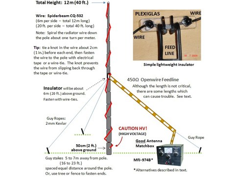 A 40 ft vertical dipole antenna that can cover HF Bands from 80 to 10 meters winding a dipole in a 12m HD telescoping fiberglass pole
 -
 The ARRL page, titled "The HF Mobile Antenna," serves as a curated index to various _QST_ articles focusing on constructing mobile HF antennas. It presents several projects for the mechanically inclined amateur, suggesting that homebrewed antennas can achieve efficiency comparable to commercial versions. For instance, one entry details a **five-band** antenna for RVs, utilizing a fold-over Hustler 4BTV, while another describes a "Bug Catcher" design for 80 through 10 meters. Further projects include a budget-friendly $20 HF mobile antenna made from PVC and wire, covering 20 through 6 meters, and the "Alpha Special," a multiband horizontal antenna originally for 1960s station wagons, now suggested for mini-vans. The resource also addresses antenna mounting solutions specifically for travel trailers and campers, providing practical insights for those operating from recreational vehicles. Rounding out the collection are the "Connecticut Longhorn," a 75-meter horizontal whip with remote tuning, and its redesign, the "Connecticut Shorthorn," adapted for smaller vehicles post-1970s. This compilation offers a historical perspective on mobile antenna innovation and practical construction guides for various HF bands and vehicle types.
 -
 VE7CA experiments on 160 meters band antennas, looking for better performances on reception.
 -
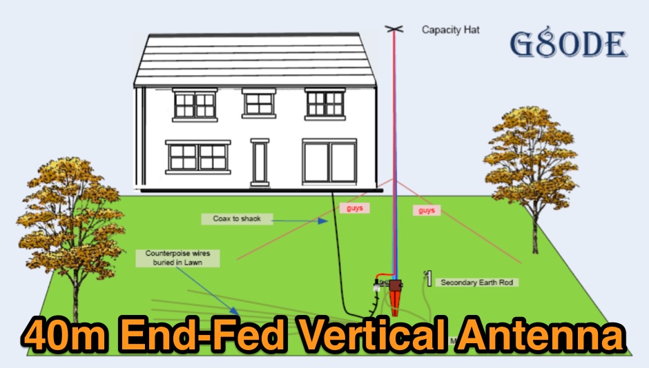 A quarter wave vertical end-fed antenna for the 40 meters band. As all vertical antennas, also this aerial requires a good earthing system. In this project the ground is composed by twelve 4, wires buried in the lawn by using a spade to create a slit to drop the wire into.
 -
 Illustrates the construction of a compact _Moxon_ beam antenna specifically tailored for the 40-meter band (7 MHz). The resource details a homebrew project by W7XA, emphasizing its design for limited space while maintaining good bandwidth and directivity characteristics. It highlights the practical application of the _Moxon_ rectangle model to achieve performance on a lower HF band. The primary content is a downloadable PDF document titled "40-Meter-Mini-MOXON-Beam-Antenna.pdf," which provides comprehensive illustrations and technical specifications for replicating the antenna. This includes dimensions, materials, and assembly instructions, making it a practical guide for radio amateurs interested in directional antennas for HF. The project demonstrates how a relatively small footprint can yield a directional antenna suitable for DXing or contesting on 40 meters, a band typically requiring much larger arrays for similar gain and front-to-back ratios. The documentation supports hands-on construction.
 -
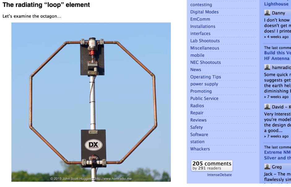 A well documented article on a small magnetic loop antenna for the 40 meters band
 -
 Demonstrates the design and construction of a 9-element Yagi antenna for the **70 cm band** (432 MHz), based on the DK7ZB concept. The resource details EZNEC+ calculations for a single antenna, providing gain, sidelobe suppression, and front-to-back ratio figures. It also presents a comprehensive analysis of stacking two such antennas, including optimal stacking distance (1000 mm) and the resulting performance enhancements for the stacked array, such as an increased gain of 17.03 dBi. The article includes detailed drawings, wire file dimensions in millimeters, and azimuth/elevation plots for both single and stacked configurations. Practical construction steps are documented with original photographs, illustrating element mounting, the **28 Ohm matching system** using two quarter-wave 75 Ohm transmission lines, and the critical N-connector wiring. It also covers the iterative process of fine-tuning the driven element length to achieve a return loss of 20 dB, validating the EZNEC+ simulation results with actual measurements.
 -
 One specific challenge in the KazShack, operating Single Operator Two Radios (SO2R), involved sharing a K9AY receive antenna between two transceivers without direct RF connection or manual feedline swapping. The solution, detailed in this project, adapts the **W3LPL RX bandpass filter** design to split 160m and 80m signals, feeding them to separate radio inputs while maintaining isolation. This approach also addresses the issue of strong broadcast band interference from a nearby 50KW WPTF transmitter on 680kc. The construction utilizes T-50-3 toroids and NP0 ceramic capacitors, built in a "dead bug" style on copper clad board. Each band's filter coils are identical and resonated to the desired frequency using an MFJ-259 antenna analyzer. A single DPDT relay, controlled by a remote toggle switch mounted on an aluminum panel, facilitates quick band switching between radios, simplifying low-band operations. While some signal loss is noted, the expected lower noise levels from the receive antenna are anticipated to compensate, potentially reducing the need for constant volume adjustments during toggling between transmit and receive antennas.
 -
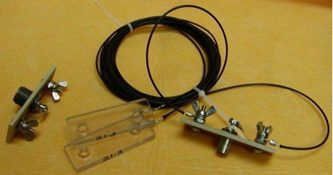 W4ZT used this antenna for Field Day and other portable applications. He built them for all bands between 160 meters and 6 meters. You can make them easily using whatever wire you have available and make the insulators from scrap plastic
 -
-
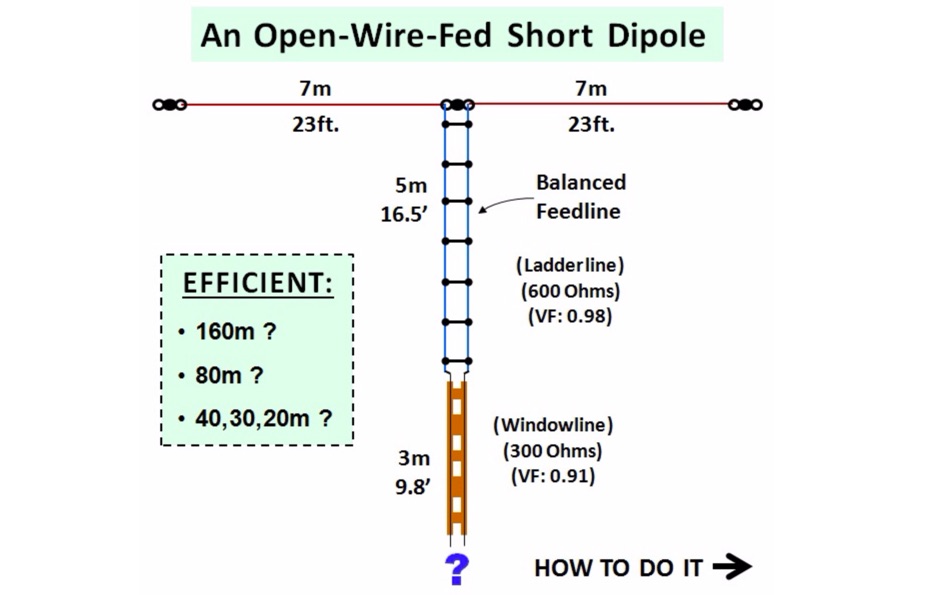 A shortened 160 meters band antenna for hams who do not have 260 ft of space, based on a open-wire-fed short dipoole
 -
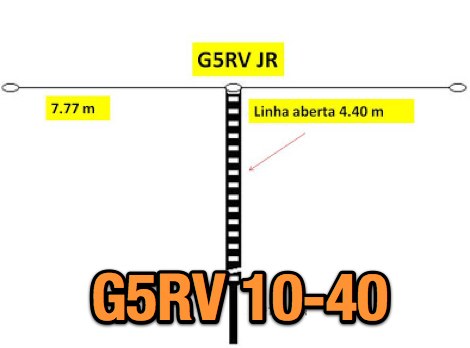
 The G5RV multiband HF antenna, designed by Louis Varney (G5RV) in 1946, is a popular compromise antenna offering good overall performance on most HF bands when paired with an external antenna tuner. The basic full-size G5RV measures 102 feet across the top for 80 through 10 meter operation and is fed at the center via a 34-foot low-loss feed-stub. This interaction between the radiating section and the feed-stub facilitates matching across 80-10 meters with a standard tuner, often eliminating the need for ladder line directly to the shack. The antenna's design center frequency is 14.150 MHz, configured as a 3/2-wave dipole on 20 meters, with its 102-foot length derived from long-wire antenna formulas. Construction details emphasize the matching section, which can be open wire, ladder line (window-type), or TV twin lead. Each type has a specific velocity factor (VF) affecting its physical length for an electrical half-wave on 14 MHz; for instance, open wire requires 33.7 feet (VF 0.97), ladder line 31.3 feet (VF 0.90), and TV twin lead 28.5 feet (VF 0.82). The article provides formulas for calculating these lengths and discusses the antenna's behavior on individual bands, from 3.5 MHz where it acts as a shortened dipole, to 28 MHz where it functions as two three-half-wave long-wire antennas fed in-phase. Practical construction notes include recommendations for vertical descent of the matching section, sealing the coax junction, providing strain relief, and winding a coaxial choke coil to mitigate common mode current. The resource also presents dimensions for double-size (204 ft) and half-size (51 ft) G5RV versions, along with their corresponding matching section lengths for various line types, making it a versatile reference for hams considering this classic wire antenna.
 -
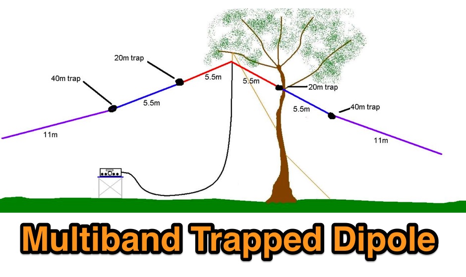 An homemade portable trapped dipole antenna for 40 and 80 meters band with an optional extension for the 20 meters.
 -
 Demonstrates the construction of a _3MA triband mobile antenna_ designed by IZ7DJR, emphasizing a full-size quarter-wave whip for 10 meters. The design incorporates a rapid tilt-down mechanism to facilitate quick changes of loading coils for operation on 15 and 20 meters. This approach aims to minimize losses and enhance efficiency compared to conventional base-loaded mobile antennas. The resource provides specific coil winding data: 22 turns for 15 meters and **37 turns** for 20 meters, both using 1mm wire over an 80mm coil length. The 10-meter band operates without a loading coil, leveraging its full-size design. The author's design prioritizes ease of band switching and improved performance for mobile HF operations, offering a practical alternative to more lossy commercial options.
 -
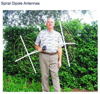 Experiments with spiral dipole antennas. Includes two spiral antenna designs for 20 and 40 meters band by KN9B