Search results
Query: dBm
Links: 33 | Categories: 0
-
 The website https://www.qsl.net/dl5dbm showcases homebrew projects related to KW, 2-meter, 6-meter, antennas, amplifiers, preamps, power supplies, and more. It provides information and resources for radio amateurs interested in DIY projects and experimentation.
-
-
 A whip antenna for VHF and UHF handhelds or mobile radios
-
-
 This transverter was built in 1994, a discription in three parts (german language) for DOWNLOAD as PDF-files. Circuit, printed-boards and layouts in the files
-
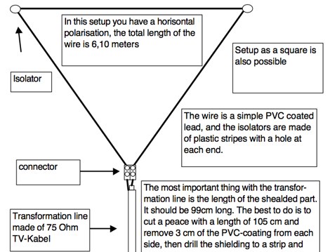
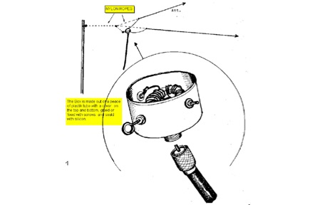 A complete documentation with pictures and design of a deltaloop antenna and 1:2.5 balun
-
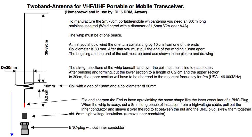 A project by DL5DBM for a VHF UHF antenna suitable for handheld transceivers
-
 Over 45 years of amateur radio experience inform the homebrew projects detailed on this personal website, with a particular focus on microwave frequencies. The site showcases a 24 GHz transverter and a more recent 47 GHz transverter, demonstrating practical construction techniques for extreme high-frequency operation. These projects often involve custom circuit design and careful component selection to achieve stable performance at millimeter-wave bands. Key projects include a _harmonic converter_ for frequency measurement and a tracking spectrum analyzer, essential tools for microwave experimenters. The site also documents a CW sidetone generator and a TX/RX sequencer, illustrating fundamental building blocks for radio equipment. Details on a digital frequency meter and an S-meter/dBm meter provide insights into test equipment construction. Specific achievements, such as a **24 GHz** tropo QSO with DK3SE in 2021, highlight the operational success of these homebrewed systems. The content reflects a long-standing dedication to self-sufficiency in amateur radio, providing practical examples for those interested in building their own gear.
-
 Pictures and circuit diagramm to build this power amplifier for 2 meters
-
 Homebrew with CF300 DGMF with about .24 dBD gain
-
 Homebrew a 2m/70cm portable or mobile whip antenna for your HT or mobile radio
-
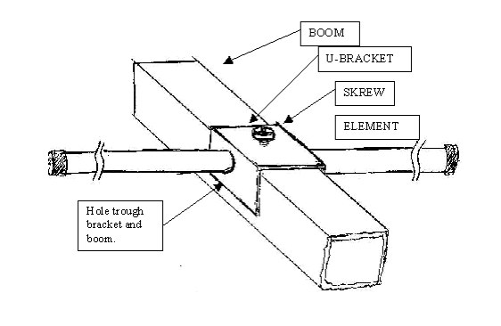 Here is an easy method to mount elements to a boom, this can be realized at home, without the need of special tools
-
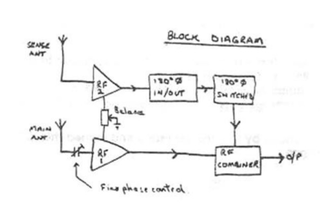 The circuit described below will substantially reduce or completely eliminate interference from almost any local source whilst leaving the wanted signal relatively unaffected, even though it may be on the same frequencey by TREVOR, G3ZYY
-
 Balun case construction, tipically to host toroid cores. Size of case depends on power to handle. By DL5DBM
-
 The Receiver Test Data resource is a detailed review database focusing on the performance metrics of various radio receivers. The methodology involves rigorous lab measurements, often adhering to standards such as the ARRL RMDR (Reciprocal Mixing Dynamic Range) and BDR (Blocking Dynamic Range). Specific test equipment and protocols are utilized to assess parameters like noise floor (dBm), AGC threshold (uV), and LO noise (dBc/Hz). For example, the _Icom IC-7300_ is evaluated with a noise floor of **-133 dBm** and an LO noise of **-141 dBc/Hz**, providing insights into its performance under different operational conditions. The resource includes a wide range of models, from the _Elecraft K3S_ to the _Yaesu FTdx-101D_, each tested for dynamic range, sensitivity, and selectivity. The data is sorted by key metrics such as third-order dynamic range and phase noise limitations, with RMDR values calculated by subtracting 27 dB from LO noise figures. This structured approach allows users to compare different receivers' capabilities, focusing on technical specifications and performance outcomes in various scenarios. DXZone Focus: Review Database | Lab Measurements | -133 dBm | ARRL RMDR
-
 The decibel (dB) is a logarithmic unit used to measure sound level, widely applied in electronics, signals, and communication to describe power, sound pressure, voltage, or intensity ratios. For instance, a 3 dB increase signifies a doubling of power, while a 10 dB increase represents a tenfold power multiplication. Sound pressure level is calculated as 20 log (p2/p1) dB, reflecting the square relationship between power and pressure. Standard reference levels, such as 20 micropascals for sound pressure in air, establish absolute dB values, where 0 dB corresponds to the reference level, not an absence of sound. Human hearing sensitivity varies with frequency, necessitating A and C weighting filters (dBA, dBC) in sound meters to approximate the ear's response. The phon unit relates to dB via psychophysically measured frequency response, with 1 kHz readings being identical. The sone unit quantifies perceived loudness, where 1 sone equals 40 phons, and a 10 dB increase above 40 phons roughly doubles perceived loudness. In radio, dBi measures antenna gain relative to an isotropic radiator, crucial for anisotropic radiation patterns.
-
 Details the construction of an **HF converter** designed by M1GEO, George Smart, specifically to extend the frequency range of the FunCube Dongle Pro (FCD) for amateur radio reception. The FCD natively covers 64 to 1,700 MHz, but this project enables reception from 0 Hz to 64 MHz by up-converting signals to the FCD's operational range. It employs a **double-balanced mixer** with a 100 MHz local oscillator (LO) to translate incoming HF signals; for instance, a 1 MHz signal appears at 101 MHz within the FCD's passband. The design incorporates a 7th-order Chebyshev low-pass filter with a 62 MHz cutoff frequency at the input to mitigate image frequencies, ensuring cleaner spectral presentation. George provides the schematic, PCB masks, and Gerber files for replication, noting that Far Circuits also offers PCBs. The resource includes test results for the low-pass filter and measurements of LO leakage, identifying -36.8 dBm at 100 MHz as a potential sensitivity concern. M1GEO discusses potential improvements, such as adjusting the mixer's LO drive, adding a balance pot, or incorporating a post-mixer high-pass filter to reduce LO breakthrough. Audio recordings from 40m and 17m demonstrate the converter's performance with WRplus SDR software.
-
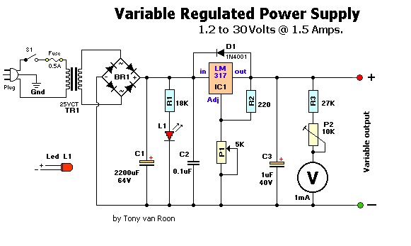 1.2 to 30 Volts 1.5 Amps Power Supply
-
 Understanding power measurements in RF systems is crucial for amateur radio operators, particularly when evaluating antenna performance or transmitter output. This online resource provides a _dBm calculator_ and a comprehensive reference table specifically tailored for 50 Ohm impedance environments. The calculator allows users to convert between dBm, milliwatts (mW), and volts (V), facilitating quick power level assessments. It clarifies that dBm represents a logarithmic ratio with a reference power of **1.000 milliwatt**, equating to 0 dBm. The accompanying reference table extends this utility by presenting a range of pre-calculated values, which can be particularly useful for field operations or rapid design checks without needing to perform manual calculations. The resource distinctly focuses on the practical application of dBm in amateur radio contexts.
-
 A synthesized 2.3 GHz Amateur Television (ATV) transmitter design, conceived by Ian G6TVJ, is presented, targeting broadcast-quality video performance on the 13cm band and extending up to 2.6 GHz. The core of the design utilizes a commercial Z-comm Voltage Controlled Oscillator (VCO) that tunes from 2.2-2.7 GHz, providing a +10 dBm output and simplifying RF alignment. This VCO's stability, originally intended for narrowband applications, readily accepts high-frequency video modulation, contributing to the transmitter's robust performance. The exciter stage, incorporating a Mini Circuits VNA 25 MMIC amplifier, boosts the signal to +16dBm, while a Plessey SP4982 prescaler divides the output frequency for the synthesizer. The synthesizer employs a Motorola MC145151 CMOS parallel IC, favored over the common Plessey SP5060 for its superior video modulation characteristics and ease of programming without microprocessors. This choice addresses issues like LF tilt and distorted field syncs often seen with SP5060 designs, particularly when operating through repeaters or over long distances. The MC145151 divides the signal further, enabling precise frequency stepping, with programming handled by EPROMs for channel selection and LED display. The loop filter network, critical for video integrity, was developed through experimentation to prevent the PLL from reacting to video modulation, ensuring a clean transmitted picture. The transmitter incorporates a Down East Microwave commercial power amplifier module, delivering approximately 1.6W output, driven by the exciter through a 3dB attenuator. Construction involves surface-mount SHF components on micro-strip lines etched onto double-sided fiberglass board, housed within a tinplate box. The design boasts no AC coupling in the video path, preserving low-frequency response, a common failing in other ATV transmitters. Performance tests with a 50Hz square wave revealed no LF distortion, and a calibrated "Pulse & Bar" signal showed a near 100% HF response, demonstrating its capability for high-quality ATV transmissions.
-
 Multiband Trap Dipole, portable short antennas, accessories and kits by DG1DBM
-
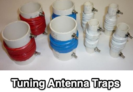 The problem with making your own trapped HF antennas is usually getting the coaxial traps tuned to frequency. This article explains a method using a RF signal generator at +10dBm output into the coaxial trap.
-
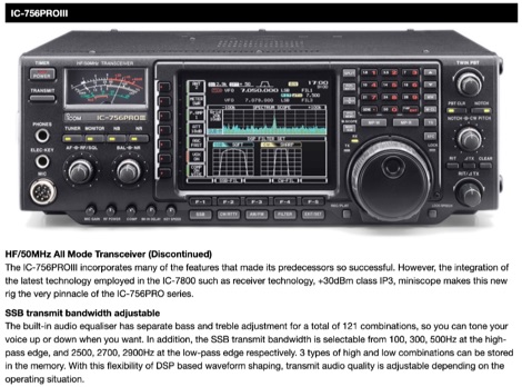 A page dedicated tho the IC-756PROIII transceiver. This radio, discontinued, incorporates many of the features that made its predecessors so successful. However, the integration of the latest technology employed in the IC-7800 such as receiver technology, +30dBm class IP3, miniscope makes this new rig the very pinnacle of the IC-756PRO series.
-
 dBm to watts conversion calculator and explaination on how to convert dBm to watts, including dBm to watts conversion table
-
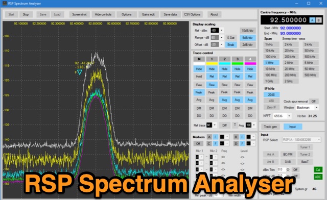 The analyser has been written to support the full range of SDRplay SDR radios including the new RSP1B. The analyser is capable of resolution bandwidths of less than 1Hz with sensitivity better than -145dBm. In addition to being able to run five separate traces, the analyser offers the ability to capture screen shots, export data in a range of formats and includes a versatile marker system. The analyser includes a comprehensive user manual and offers a very useful addition to any workbench.
-
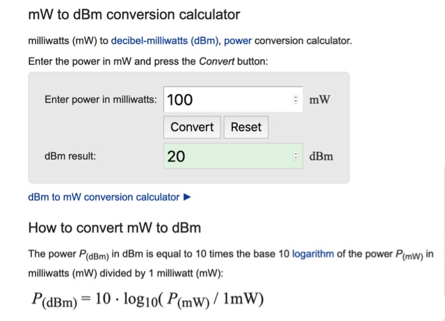 Online calculator that will convert power entered in milliwatts to dBm. Includes a quick mW to dBm conversion table
-
 This project details the development of a modular direct conversion (DC) receiver designed for experimental flexibility in amateur radio and HF signal listening. The mainframe integrates a diplexer, DBM, and AF amplifier, supporting interchangeable local oscillator and antenna filtering setups. A tunable passive HF preselector complements QRP Labs bandpass filters for enhanced signal reception. Utilizing a NanoVNA for precise tuning, the receiver achieves improved signal-to-noise ratios across amateur and non-amateur bands, making it a versatile platform for further RF experimentation.
-
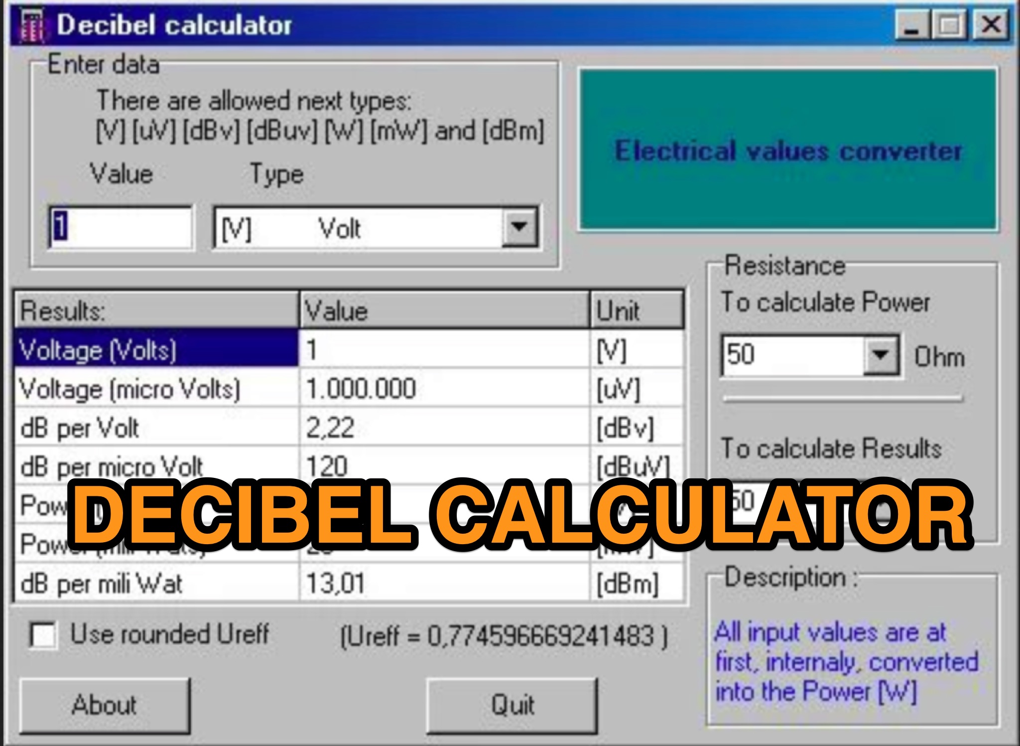 Learn how to easily convert between different units like dBu, dBm, W, mW, V, and uV with the dBCalc application. This small windows program allows ham radio operators to quickly check conversions using input and output resistance. It's a useful tool for anyone dealing with electronic measurements and calculations. Best of all, dBCalc is free to use, making it a convenient solution for amateur radio enthusiasts. This tool simplifies complex conversions and helps hams optimize their equipment setup.
-
 This article provides a comprehensive introduction to the decibel (dB), its logarithmic nature, and its applications in power, voltage, and antenna gain calculations. It explains how dB simplifies comparisons in electronics, telecommunications, and audio perception. The author clarifies key mathematical concepts, including power ratios, voltage doubling, and absolute levels like dBm and dBV. The discussion on S-units and antenna system gain is particularly relevant for radio amateurs. Overall, this is an informative and well-structured guide to understanding and applying decibels in technical fields.
-
 The page features a spreadsheet that calculates power in watt and dBm based on voltage and impedance, power in dBm with a given power and impedance, voltage in millivolts with a given power and impedance, and more. It also converts between millivolt, microvolt, volt, watt, and milliwatt. Useful for hams looking to accurately calculate power and voltage values for radio equipment. Last updated in December 2014.
-
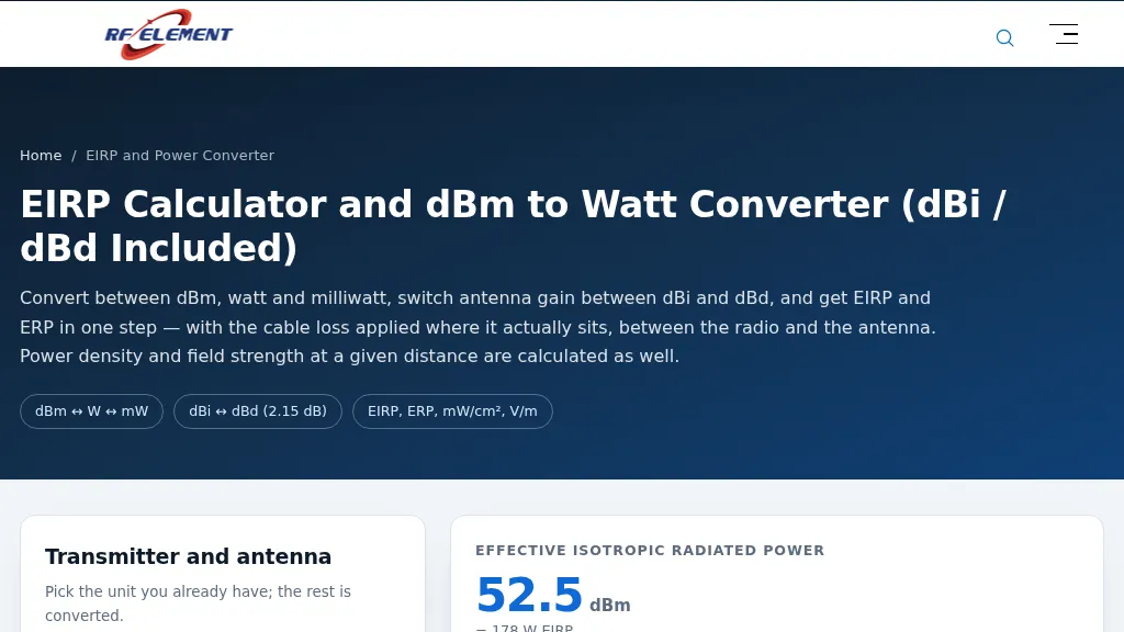 Demonstrates an online calculator for determining _Effective Isotropic Radiated Power_ (EIRP) and Effective Radiated Power (ERP) in radio and antenna systems. Users input transmit power in dBm, antenna gain in dBi or dBd, and feeder loss in dB, with the tool converting between dBm, watts, and milliwatts. It also calculates power density in µW/cm² and equivalent field strength in V/m at a specified distance, applying feeder loss before the EIRP calculation. The resource provides a quick reference table for common dBm to watt conversions, such as **30 dBm** equaling 1 W, and clarifies that 3 dB of loss halves radiated power. The calculator distinguishes between EIRP and ERP, noting that ERP is always **2.15 dB** lower than EIRP due to its half-wave dipole reference. It explains the importance of understanding the difference between dBi and dBd, as a 30 dBi antenna is not the same as a 30 dBd antenna, with the latter being 2.15 dB stronger. The page includes a table of typical EIRP limits for various bands and regions, such as 36 dBm for 2.4 GHz ISM US, FCC Part 15.247, and offers insights into regulatory considerations and the limitations of power density figures for safety compliance.
-
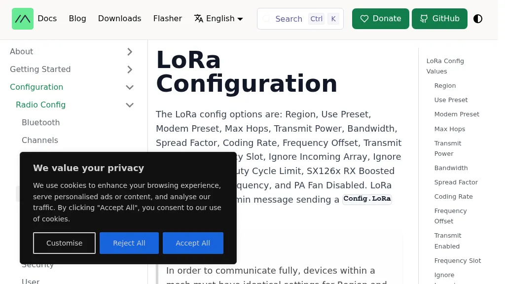 The Meshtastic documentation outlines critical LoRa configuration parameters for node operation, emphasizing regulatory compliance. It details settings such as Region, Modem Preset, Max Hops, Transmit Power, Bandwidth, Spread Factor, Coding Rate, and Frequency Offset. A comprehensive table provides region codes, frequency ranges (e.g., US **902.0 - 928.0 MHz**), duty cycles, and power limits (e.g., EU_433 **12 dBm**) for numerous countries, including the US, EU, China, and Japan, alongside a 2.4 GHz band option. It explicitly states that devices within a mesh must share identical _Region_ and _Modem Preset_ settings for full communication. Modem Presets, like _LONG_FAST_ (the default), optimize for either speed or range, directly impacting network congestion and message delivery delay. For instance, SHORT_TURBO offers the fastest speed and shortest range, while VERY_LONG_SLOW provides the longest range but is less reliable for mesh formation. The document also highlights specific duty cycle limitations, such as the 10% hourly limit for EU_433 and EU_868 regions, and provides command-line interface (CLI) examples for configuring these parameters.
-
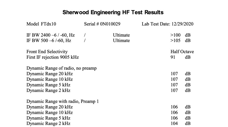 The Yaesu FTdx10 HF transceiver underwent comprehensive laboratory testing by Sherwood Engineering, with results documented on December 29, 2020. Key receiver performance metrics include IF bandwidth measurements at -6 dB and -60 dB for 2400 Hz and 500 Hz filters, showing ultimate rejection exceeding 100 dB and 105 dB respectively. Front-end selectivity and first IF rejection at 9005 kHz were measured at 91 dB. Receiver dynamic range, both with and without preamps, was consistently 107 dB at 20 kHz, 10 kHz, 5 kHz, and 2 kHz spacings without preamplification, and 106 dB with Preamp 1 at 20 kHz. Blocking performance reached 141 dB at 100 kHz offset with a 1uV signal. Phase noise was normalized across offsets from 2.5 kHz to 500 kHz, with a value of -145 dBc/Hz at 2.5 kHz and -155 dBc/Hz at 500 kHz. Reciprocal Mixing Dynamic Range (RMDR) peaked at 128 dB at 500 kHz spacing. Noise floor measurements for SSB and 500 Hz bandwidths at 14 MHz and 50.125 MHz showed -133 dBm with Preamp 2 at 14 MHz SSB. Sensitivity figures and S-meter accuracy were also documented, with one S unit equating to 3 dB from S3 to S9. Transmitter composite noise was measured at 100 watts and 30 watts, with values like -123 dBc/Hz at 2 kHz offset for 100 watts. Operational observations from the January 2021 CQWW 160m CW contest highlighted ergonomic issues, such as VFO knob placement and small buttons. A significant firmware limitation noted was the band scope and waterfall data being erased upon transmission, which severely reduces its utility for search and pounce operations.