Search results
Query: led counter
Links: 36 | Categories: 0
-
 A 9 dB gain 70cm collinear antenna construction is detailed, utilizing eight half-wavelength sections of _RG58/U_ coaxial cable. The design incorporates specific calculations for velocity factor (0.66 for RG58/U) to determine precise element lengths, such as 223mm for a half-wavelength at 444 MHz. A quarter-wave radiating element of #16 solid wire, 169mm long, is added to the top, and a 160mm aluminum tube acts as a quarter-wave counterpoise at the feed point. RF choke baluns, constructed from three _FT50-43_ toroids, are positioned a half-wavelength from the feed point to mitigate common mode current. Assembly involves soldering the coax sections in series, followed by SWR testing during construction and final mounting within a ¾-inch PVC pipe. The article suggests using four half-wave elements for a shorter antenna, noting a potential slight increase in SWR, which can be mitigated with quarter-wave ground radials. The design principles and formulas are scalable for other VHF/UHF bands like 6m, 2m, or 1¼m, providing a versatile homebrew solution for enhanced gain.
 -
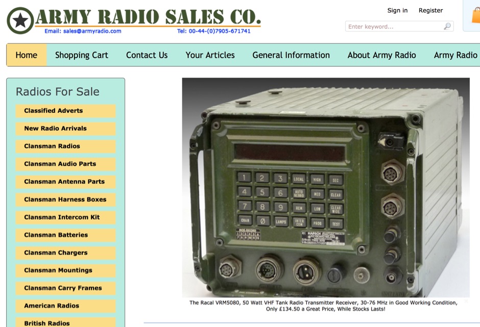 The Racal VRM-5080 VHF FM Radio Transceiver, designed for military vehicle installation, operates across the 30 to 76 MHz frequency band with 50 Watts of output power. This unit, along with other featured items like the DOM-410 Geiger Counter and the RT-524/VRC VHF Vehicle Radio Station, represents the core offerings of Army Radio Sales Co. The site provides detailed technical specifications for each product, including frequency ranges, power output, channel spacing, and operational voltage, catering to collectors and restorers of vintage military communications gear. Beyond product sales, the website serves as a repository for historical information, offering access to military radio manuals, articles, and thousands of pictures. Resources such as the SCR-694 / BC-1306 Radio Signal Corps Training Film and TM 11-2715 Installation of Radio Equipment in 1944 Jeeps are available. The platform also hosts a free classifieds section for users to advertise their military radio needs and offers insights into related military vehicle projects. Additional content includes information on the STR37E VHF Aircraft Radio Transceiver, operating from 116.00 MHz to 135.95 MHz, and the R-442/VRC VHF Vehicle Radio Receiver, covering 30-75.95 MHz. The site also features articles on topics like the Ukrainian Expedition and data plates for military Jeeps, broadening its appeal to military history enthusiasts.
 -
 A **mobile HF multiband antenna** project details the construction of a center and top-loaded design, optimized for 10 through 80 meters. This antenna incorporates a capacity hat positioned high on the whip for enhanced efficiency, differing from commercial bugcatcher designs. The coil construction prioritizes high Q and minimal loss through an air core, open spacing, and heavy gauge wire, contributing to its lightweight nature and suitability for portable operation with a proper counterpoise. Band switching is achieved by manually moving a jumper plug to various tap points on the coil, allowing for operation across multiple bands, with 17m being resonant when the coil is bypassed. The design, a result of nine months of experimentation by N1LO, includes detailed instructions for modifying a Hamstick antenna base, creating a jumper wire, and assembling the capacity hat using stainless steel wire and silver-bearing solder for robust connections. The loading coil utilizes nylon grommet strips around a PVC pipe for an air-core winding, ensuring high efficiency. Tap sockets are fashioned from silver-plated 5-way binding posts, providing low-resistance RF joints for band selection. Guidance on tap point determination emphasizes using an antenna analyzer like the MFJ 259B or 269 to achieve resonance, especially on 40m and 80m where feedpoint resistance can be low. The document also covers the installation of monofilament stays to maintain antenna uprightness at highway speeds, with specific attachment points for stability.
 -
 Presents a practical approach to constructing a portable, lightweight antenna support structure, ideal for field operations or temporary installations. The design utilizes readily available PVC pipe sections, allowing for a total height of **20 feet** and a transportable weight of **25 lbs**. Detailed material lists specify various PVC pipe diameters and lengths, along with couplers, tees, and elbows, facilitating a modular assembly that can be easily disassembled for transport. Accompanying the tower design, the resource also outlines the construction of a _MicroVert_ antenna, including formulas for radiator length, capacitance, and inductance. It provides guidance on creating a current balun using ferrite beads or a coax coil, and calculating counterpoise length for optimal performance. The antenna section includes a schematic diagram illustrating the connection of the SO-239 connector and counterpoise.
 -
 A 2-meter Turnstile antenna, detailed for amateur satellite communication, offers a straightforward build for those looking to engage with orbiting transponders. The author, WB8ERJ, shares his personal design and construction methods, emphasizing the antenna's simplicity and effectiveness for LEO (Low Earth Orbit) satellite work. This design provides a circularly polarized signal, crucial for mitigating _Faraday rotation_ and signal fading often encountered with linearly polarized antennas when tracking satellites. Construction involves readily available materials like PVC pipe and copper wire, making it an accessible project for many hams. The article includes practical advice on element spacing and feed point considerations, drawing from the author's hands-on experience in the shack and field. It highlights the antenna's utility for receiving signals from various amateur satellites, including the popular AO-91 and AO-92. The Turnstile's inherent omnidirectional pattern in the horizontal plane, combined with its circular polarization, yields consistent signal reception, often resulting in **stronger decodes** and **more reliable contacts** compared to basic dipoles or verticals.
 -
 Mirko Pelcl's extensive radio collection features numerous historical transceivers and receivers, with a significant focus on military communications gear. The collection includes notable examples such as the Wireless Set No. 19, various Cold War-era military radios, and even a rare WWII spy radio utilizing a Loewe 3NF tube. Visitors can explore detailed sections dedicated to sets manufactured before 1945, including those used for military exchange, and a separate category for post-1945 radios, particularly those from the former Yugoslavia. The site also delves into specific modifications, like a digital head conversion for the RU-20, and showcases a frequency counter built with a microcontroller. This personal archive provides a unique glimpse into the evolution of radio technology, from early vacuum tube designs to more modern solid-state military transceivers like the PRC-515. The content reflects Mirko's dedication to preserving and documenting these pieces of radio history.
 -
 The N0KHQ Coax Square antenna, designed for 17 meters and built using RG-58 coaxial cable, presents an intriguing option for hams with limited space. L. B. Cebik, _W4RNL_, meticulously models and analyzes this array, clarifying its classification not as a modified Moxon, but as a distinct member of the "dual-coupled, 2-element, parasitic array" family. The design leverages the velocity factor of RG-58 (approximately 0.66-0.67) to achieve significantly shorter element lengths compared to full-size counterparts, resulting in a perimeter of 42 feet for the N0KHQ array versus 54 feet for a standard Moxon. _NEC_ modeling reveals the coax square's performance characteristics, including a forward gain of 5.6 dBi and a 23.7 dB front-to-back ratio on 18.118 MHz. While slightly less gain than a Moxon (6.0 dBi), its pattern exhibits Yagi-like nulls at 90 degrees, distinguishing it from the Moxon's wider beamwidth. The article also delves into the unique feedpoint considerations, explaining how the split braid and center conductor of the RG-58 driver effectively form a folded dipole, allowing for impedance transformation to achieve a good match for 50-Ohm cable. Despite its shortened elements, which inherently narrow the operating bandwidth, the coax square maintains satisfactory performance across the 17-meter band. The analysis emphasizes that while SWR curves are important, a holistic view of gain and pattern degradation across the band is crucial. This antenna is a viable solution for operators needing a compact, directional array, particularly for narrow bands like 17, 30, or 12 meters, where its high-Q performance is most effective.
 -
 Simulates a **CW** contest environment, presenting operators with realistic scenarios for improving their receiving and sending proficiency under pressure. The software generates varying signal-to-noise ratios, QRM, and QRN, replicating conditions encountered during actual **DX** contests. Users practice copying callsigns, exchange information, and manage pileups, with customizable parameters for speed and difficulty. The program provides immediate feedback on accuracy and speed, allowing for targeted skill development in a controlled setting. It supports various Windows operating systems, from Windows 95 through Windows 10, and can also run on macOS using Wine.
 -
 Demonstrates the construction of a base-loaded quarter-wave vertical whip antenna, suitable for both mobile and portable HF operations. This design utilizes a vehicle body as a ground plane for mobile use or a counterpoise for field deployment. The article details the selection of materials, such as a _glass fibre tubing_ former and 24 s.w.g enamelled copper wire for the loading coil, with specific turn counts suggested for 20m (around **30 turns**) and 40m (around **50-60 turns**). It outlines a practical tuning method using an SWR bridge and even an audible signal approach, emphasizing careful adjustment of coil turn spacing or whip length to achieve optimal SWR. The resource also mentions the use of an antenna analyzer for more precise tuning, contrasting it with the SWR method.
 -
 This resource details the conversion of an 80m elevated vertical antenna to include 160m operation, focusing on a relay-switched design over a trap-based approach. It presents specific feedpoint impedance values, such as **32 ohms** for 80m and **14 ohms** for 160m, and discusses the challenges of SWR drift encountered with the prior trap system during RTTY contesting. The article thoroughly explains the design choices for elevated radials, referencing _N6LF QEX data_ to debunk common myths regarding radial length and height, demonstrating that non-resonant radials can offer superior current uniformity. The construction section provides practical insights into building the vertical, including guying strategies, material selection from scrap pipe, and weatherproofing the relay assembly. It highlights the use of a common mode choke for the relay switching line, measuring approximately 5K ohms on both 160m and 80m, and details the L/C matching network's role in achieving a 50-ohm match at the end of a 300-foot RG-11 run. The author describes a precise VNA-based radial trimming procedure, achieving resonant values within a 3 KHz range. The content emphasizes the practical application of theoretical antenna principles, particularly concerning the interaction between the vertical element, cap hats, and the matching network. It offers a candid assessment of component selection, such as using junkbox parts and acknowledging the need for future upgrades to static drain resistors. The article serves as a comprehensive case study for advanced antenna builders tackling multi-band vertical designs.
 -
 FDLog, a Python-based freeware application, addresses the challenge of synchronized logging for multi-station Field Day operations. It facilitates real-time data sharing across a wireless network, enabling operators to monitor band status and active transmitters at a glance. The software's input system is optimized for minimal keystrokes, streamlining the logging process during intense contest periods. Key features include database synchronization over a wireless network, ensuring all connected computers maintain identical log data. FDLog also incorporates a time synchronization function, designed to keep client programs within a second of a designated master machine, mitigating issues previously encountered with NTP. This internal clock sync can be optionally disabled if not required by the operating setup. Developed initially on Windows 2000, FDLog has demonstrated compatibility with _Linux_ and _macOS_ environments, though some font rendering issues may occur on the latter. The program assists in preparing the ARRL Field Day entry form, simplifying the submission of contest results. User feedback and ARRL rule changes drive ongoing development, with a discussion list available for community support and input.
 -
 Over 130 years after its inception, Morse Code remains a fundamental skill for many amateur radio operators, enabling efficient QRP operations, DXing, and contesting. This resource provides an in-depth look at the **Koch Method** of Morse training, a widely adopted technique that emphasizes high-speed character recognition from the outset. It details how this method can significantly accelerate proficiency, moving beyond traditional, slower learning approaches. The site also delves into the rich history of amateur radio, presenting articles such as "Radio on the Rio," which chronicles local ham activity in Socorro, New Mexico. Another piece, "The Russian Woodpecker," recounts the Cold War-era efforts of hams to counter Soviet over-the-horizon radar interference on the HF bands. Furthermore, the resource explores the fascinating intersection of ham radio and radio astronomy, highlighting the direct lineage between amateur experimentation and the development of modern radio telescopes like the **Very Large Array (VLA)**. It also includes an introduction to the 6-meter band, often called "The Magic Band," detailing its unique propagation characteristics and suitability for no-code licensees seeking long-distance contacts.
 -
 This resource details the construction of a portable antenna tripod designed for supporting small vertical antennas, utilizing readily available electrical metal tubing (EMT) or conduit. It outlines the necessary components, including a custom-fabricated _EARC tripod plate_, standard hardware, and a 10-foot section of 1/2-inch EMT cut into specific lengths for legs and a center support. The instructions cover assembly of the tripod plate, leg construction, and integration with a fiberglass fishing pole like the _Kwik Stix_ or _Shakespeare Wonderpole_ to support a vertical wire HF antenna. The project also describes an adaptation for using the tripod with 3/8x24 threaded mobile antennas such as _Hamsticks_ or _Buddisticks_, where the tripod structure itself contributes to the antenna's counterpoise system. A complete parts list is provided, along with ordering information for the specialized EARC tripod plate, which serves as a fundraiser for the Honolulu Emergency Amateur Radio Club. The document includes photos illustrating the assembled tripod and its use with a fiberglass pole.
 -
 Ten essential tips and truisms for understanding HF antenna: Non-resonant wire dipole antennas fed with open-wire line and an antenna tuner can function effectively as multiband antennas, as detailed in "The Classic Multiband Dipole Antenna" by WB8IMY in March 2004 QST. Coaxial cable, unlike balanced parallel-wire feed lines, can cause RF to travel on the outer shield braid, leading to RF feedback to the station; a 1:1 balun at the dipole center can mitigate this by isolating the unbalanced coaxial feed line. Antenna gain is achieved by shaping and directing RF energy, with beam antennas concentrating power in a specific direction, and wire antennas also exhibiting shaped radiation patterns. An antenna tuner's primary role is to match the transceiver's 50-ohm output to the antenna system's impedance, allowing modern transceivers to deliver full power. Wire antennas do not always require center feeding; end-fed long wires or off-center-fed dipoles (like the Windom) can be used, though they often necessitate an antenna tuner and a counterpoise or radial network. Dipole antennas do not need to be perfectly horizontal; their legs can be bent or inclined, which affects feed point impedance and may require SWR experimentation with coaxial feed. Vertical antennas shorter than a half wavelength require an efficient ground system, typically comprising elevated or buried radial wires, with more radials generally leading to better efficiency. A 1:1 SWR indicates an impedance match but does not guarantee antenna efficiency; an inefficient vertical antenna with a poor ground system can show a low SWR while wasting most RF as heat. Investing in high-quality, low-loss feed line, especially coaxial cable, is crucial for maximizing RF signal transfer and overall antenna system performance.
 -
 Presents a detailed resource for DXers interested in Non-Directional Radiobeacons (NDBs), MF, HF, and VHF propagation beacons, and various other radiobeacon types. The site offers access to downloadable information files, including an Abbreviations List, NDB List Country List, and NDB Publications List, which serve as foundational materials for newcomers to the hobby of beacon monitoring and DXing. It covers specialized topics such as DGPS beacons, GMDSS DSC mode, and NAVTEX mode, with dedicated sections providing in-depth explanations. A Beacon Photo Gallery showcases diverse radiobeacon types from around the globe, offering visual context for different systems encountered in the field. The platform also facilitates participation in unique monthly Coordinated Listening Events (CLEs), providing guidelines and schedules for these activities. The resource outlines various associated Groups.io lists, including the primary NDB List for radiobeacons (NDBs, Propagation Beacons, VOR systems), the DGPS List for DGPS DXing, Time Signals, LORAN, and WeFAX modes, and specialist groups like NavtexDX and DSC List for GMDSS-DSC. It details how to join these communities for further engagement and information exchange.
 -
 Operating a ham station often involves encountering radio frequency interference (RFI), RF feedback, or RF burns, which are frequently misattributed to poor equipment grounding. This resource meticulously dissects these assumptions, asserting that RF grounds on the operating desk often merely mask more significant system flaws. It identifies five primary causes for RF problems, including antenna system design flaws, proximity of the antenna to the operating position, DC power supply ground loops, equipment design defects, and poorly installed connectors or defective cables. The content emphasizes that issues like "hot cabinets" or changes in SWR when connecting a ground indicate substantial RF flowing over wiring or cabinets, a phenomenon known as common-mode current. The article provides detailed explanations of common-mode current generation, particularly from single-wire fed antennas like longwires, random wires, and OCF dipoles, which inherently present high levels of RF in the shack. It also illustrates how vertical antennas, lacking a perfect ground system, can excite feed lines with significant common-mode current. Through simulations, the author demonstrates how a dipole without a proper _balun_ can cause RF problems at the operating desk, showing current patterns and voltage distributions on feed line shields. The discussion extends to the proper application of _RF isolators_ and _ferrite beads_, clarifying their role in modifying common-mode impedance on cable shields and cautioning against their use as a band-aid for fundamental system defects. The resource advocates for correcting the actual source of RF problems, such as antenna system issues or poor connector mounting, rather than relying on internal shack grounding or isolators. It highlights that properly functioning two-conductor feed lines, like coaxial or open-wire lines, should result in minimal RF levels at the operating position, even without a desk RF ground. The author shares personal experience, noting that his stations since the late 1970s have operated without RF grounds at the desks, relying instead on proper antenna system design and feed line integrity.
 -
 The F5GIT blog documents the amateur radio pursuits of Tony, F5GIT, offering insights into his DXpedition experiences and contest operations. It presents detailed accounts of his participation in events like the _CQ WW DX Contest_ and the _IARU HF Championship_, often including specific callsigns worked and operational strategies employed. The resource covers various aspects of station setup, antenna configurations, and radio equipment used for achieving contacts across different bands. Content includes discussions on antenna performance, such as a **2-element Yagi** for 10/15/20 meters, and operational challenges encountered during remote or portable setups. The blog also serves as a personal log, chronicling significant QSOs and providing a historical record of his amateur radio journey. It details specific locations operated from, like _Île de Ré_, and the unique challenges presented by such environments. Furthermore, the blog provides practical information on optimizing station efficiency and maximizing contact rates during high-intensity operating periods. It reflects a dedicated approach to improving radio skills and contributing to the global amateur radio community through active participation and sharing experiences.
 -
 Demonstrates the fundamental principles for connecting a personal computer to a ham radio transceiver, specifically for utilizing sound card-based digital mode software like those in the MM Hamsoft suite. It details the basic hardware setup, emphasizing the use of shielded leads and proper audio routing from the radio's output to the sound card's input, and from the sound card's output to the radio's microphone or data input. The resource highlights the critical need for transmit attenuation, suggesting a 100:1 voltage divider to prevent overdriving the transmitter's audio stage, and mentions the optional addition of ferrite beads and decoupling capacitors for RFI mitigation. The guide also points to external resources for more detailed pin-outs and interface schematics, such as a specific QSL.net page, and recommends consulting the help files within MM Hamsoft programs for interfacing specifics. It underscores that while the process is straightforward, understanding the audio level management and proper cabling is key to successful operation. The author, VE5KC, provides practical advice drawn from common issues encountered by operators setting up digital mode stations.
 -
 The I2YSB DXpedition Team presents a collection of videos documenting their past DXpedition activities. These visual records offer insights into the operational aspects, equipment deployed, and environmental conditions encountered during various DXpedition events. The resource also contains a specific announcement regarding the cancellation of the planned Ghana AF-084 DXpedition, originally scheduled for April. It further details the refund process for sponsors who had contributed donations for the cancelled operation. The content serves as an archive of DXpedition experiences, showcasing the efforts involved in activating rare or challenging entities. It provides a historical perspective on the team's operations and logistical considerations. The site also functions as a communication channel for important updates concerning future or cancelled DXpedition plans, directly addressing the amateur radio community interested in their activities.
 -
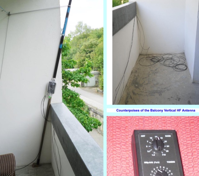 The simple balcony vertical HF antenna made with plastic fishing pole. Just along the pole I install copper wire in 7 meter length. Then was installed ATU. It was used home brew tuner. For each band was used one counterpoise in length 0.8 x lambda/4
 -
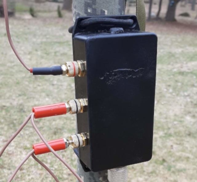 In the quest for an ideal field portable antenna, the author recounts experiments involving various wire configurations. While a previous candidate, a 41ft random wire, proved effective but lacked stealth, the search led to a surprising rediscovery of a design previously rejected—the Rybakov Antenna. With a focus on simplicity, rapid deployment, and multiband capability, the author explores the versatility of a 26ft Rybakov, avoiding the halfwave trap. The article delves into the antenna's performance and its potential as a discreet, resonant solution for field operations, addressing the challenges encountered during a POTA activation. Additionally, the Unun/Balun design used in conjunction with the Rybakov Antenna is discussed, providing insights into achieving a balanced system.
 -
 Operating from Banana Island, Sierra Leone (AF-037), the 9L2019 DXpedition by F6KOP and a ten-operator team used the callsign 9LY1JM from January 9-21, 2019. This detailed report covers the logistical challenges, including securing visas and licenses with local assistance from Mark 9L1YXJ and Gregory of Dalton’s Guest House. The team deployed monoband quarter-wave verticals on the beach and two Beverage on Ground (BOG) antennas for Europe/Asia and the USA, operating four stations simultaneously. Technical hurdles encountered included high tides submerging antennas, requiring repositioning, and persistent QRM between closely spaced stations, mitigated by doubling filters. CW signal irregularities at 30-32 WPM were resolved by PC and WINTEST restarts. A significant FT8 logging bug was identified and corrected with on-site software. Despite these issues, the team logged over 4,000 QSOs in the first 24 hours, averaging 5,000 QSOs daily, with a peak of over 6,000 in one day. Propagation varied, with excellent 160m conditions on January 12 yielding over 750 QSOs, and a later four-hour opening pushing the 160m total past 1,600. High bands were challenging due to low solar activity, but mid-bands provided intense pileups and rapid continent-wide contacts. The DXpedition concluded with nearly 50,000 QSOs, including a successful school QSO with Collège Doisneau de Sarralbe (57), managed by F1ULQ and F6KFT.
 -
 A homebrew spectrum analyzer, the Specan, provides a crucial measurement capability often missing from the typical amateur radio shack, allowing for detailed analysis of RF signals up to 70 MHz. This double-conversion superheterodyne receiver design incorporates 112 MHz and 12 MHz intermediate frequencies, utilizing an _Si570_ as the local oscillator for fine tuning down to 1 Hz steps. It offers two resolution bandwidths: 300 KHz for broad spectrum sweeps and 1 KHz for precise close-in distortion measurements, achieving an 80 dB spur-free dynamic range at 1 KHz resolution. The project, a reboot of the classic _W7ZOI/K7TAU_ design from November 1998 QST, integrates an _Arduino_ microcontroller for controlling the Si570, managing a front-panel LCD, and communicating with a PC for spectrum plotting. This approach significantly reduces cost compared to commercial units, making advanced RF diagnostics accessible to homebrewers. The Specan can measure carrier suppression, VFO cleanliness, antenna VSWR, transmitter harmonics, and filter passband shapes, providing insights beyond what an oscilloscope or frequency counter can offer. Construction emphasizes modularity and careful shielding, with each stage built and tested individually on unetched copper clad board. The design includes detailed instructions for integrating the Arduino, building the Si570 oscillator, and aligning the various modules, often using the Specan itself for calibration. It requires a well-regulated linear power supply and can be built with common tools and readily available components, making it a practical and rewarding endeavor for those looking to enhance their RF test bench.
 -
 The E6AF DXpedition to Niue (OC-040) in 2019 successfully activated a rare DXCC entity, providing thousands of contacts for the global amateur radio community. Operations focused on maximizing QSOs across various **HF bands** and modes, significantly contributing to the DXCC program. The team, led by SP9FIH, meticulously planned antenna deployments and station setups, including a specific focus on **Fox-Hound mode** for digital operations, to ensure robust signal paths and efficient pile-up management. Operational details included specific schedules for CW, SSB, and digital modes, aiming to accommodate different time zones and propagation windows. QSL information and log search functionalities were made available post-operation, facilitating confirmation for thousands of contacts. The expedition encountered logistical challenges, including power supply failure and strict COVID-19 travel restrictions that delayed licensing. Despite these hurdles, the E6AF and E6CI stations provided valuable contacts from Niue, a sought-after location for many DXers.
 -
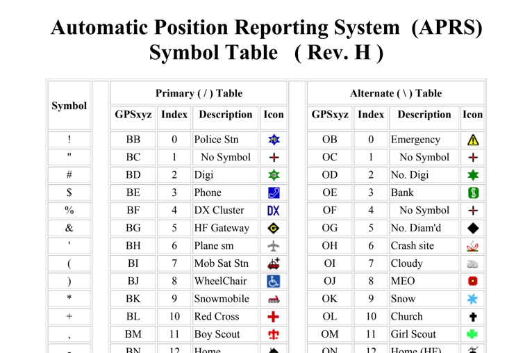 The four-page _APRS Symbol Table_ (Revision H) systematically lists 96 primary and 96 alternate Automatic Packet Reporting System symbols, each with its corresponding GPSxyz Index, a concise description, and a visual icon. For instance, the primary symbol '!' (GPSxyz BB) represents a "Police Stn," while its alternate counterpart '!' (GPSxyz OB) signifies "Emergency." The resource clearly delineates how specific ASCII characters map to distinct graphical representations on APRS displays, crucial for accurate situational awareness. It presents a direct, tabular format, making it an efficient reference for operators needing to quickly identify or interpret the myriad of icons used in APRS mapping applications. The table covers a broad spectrum of common APRS entities, from fixed stations like "Digi" (#) and "Home" (-) to mobile units such as "Car" (>) and "Plane sm" ('), alongside various weather phenomena and emergency services. Compiled by VK4KTP and featuring images by WA8LMF, the document serves as a definitive guide for understanding the visual language of APRS. It is particularly useful for those involved in tactical communications, public service events, or general APRS tracking, ensuring consistent symbol interpretation across different platforms and user interfaces.
 -
 WB5NHL describes setting up a 160-meter antenna on a small suburban lot, where standard options like Beverage antennas and 1/4 wavelength verticals require extensive space and ground systems. Instead, Guy Olinger's Folded Counterpoise (FCP) provides a solution. The FCP minimizes ground losses by using a folded wire design, allowing effective antenna placement in limited space. The FCP, fed with an isolation transformer, enabled WB5NHL's first 160-meter antenna installation, offering improved performance despite space constraints.
 -
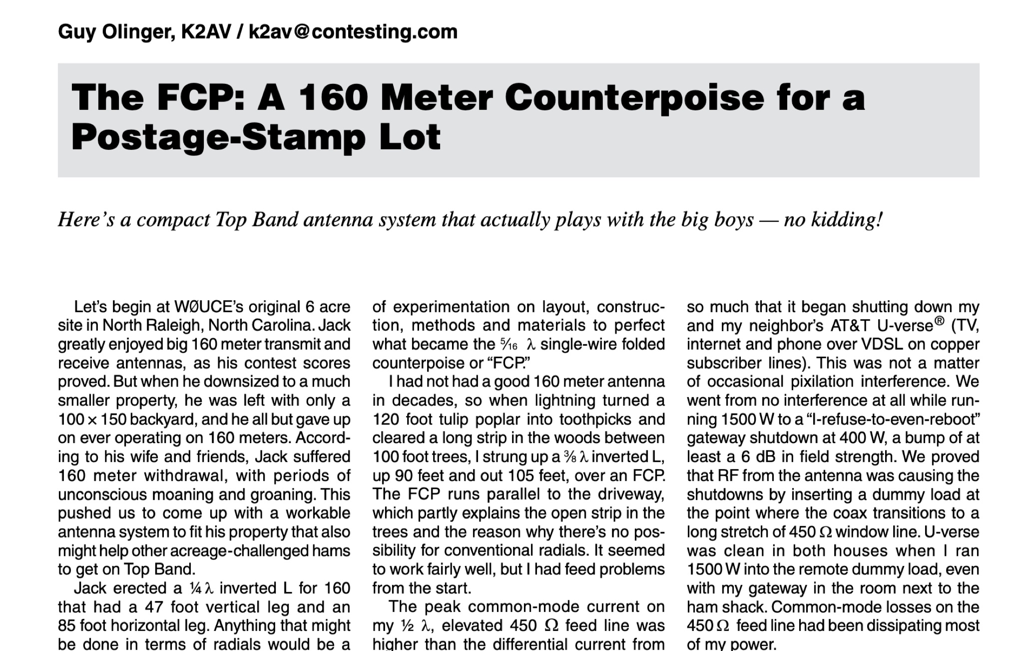 The article by Guy Olinger, K2AV, published in the May/June 2012 National Contest Journal, introduces the Folded Counterpoise (FCP), a compact 516-foot single-wire counterpoise elevated at 8 feet, designed for 160-meter operations on small lots like 100x150-foot backyards. Originating from efforts to revive Top Band for W0UCE on a postage-stamp property, the FCP uses strategic folds to cancel ground fields within 33 feet of center, minimizing losses to 0.13-0.53 dB—outperforming sparse or on-ground radials by up to 15 dB in poor soil—while mimicking opposed radials for efficient feedpoint impedance. Paired with a critical 1:1 or 4:1 isolation transformer (e.g., trifilar on T300-2 toroid) to block common-mode currents on coax feeds, it delivers proven results: K2AV's #8 North America low-power contest score, 7+ dB gains at W4KAZ and K5AF, and over 10,000 global web hits for DIY instructions using bare 12 AWG wire and weatherproof enclosures. Ideal for acreage-challenged hams, the FCP also excels on 80 meters with scaled dimensions, offering a low-loss alternative where full radials are impractical
 -
 Improve the FRG-7 operation adding a home made digital frequency display. The author explains the challenges of using the analogue dial on the FRG-7 and how a digital display can be a useful solution. The page provides detailed information about the FRG-7's design and frequency conversion process. It also includes step-by-step instructions on how to connect an external frequency counter to display the kHz part of the frequency.
 -
 VE1ZAC's analysis details the performance of **MFJ927** and **SGC239** autotuners with portable HF vertical antennas, specifically comparing 31 ft and 43 ft configurations. The resource originated from challenges encountered during a Maritime QSO Party roving operation, necessitating a lightweight and easily deployable antenna system. Target bands for the contest included 80, 40, 20, 15, and 10 meters, with a maximum power handling of 100 W CW. The author utilized a 30-foot carbon fiber push-up pole to support a vertical wire element, noting its 2 lb weight and reliability. EZNEC modeling was employed to predict performance, showing favorable results for a 30-foot vertical with elevated radials, particularly on 40 and 20 meters. Feedpoint impedance measurements, taken with an AIM4170C, are presented for various HF bands, both with and without a 41-foot RG6 stub designed to reduce reactance on 80 and 20 meters. The stub significantly improved matching on these bands, easing the tuner's workload. Operational tests revealed issues with the MFJ927's reliability during contest setup, leading to reliance on the K3's internal tuner. The SGC239, tested post-contest, performed flawlessly. A detailed side-by-side comparison covers mechanical aspects, connection options, power bias, impedance range, board quality, and documentation. Modifications to the MFJ927, including a new aluminum case, white paint for heat reduction, and upgraded impedance-measuring resistors, are also described.
 -
 This report details a modification of a Diamond V2000 antenna, replacing its original two 0.50 m radials with two 1.55 m radials. Initial M5-threaded rods failed to fit; the housing required M6 threads. Custom radials were made using 8 mm OD aluminium tubing and M6-threaded stainless steel ends, secured with nuts machined to 9 mm. SWR issues on 6 m (>2:1) were largely due to a poor counterpoise connection, resolved during reassembly. NanoVNA measurements showed no adverse effects on 2 m or 70 cm. The final setup retains the two 1.55 m radials and original counterpoise. Other operators reported SWR degradation with similar mods—sometimes fixed by adding capacitance—but this was not observed here.
 -
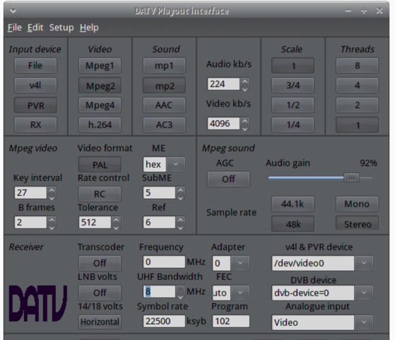 The ZL1WTT resource details an experimental software-based Digital Amateur Television (DATV) system, demonstrating the multiplexing of up to six standard-definition (SD) and one high-definition (HD) channel utilizing _h264 compression_. The author encountered peak data rates reaching 32 Mbit/s, necessitating a shift to Freeview and Sky settings (22.5M Sym/s 3/4FEC) to manage bandwidth. The setup employs four networked computers, with a laptop functioning as the multiplexer to re-code PIDs for various inputs, including looped MPEG2 playlists, MPEG2 encoder card input from a VCR, satellite feeds, and an off-air UHF receiver. The system highlights the inherent flexibility of the DVB transport stream, supporting diverse formats such as MPG2, h264, AC3, and AAC. A significant advantage of this software-defined approach is the absence of video quality degradation from stored MPEG2 files to the displayed output, coupled with the ease of reconfiguring settings for MPEG2 encoder cards (e.g., size, bit-rate, frame rate, video input, coding format) and satellite receiver cards (e.g., frequency, LNB volts, symbol rate, FEC). The author also discusses the development of a new graphical user interface (GUI) using _Gambas_ for Linux, aiming to simplify configuration for this DATV project. Specific hardware components mentioned include Hauppauge WinTV PVR-150 and Nova-S plus cards, with a focus on optimizing analog video input via Y/C (S-video) to minimize frequency roll-off. The resource also provides insights into data rates for HD (1080i) content, recommending 8 to 12 Mb/s for optimal performance. Software utilized includes _Ubuntu Studio 10.04_, WinFF, VLC, and TMPGEnc Editor, underscoring the project's reliance on open-source tools and a foundational understanding of LAN networks and DVB transport streams.
 -
 Operating amateur radio satellites presents unique challenges, particularly concerning antenna design and signal propagation. Juan Antonio Fernández Montaña, EA4CYQ, recounts his three-year journey into satellite communication, starting with initial guidance from EB4DKA. His early experiments involved a portable 1/4 wave VHF antenna with four 1/4 wave ground planes, designed for hand-held use to adjust polarity. This setup, paired with an FT-3000M transceiver, allowed full-duplex operation on **VHF** transmit and **UHF** receive, proving effective for early contacts on satellites like AO27, UO14, and SO35. EA4CYQ's experience highlights the critical role of coaxial cable loss and antenna polarization. After encountering significant signal degradation with longer RG213 runs, he experimented with a 1/2 inch commercial cable, noting improved reception but persistent fading due to varying satellite polarities. This led to the construction of an **Eggbeater II** antenna, an omnidirectional UHF design offering horizontal polarization at the horizon and circular right polarization at higher elevation angles. Subsequent modifications resulted in the directional **TPM2** antenna, which provided sufficient gain for LEO satellites with a wide 30-degree lobe, enabling consistent contacts from his home station. The article concludes with practical insights on the performance of the Eggbeater II for both UHF and VHF, and the TPM2 for UHF, emphasizing their utility for portable and fixed operations. EA4CYQ's journey underscores the iterative process of antenna development and the importance of adapting designs to overcome real-world propagation challenges in satellite communications.
 -
 Details the construction and performance of a phase-controlled receiving array, specifically a **MicroSWA** variant, optimized for QRP low band fox hunting on 40M and 80M. The resource documents the author's iterative design process, addressing significant regional noise challenges encountered during 0100-0230 UTC fox hunt periods. Initial experiments involved a director wire on a 40M vertical, yielding limited improvement, prompting a shift towards advanced null-steering techniques. The project leverages concepts from Victor Misek’s "The Beverage Antenna Handbook" and Dallas Lankford’s extensive work on phased receiving antennas for urban lots. A key modification involved integrating a new passive phase control box and a push-pull **Norton common base preamp** using 2N5109 transistors, designed for high third-order intercept performance to maintain weak signal integrity amidst strong adjacent signals. The system incorporates Faraday-shielded transformers with RG174 primaries on -75 ferrite cores, housed in ABS plastic pipe. Performance tests confirmed the MicroSWA's ability to produce deep, steerable nulls, achieving approximately 30 dB noise reduction on 160M, 80M, and 40M. This enabled detection of QRP signals undetectable on conventional transmit antennas. The final unit includes front panel controls, a 10-11 dB preamp, and a robust power conditioner, demonstrating effective noise mitigation for challenging low band QRP operations.
 -
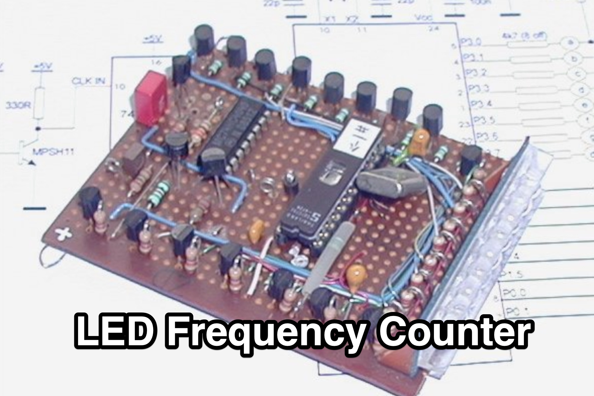 This page provides an introduction to the ZL2PD LED Frequency Counter. It covers the design, construction notes, and downloads related to the project. Created by Andrew Woodfield, ZL2PD, this resource offers valuable information for hams interested in building their own frequency counter using LEDs. The content is dated June 12, 2010, with a revised version 2.0. The page also credits the template design by Andreas Viklund.
 -
 TX5EU 2026 DXpedition to Raivavae Island, **OC-114**, within the Austral Islands, providing a detailed account of the German/Dutch team's operations. The resource outlines the participation of operators such as DL2AWG Guenter, PA2KW Evert, and DK2AMM Ernoe, who engaged in CW, SSB, RTTY, and various digital modes. It documents the real-world challenges encountered, including significant equipment failures and antenna damage to 80/60m, 30m, and 10m verticals due to adverse storm conditions. The page offers timely news updates on the expedition's progress, noting repairs to a power amplifier's 10/12m bandpass filter, which enabled three stations to utilize amplification. Earlier reports highlighted power failures and the loss of multiple power amplifiers, necessitating one station to operate barefoot FT-8 with 100W. The team's persistent efforts to repair antennas as weather permits are also detailed, reflecting the dynamic nature of remote island operations.
 -
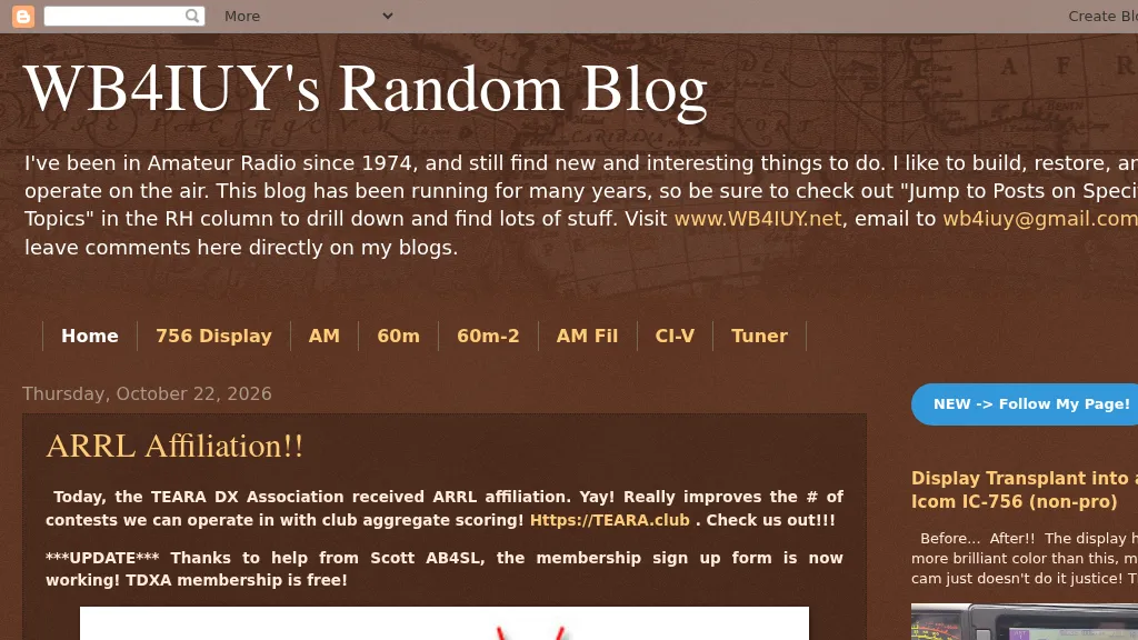 WB4IUY's Random Blog chronicles the author's extensive experience in amateur radio, spanning since 1974. The content primarily focuses on the restoration, building, and repair of radio equipment and amplifiers, alongside various other related projects. Readers can navigate through years of accumulated posts by utilizing the "Jump to Posts on Specific Topics" feature located in the right-hand column. The blog serves as a repository for practical knowledge and hands-on experience, detailing specific technical challenges and solutions encountered during equipment overhauls. It provides a historical perspective on amateur radio gear, offering insights into maintaining and extending the operational life of vintage and modern transceivers. The author, WB4IUY, shares personal projects and technical observations, fostering a community resource for fellow hams interested in the technical aspects of the hobby.