Search results
Query: power o
Links: 261 | Categories: 34
This query is too generic. Please try adding an additional term to focus your research.
Categories
- Shopping and Services > Alternative Power
- Manufacturers > Alternative Power
- Technical Reference > Alternative Power
- Manufacturers > Test Equipment > Power Meter
- Technical Reference > Power Meter
- Manufacturers > Power Supply
- Technical Reference > Power Supply
- Manufacturers > Accessories
- Radio Equipment > HF Amplifiers > Alpha 8410
- Radio Equipment > HF Amplifiers > Ameritron AL-80B
- Manufacturers > Amplifiers
- Shopping and Services > Batteries
- Technical Reference > Batteries
- Technical Reference > Radio Frequency Interference > BPL
- Manufacturers > Cable and Connectors
- Technical Reference > Dummy Loads
- Manufacturers > Lightning and Surge Protection
- Operating Modes > Lora and Mesh
- Radio Equipment > Antenna Tuners > MFJ-989C
- Software > Oscilloscope
- Technical Reference > Radio Frequency Interference > PLT
- Manufacturers > Alternative Power > Portable Generators
- Operating Modes > Portable Operations
- Operating Modes > QRP
- Ham Radio > Clubs > Technical Specialty > QRP Clubs
- Technical Reference > QRP Projects > QRP CW Transceiver
- Manufacturers > QRP Kits
- Technical Reference > QRP Projects
- Radio Equipment > VHF-UHF Amplifiers > RM VLA-200
- Manufacturers > Alternative Power > Solar Panels
-
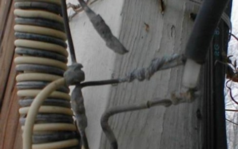 I built a homebrew 75 meter Double Extended Zepp Antenna, And I needed a 4:1 Balun So I decided to Homebrew the Balun also. Here is how I did it!
-
 Details the history and product focus of RM Italy, an Italian manufacturer specializing in radio communication devices since 1974. It outlines the company's journey from its founding by Remo Marchioni in Porretta Terme, Italy, to its current position in the market, emphasizing its commitment to high-quality, competitively priced products. The resource highlights RM Italy's core product lines, which include RF power amplifiers for various bands such as HF, CB, VHF, and UHF, alongside power supplies and DC-DC converters. It also mentions the company's involvement in _ISM products_, indicating a broader application of its radio technology beyond amateur radio. The page underscores the company's strategic approach, focusing on a modern manufacturing structure and an effective sales network to deliver reliable products and strong after-sales support. The company's amplifiers are known for providing significant power output, with some models offering **up to 600W** on HF, catering to both amateur and professional radio operators seeking robust signal amplification.
-
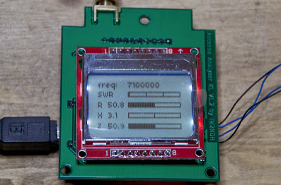 The project details a DIY SWR/Wattmeter designed around an _Arduino Uno_ shield, providing capabilities to measure RF power from 2 to **200 watts** and Standing Wave Ratio (SWR) for HF amateur radio bands. This construction features a compact design, integrating the measurement circuitry directly onto a custom PCB that interfaces with the Arduino Uno microcontroller. Key components include a directional coupler for sensing forward and reflected power, precision rectifiers, and analog-to-digital conversion for processing RF signals. The Arduino firmware handles calibration, calculations, and displays the results on an integrated LCD, offering real-time feedback on antenna system performance. The design prioritizes simplicity for homebrewers. Performance specifications indicate accurate readings within the **2-200W** power range, suitable for typical QRP to medium-power HF operations. The project provides schematics and a basic overview of the software logic.
-
 A 20 ampere and more 13,8V power supply for RTX
-
 Project for a 12 volt, 30 ampere Power Supply Unit
-
 Alinco's factory in Toyama, Japan, holds ISO9002/140001 certification, underscoring its commitment to quality manufacturing processes for amateur radio equipment. The company produces a diverse range of products, including HF transceivers, mobile VHF/UHF radios, handhelds, and scanners, serving both new and experienced operators within the ham radio community. Their product line extends beyond transceivers to encompass essential accessories such as antenna tuners and power supplies, which are crucial for complete station setups. These offerings support various operating environments, from portable field operations to fixed home stations, ensuring versatility for radio amateurs. Alinco, Inc. Electronics Division is headquartered at Yodoyabashi Dai-Bldg 13F, 4-4-9 Koraibashi, Chuo-ku, Osaka 541-0043 Japan, maintaining a global presence in the amateur radio market.
-

-

-
 This homebrew legal-limit antenna tuner is based on the famous "Ultimate Transmatch" introduced by the late Lew McCoy, W1ICP. The Ultimate Transmatch was described in the "Beginner and Novice" section of the July 1970 QST (Page 24).
-
 The _Astron RS35m Power Supply Schematic_ provides a detailed circuit diagram for this popular linear power supply, focusing on the rectifier and pass transistor stages. It presents the AC input and DC output sections, illustrating the component layout and interconnections critical for understanding its operation. The schematic is enhanced with specific annotations derived from the December 2005 QST "Hands-On Radio, Experiment #35 Power Supply Analysis." These notes offer insights into the circuit's functionality and potential analysis points, making the diagram more instructive than a bare schematic. The resource serves as a practical reference for hams interested in the internal workings or maintenance of the _Astron RS35m_ unit. This document specifically highlights the key components responsible for voltage regulation and current delivery.
-
 Strong RF HF power amplifiers made in europe ! Output 2,5KW 4KW PEP, 160m to 10m.
-
 Two types of home-brewed 12/20 Ampere 13,8volt power supplies, including detailed part lists by ON6MU
-
 A 13,8v/5Amp 78H05 based power supply for portable use. In this example used to power up a Yaesu FT-817
-
 Dchematics and photos of a secure power supply (short-cut, Rf feedback, high voltage etc.) by iz7ath
-
 This project uses a widely available IRF510 MOSFET, work on HF 80, 40, 30, 20 and 17 meter bands
-
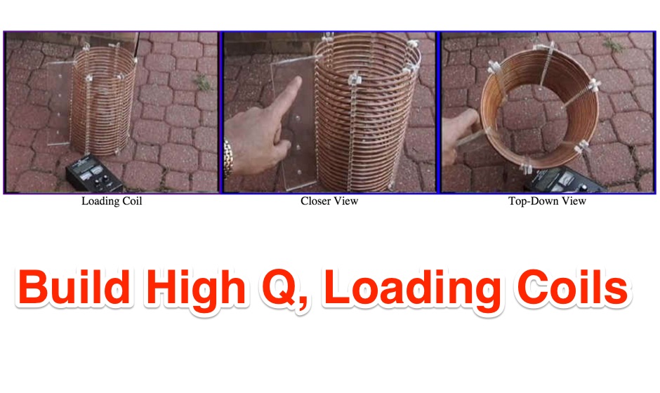 This page describes the loading coil (inductor) that W8WWV built for my center-loaded 160 meter band (1.83 MHz) vertical antenna.
-
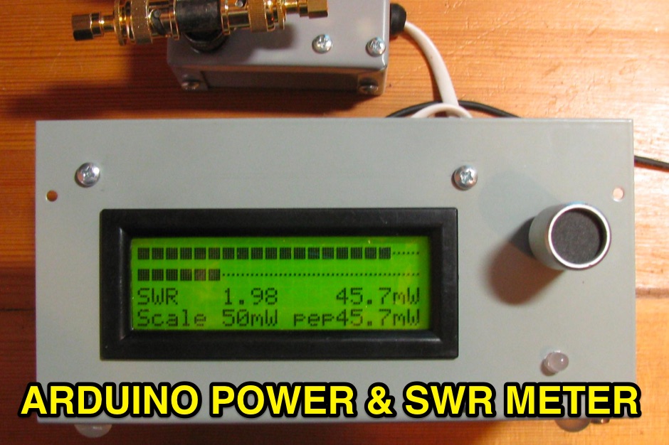 Power and SWR Meter with dual bargraphs and sticky bar, using 2x AD8307
-
 The article details antenna tuning procedures, emphasizing SWR measurement and adjustment for both mobile and base station setups. It explains that SWR (Standing Wave Ratio) is the ratio of transmitted power to reflected power, with high SWR indicating poor impedance match and potential damage to a transceiver's final amplifier. Specific instructions are provided for CB antennas operating between 26-27 MHz, recommending initial SWR checks on channels 1, 20, and 40 to determine if the whip needs shortening or lengthening. Adjustments should be made in small increments, approximately 1/4 inch at a time, aiming for an SWR of 1.5:1 or better. For _Ham radio_ and other antennas, the same tuning principles apply, with a strong caution regarding RF energy exposure when operating at higher power levels. The resource suggests tuning base antennas at ground or roof level before final installation to simplify adjustments. It also advises rechecking SWR after final installation to confirm no changes occurred. The _Alpha Rubicon_ resource highlights the importance of a good ground plane for mobile antennas and proper coax routing to avoid pinching or proximity to electrical wires.
-
 The KD1JV "Melt Solder" Digital QRP SWR/Power Meter operates across the 160m to 6m bands, featuring 9.9-watt and 990-milliwatt power scales, a peak hold mode for SSB, and a VSWR scale from 1:1 to 9.9:1. It utilizes a _Stockton directional coupler_ wound on a single binocular core and an _Atmel AVR ATtiny26L_ microcontroller for processing. The design incorporates _W7EL diode compensation_ in a non-inverting amplifier feedback loop to address diode voltage drop and non-linear behavior at low power levels, with software corrections applied for improved accuracy, particularly at QRP power levels up to 5 watts. Construction details include parts placement, transformer winding instructions for #26 magnet wire, and calibration procedures using a 1.5V alkaline battery or an oscilloscope with a 50-ohm dummy load. Packaging options are discussed for fitting the board into an Altoids tin or a deeper Whitman’s Sampler tin, with considerations for battery life extension by adding a third or fourth battery. Accuracy tests performed at 7 MHz compare readings against a True RMS power meter based on an _Analog Devices AD8361_ chip, showing typical deviations of 0-5% across various power levels.
-
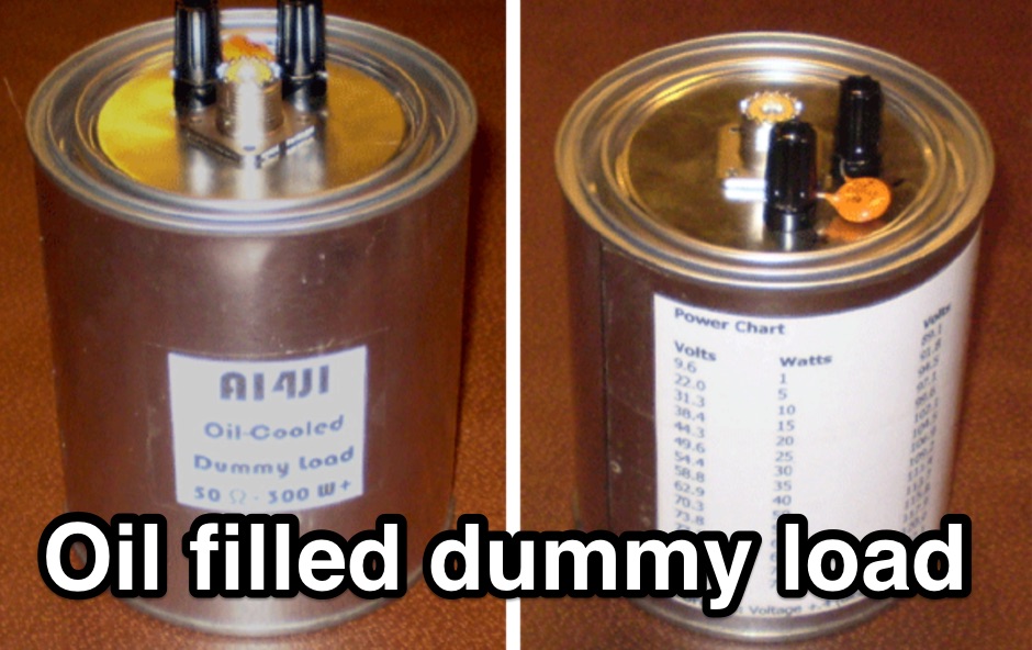 This project shows how to build a 50-ohm dummy load using non-inductive resistors, oil for heat dissipation, and a simple assembly process. It enables accurate transmitter tuning, testing, and power measurement across LF to UHF bands. The setup allows meter calibration by measuring peak voltage, applying diode drop correction, and calculating RMS voltage and power precisely. Parts are inexpensive and widely available. With proper assembly, this dummy load offers extended service life, accurate readings within 2%, and a reliable alternative to costly commercial wattmeters for amateur radio applications.
-
 University of Texas Amateur Radio Club RF-Calculator. This is a main beam power density estimation program intended for use as part of a routine evaluation of RF safety compliance with FCC regulations
-
 AM/FM/CW QRP RF Power Amplifier for the HF 10 or 11 meterband (28MHz/27MHz)
-
 1500 Watt HF power amplifier
-
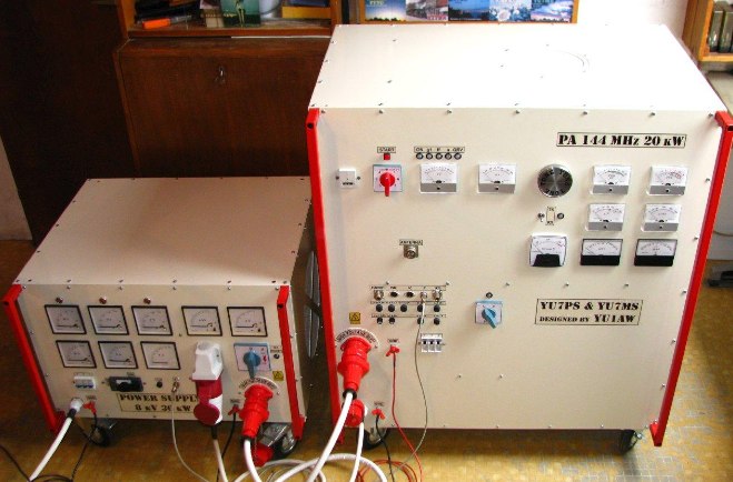 YU1AW project for a home made QRO PA 144 MHz 20 kW GU36B-1
-
 Based on VK5BR's Z-Match and designed for High RF Power covers 160 to 10 meters by VK6YSF
-
 A PIC16F876 microprocessor-based digital SWR/WATTmeter project provides automatic operation across the 1.8 to 60 MHz frequency range. This design displays both SWR and P.E.P. power values, incorporating a bar graph on the second LCD line for instantaneous power tracking. The directional coupler utilizes a single-wire coil on a ferrite FT50-43 toroid, balanced with a 60 pF trimmer, and employs 1N5711 Schottky diodes for detection, ensuring linearity and a power range of 5 to 120 W. The software, developed by IW3EGT, compensates for diode voltage drop for precise readings, updating power every two seconds for stable display of modulated carriers, while the bar graph updates ten times per second for near real-time feedback. Calibration involves two phases: adjusting the directional coupler for minimum SWR on a 50-ohm dummy load at 28 MHz, and calibrating the microprocessor system by inputting a calculated power value (Power (Watt) = (Vout + 0.5)^2 / 100) at 14-21 MHz. The project includes PCB layouts for both the directional coupler (two-layer copper board) and the PIC module (single-sided), with specific instructions for component placement and shielding to prevent RF interference. The design allows for modification of power reading capability by varying the number of turns in the coupler coil, catering to different power levels.
-
 SWR and RF power meter for home usage, 8 different RF probes with different characteristics and power ranges by OK1DX
-
 Contruction manual to build a 4:1 balun, it has good performance from 160 through 10 meters.
-
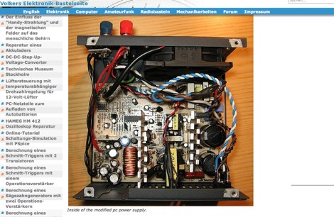 Converting Computer Power Supplies (PSU) to stabilized 13.8 V DC 20 A
-
 Gi7b is tube designed for microwaves but working good as HF amplifier. Idea is to build cheap, reliable HF amplifier covering 160 meters band.
-
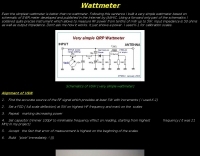 Details a practical QRP wattmeter construction, leveraging a simplified SWR meter design by JA6HIC. The project focuses on a forward-only power measurement circuit, providing a functional instrument for RF power levels from milliwatts up to 5 watts. It maintains a 50-ohm input and output impedance, suitable for typical QRP transceivers and antenna systems. The resource includes the schematic for the "VSW" (Very Simple Wattmeter) and outlines a six-step alignment procedure. This calibration process involves using a known RF source up to 5W, setting full-scale deflection, and marking power increments. It also addresses minimizing frequency effects on readings with a 100pF trimmer capacitor, noting that measurement error is highest at the lower end of the scale. Construction notes mention using a piece of RG-213 coaxial cable for the inductance and coupler, with the wattmeter assembled in early 2003. The author provides an example measurement showing 0.8W into a dummy load and 1W into a 3-element beam.
-
 Over 75 years of engineering expertise underpins Bird Electronic's offerings in RF power measurement, critical for maintaining peak performance in amateur radio stations and professional communication systems. The company specializes in a range of test equipment, including wattmeters, SWR meters, and antenna analyzers, essential for optimizing antenna systems and ensuring efficient power transfer. Their product line extends to various RF components such as filters, cables, and connectors, all designed to meet stringent technical specifications for reliability and accuracy across diverse frequency bands. Bird Electronic's instruments, like the _Bird 43_ Thruline Wattmeter, are widely recognized for their robust construction and precise measurement capabilities, providing hams with confidence in their station's operational parameters. These tools enable accurate assessment of forward and reflected power, SWR, and modulation characteristics, which are vital for troubleshooting and maximizing radiated power. The company's commitment to innovation ensures that its products remain relevant for modern RF challenges, from HF through microwave applications, supporting both traditional analog and advanced digital modes.
-
 PC power supply conversion for ham radio use. Slide show overview showing how convert PC Power supplies to ham radio use presented at the August 2007 FSARC meeting.
-
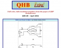 Build a Low Power 4:1 Balun , by Charles Greene, W1CG with full-color, full-resolution graphics from the pages of QRP Homebrewer
-
 Presents Mr. Coily, a manufacturer specializing in custom-built base and mobile antennas for amateur radio and CB applications. The product line features unique coil designs, including single, double, and triple coil configurations, alongside flat coil options. Dan is listed as the contact for inquiries regarding these specialized antenna solutions. The resource highlights custom ball mounts as an accessory, indicating a focus on tailored installations. While specific technical specifications or performance comparisons are not detailed, the emphasis on custom builds suggests a service catering to operators seeking bespoke antenna solutions for their particular station or mobile setup.
-
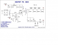 80m hexfet power amplifier by W7ZOI
-
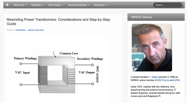 Rolling your own transformers and chokes. Rewinding salvaged power transformers, considerations and step-by-step guide
-
 13.8 V / 15 A from a PC Power Supply in German
-
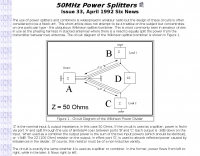 Splitting an antenna between two receivers or in use as the phasing harness in stacked antennas where there is a need to equally split the power from the transmitter between two antennas
-
 20/22 Ampere or 30/32 Ampere 13.8 volts power supply RE-PSF14A20 or PSF14A30 by ON6MU
-
 Comtech PST offers solid-state power amplifiers in frequency ranges from 1 MHz through 3.6 GHz, with output power levels ranging from 5 watts to over 30 kW
-
 How to homebrew an hex beam antenna for 20 17 15 12 10 meters band by VA7ST
-
 We offer a large selection of standard and custom High Power RF and Microwave amplifiers for broadband, general communication, matched band, and personal communication markets.
-
 The 20m monoband 4-1000 amplifier, by Jelmer (pa5r), Herman (pa0ten) and Frans (pa5ca)
-
 What do you do with a bunch of old computer power supplies?
-
 Engaging in **QRP** operations, where amateur radio transceivers transmit at five watts or less, presents a unique challenge and satisfaction for many radio amateurs. This mode emphasizes efficient antenna systems, keen operating skills, and often, the art of **homebrewing** equipment to maximize performance under power constraints. Operators frequently utilize CW (Morse code) for its superior signal-to-noise ratio, enabling reliable contacts over long distances with minimal power. The VK QRP Club, formally known as the CW Operators' QRP Club Inc., serves as a focal point for Australian amateurs passionate about these low-power pursuits. The club fosters a community where members can share insights on antenna design, circuit construction, and operating techniques specific to QRP. It provides resources such as information on club nets and frequencies, Morse practice materials, and a platform for exchanging ideas among enthusiasts. Membership offers access to a network of like-minded individuals, promoting the continued development and enjoyment of QRP within the amateur radio hobby. The club's activities encourage experimentation and skill refinement, vital aspects of successful low-power communication.
-
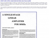 G3WZT design for a single stage bi-polar 100-150W Linear Power Amplifier for the 6M band.
-
 Manufacturers of high performance low power am transmitter products: sstran amt3000, bc-100, and the mw-250. for home and professional use.
-
 The Q-signal **QRP** signifies a request to reduce power, and in amateur radio, it defines operating with 5 watts or less for CW and 10 watts or less for SSB. This article addresses common inquiries from new hams regarding the practice, its benefits, and implementation methods. It explains how a 5-watt QRP signal, compared to a 100-watt signal, typically results in only a 13dB drop in signal strength, equating to about two S-units, still providing solid copy under most conditions. Hams choose QRP for various reasons, including seeking a greater challenge in DXing or contesting, reducing band interference, or enabling portable field operations with lightweight, battery-efficient equipment. A modern single-band CW transceiver, key, and antenna can fit into a pocket, offering receiver performance comparable to commercial rigs and extended operation on a small battery. This portability facilitates operations in remote locations where higher-power setups are impractical. Operating QRP can involve simply reducing power on an existing commercial HF rig or building a dedicated QRP transceiver from a kit, such as the **Wilderness Radio SST** with its 2-watt output and 15mA receive current draw. While SSB is viable, CW remains the most popular and efficient mode for QRP due to its superior signal-to-noise ratio. The article lists common QRP calling frequencies across 160m through 10m bands for both CW and SSB, and highlights organizations like QRP ARCI and NorCal that support the QRP community.
-
 Need a variable power supply that is short circuit protected and over voltage protected; Here is a good one that can be built cheap by VE3IVJ