Search results
Query: vk6ysf
Links: 25 | Categories: 0
-
 Antenna suitable for all the HF amateur bands, including the so called WARC bands by vk6ysf
 -
 Based on VK5BR's Z-Match and designed for High RF Power covers 160 to 10 meters by VK6YSF
 -
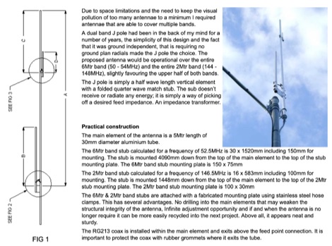 Dual band J pole operational over the entire 6Mtr band (50 - 54MHz) and the entire 2Mtr band (144 - 148MHz), slightly favouring the upper half of both bands by VK6YSF
 -
 146MHz 5/8 ground plane tower mounted antenna. The antenna was largely based information and analysis provided by the RSGB's. VHF UHF Manual, fourth edition by G.R.Jessop, G6JP
 -
 The Super J Pole antenna is a co-linear vertical consisting of a number of half wave length vertical elements separated with half-wave length stubs (Tuning stub) feed with a folded matching stub by vk6ysf
 -
 Presented here is a transceiver to computer sound card interface complete with automated transmit key function. A sound card interface is simply the audio coupling of a computer soundcard and a transceiver to allow various computer applications that send and receive SSTV, RTTY, PSK31 and other similar modes based on soundcard generated signals.
 -
-
 All Band HF Doublet for operation over all HF bands including 160m.
 -
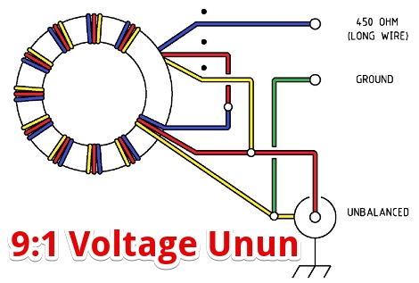 A 9:1 voltage unun using a T-200-2 powdered iron toroid core to feed a long wire multiband antenna.
 -
 1:1 Ruthroff voltage balun using a T200-2 Toroid core
 -
-
 One point eight MHz to 30 MHz is the operational bandwidth for this 4:1 Ruthroff voltage balun, designed to interface an unbalanced T-Match network with a balanced antenna system. The project details the construction using a _T200-2_ powdered iron toroid core, tightly wrapped in PVC electrical tape for insulation, and wound with 17 double bifilar turns of 1.25mm enamelled copper wire. This outboard balun offers flexibility, allowing hams to trial various baluns based on antenna system and impedance characteristics, rather than integrating it directly into the tuner. The resource includes a schematic of the balun, a wiring diagram showing winding connections, and a table suggesting alternative toroid cores like the T80-2 or T400-2 with corresponding winding counts. Component sourcing is straightforward, listing items such as the _Amidon_ T-200-2 core, SO-239 connector, and a sealed polycarbonate enclosure from Jaycar. Performance evaluation was conducted using an _AIM 4170C_ antenna analyser, demonstrating efficient 1:4 voltage transformation across the specified HF spectrum. Further efficiency tests involved measuring RF power loss at various frequencies, revealing minimal loss—less than 0.7 dB from 3.6 MHz to 30 MHz, and only 2.0 dB at 1.8 MHz. These measurements, performed under ideal 50-ohm conditions, confirm the balun's effectiveness as a low-loss interface for multi-band antenna systems. The page also links to several other balun and unun projects, including 1:1 current and voltage baluns, and 9:1 voltage ununs, providing a broader context for impedance matching solutions.
 -
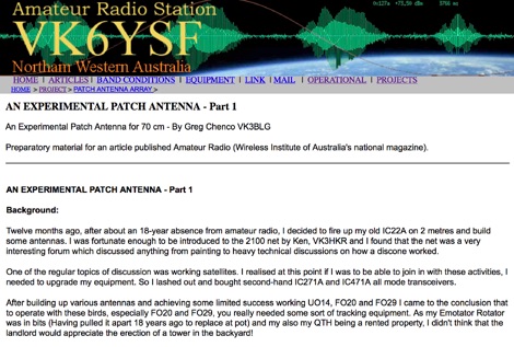 This web article by VK3BLG details the construction of an experimental 70cm (432 MHz) circularly polarized patch antenna, intended for satellite communication. The resource provides dimensions, feed point specifications, and impedance matching considerations for a single patch element, with discussion extending to array configurations for circular polarization. Construction involves a copper patch element on a dielectric substrate, fed via a coaxial cable. The design is based on information derived from AO-40 satellite antenna specifications, focusing on achieving circular polarization for satellite reception. The article includes specific dimensions for the patch and feed points, along with impedance values. Validation is implied through on-air satellite reception reports, with initial signal reports of **1 S-point above noise** for AO-40 beacons using a grid reflector, improving to **3-4 S-points above noise** with a 2-turn helical feed. The author references a _NanoVNA_ for impedance measurements and discusses the relationship between slot and dipole antennas in the context of patch design. DXZone Focus: Web Article | 70cm Patch Antenna | On-Air Satellite Reception | Circular Polarization
 -
 T-Match Network Antenna Tuner for a wide range of complex antenna loads between 1.8 and 30Mhz at moderate power levels by VK6YSF
 -
 With the view to establish a quick and easy multi-band antenna deployment for portable and camping operations a simple long wire antenna with an earth or earth plus counterpoise arrangement with a 9:1 voltage unun including a tuner or simply with a tuner is one possible solution. With the 9:1 voltage unun and wire lengths suggested in the below tables the antenna should present non extreme impedances for all HF amateur band frequencies. This page is far from complete and represents the ongoing investigation into this type of antenna. Experiments to date seem to have raised more questions than obvious answers.
 -
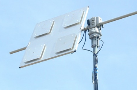 The Patch Antenna Array was constructed and used for various satellite up and down links at my previous residence in Melbourne, Victoria from 2003 - 2007
 -
 The past and future of the Sun's solar cycle and possible impact on the Earth's climate.
 -
 Brief overview of PSK31 and basic operating techniques.
 -
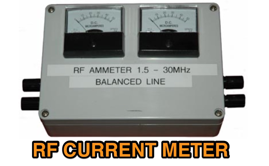 This R.F. current meter was developed to assist in measuring line currents in balance feed lines as used in the All Band HF Antenna.
 -
 The 40dB fixed attenuator is derived from two 20dB Pi attenuation pads
 -
 Amateur radio web site of Peter Miles , VK6YSF. The purpose of this site is to promote amateur radio and also as a way to document and share the various radio activities and projects that I'm involved with.
 -
 Presented is a historical collection of short-wave listening (SWL) QSL cards, primarily from the late 1930s and early 1940s, offering a glimpse into early international broadcasting and the technical pursuits of SWL operators like Les Miles during that era. The resource showcases specific QSLs from stations such as _Broadcasting Corporation of Japan_, _XGOY - The Central Broadcasting Administration_ in Chungking, China, and _Australian broadcasting ship, Kanimbla VK9MI_, each with reception dates and frequencies like 11.90MHz or 9.525MHz. It highlights the self-sufficiency of SWL enthusiasts who constructed and maintained their own radio and test equipment, evoking the sensory experience of vintage valve receivers. The collection provides concrete examples of international broadcast stations active before and during World War II, including _2RO3 - Rome_ and _WRUL - World Wide Broadcasting Foundation_ from Boston. Each QSL entry details the station, location, reception date, and often the frequency, such as 9.63MHz or 11.26MHz, allowing for historical verification of broadcast schedules. The resource also briefly mentions the operational details of the _VK9MI_ offshore radio station, directing readers to further information on its history. This compilation serves as a tangible record of global radio communication during a pivotal historical period.
 -
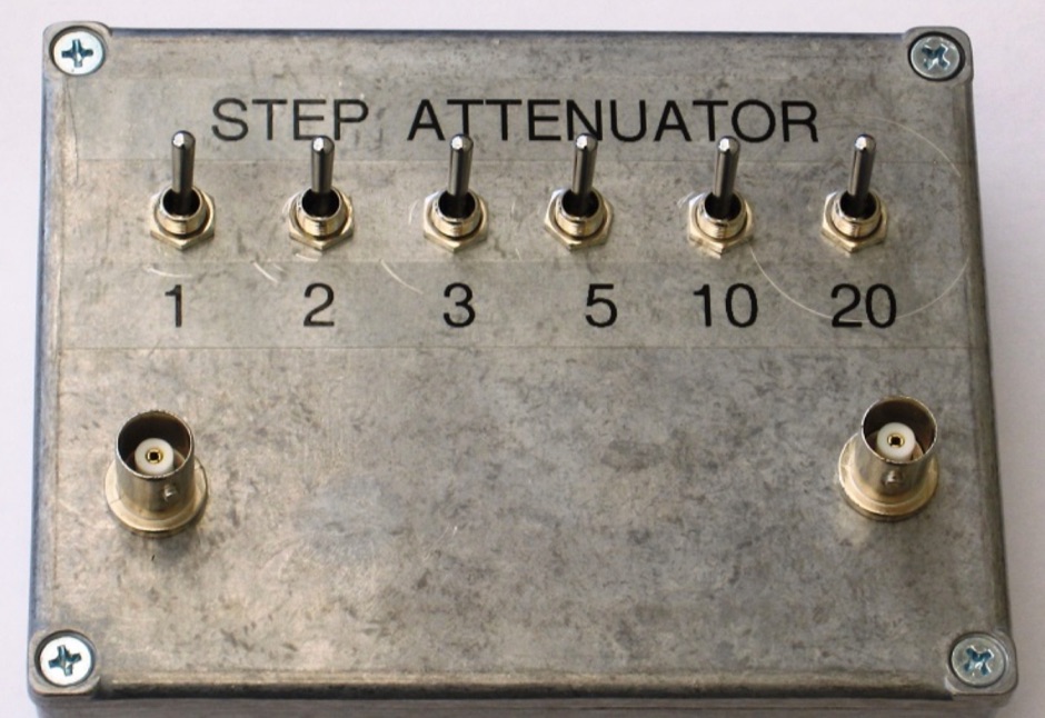 A 0-30 MHz step attenuator, constructed from switchable Pi attenuation pads, provides a practical tool for evaluating receiver sensitivity and calibrating S-meters. The design utilizes readily available 5% tolerance resistors, with values derived from paralleled components to achieve specific attenuation steps. A schematic (Fig 1) illustrates the circuit, including PCB pad shielding, while a table details required and actual resistor values, along with percentage differences. Measurements of voltage input versus output at various frequencies are used to calculate dB attenuation, presented in a graph (Fig 4). The resource includes formulas for determining output voltage from a known input and a comprehensive 0-40 dB voltage multiplier table, which is crucial for precise signal level management. The project also references external attenuator calculators and equations for further study. Photos (1-3) provide visual guidance for the assembled unit, showing bottom, top, and front views. The project emphasizes the use of **Pi attenuation pads** and **receiver sensitivity** evaluation, offering a hands-on approach to RF signal management.
 -
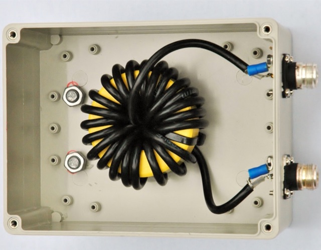 Choking balun for lower HF and MF bands. (1.8MHz - 10MHz). Requiring a choking balun to isolate the potential RF pick up on the coax cable as it runs past equipment such as computer within the radio room at lower HF and MF frequencies a simple method of winding RG58 coax onto a Powdered Iron Toroid Core was constructed.
 -
 This project outlines a simple, cost-effective 40m band HF dipole antenna design, ideal for beginners. Constructed with insulated copper wire and a 1:1 balun, it offers a 50-ohm impedance, suitable for both 40m and 15m bands due to the harmonic relationship. Calculations account for a K factor, ensuring optimal length and performance. Antenna modeling with 4NEC2 confirms practical access to both bands, though real-world results may vary. Lightweight materials and straightforward assembly make it an accessible and versatile amateur radio solution.