Search results
Query: vswr meters
Links: 17 | Categories: 0
-
 Demonstrates the construction of **magnetic loop antennas**, detailing both multi-turn and single-turn designs. It covers a 30-inch diameter multi-turn loop for 80 meters, based on a February 1996 QST article, and an octagon single-turn loop made from 15mm copper tube with a 4.8-meter circumference, operating from 7 MHz to 14 MHz. The document also presents a smaller 800mm diameter loop for 14 MHz to 28 MHz, emphasizing the importance of high-voltage tuning capacitors. Covers the design and construction of custom **butterfly capacitors** and piston capacitors, including a split stator capacitor with 140 pF capacitance and a 6000 Volt rating, and a butterfly capacitor with 5-65 pF and 7200 Volt rating. It explains why butterfly capacitors are preferred over split stator types for high power applications due to lower losses and direct series connection of rotors, reducing resistive losses from wiper contacts. Material recommendations include clear PVC for plates and brass or stainless steel for non-magnetic hardware. Addresses practical considerations such as feeding the loop with a shielded 1/5 Faraday loop made from RG213 or RG8 coax, achieving VSWR 1.1 across bands, and optimizing its placement 180° from the capacitor. It also discusses mechanical joint resistance, dissimilar metal oxidation prevention using Vaseline, and a simple method for determining radiation angle with a TL-light tube. The guide includes diagrams for rotor, stator, and end plate construction.
 -
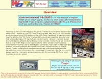 The "EZ-Tuner" is a homebrew automatic legal-limit antenna tuner that covers all amateur HF bands from 160-10 meters. Using a T-network design and controlled by a BASIC Stamp BS2sx microcontroller, the EZ-Tuner will match at least a 16:1 VSWR for either unbalanced or balanced transmission lines.
 -
 This technical note explores the application of **Moxon rectangle** antennas for WARC bands, specifically 17 and 12 meters, as compact directional alternatives to standard Yagis. It details three design approaches: a dual-band Moxon using open-sleeve coupling, a Moxon-Yagi combination, and a simplified 1.5 Moxon rectangle. The document provides specific dimensions in feet for aluminum tubing elements (0.75" and 0.5" diameter) for each configuration, along with projected free-space gain, front-to-back ratio, and feedpoint impedance (R+/-jX Ohms) across the respective band segments. Performance tables illustrate gain (dBi), front-to-back ratio (dB), and 50-Ohm VSWR for each design. The dual-band Moxon, despite its compact 7-foot boom, is not recommended due to extreme sensitivity to construction variations, leading to rapidly changing performance characteristics. The Moxon-Yagi combination, featuring a 17-meter Moxon and a 12-meter director-driver Yagi, is presented as a more practical and adjustable solution, offering stable performance with a 10-foot boom. NEC model descriptions are included for simulation in programs like EZNEC, NEC-Win Plus, AO, or NEC4WIN.
 -
 This resource presents a technical guide detailing antenna measurement theory, focusing on the fundamental electromagnetic principles governing antenna operation and characterization. It delineates the three primary spatial regions surrounding an antenna: the reactive field (0 < r < lambda/2pi), the radiating near-field (lambda/2pi < r < 2D2/lambda), and the radiating far-field (r > **2D2/lambda**). The guide defines key antenna parameters, including polarization, input impedance, VSWR, directivity, gain, efficiency, Effective Isotropically Radiated Power (EIRP), antenna noise temperature, and the G/T parameter. Radiation patterns are discussed, with examples of both rectangular and polar forms, emphasizing the determination of patterns in the far-field region for constant radial distance and frequency, typically characterized by a main beam with **3 dB** beamwidth and sidelobes. The document further elaborates on the mathematical definitions of these parameters, such as the Poynting vector (E x H*) for electromagnetic waves and the relationship between antenna gain and directivity. It also introduces related terms like mixers, which are critical components in antenna measurement instrumentation for frequency conversion (fIF = fRF +/-nfLO). The theoretical framework provided supports the scientific analysis of antenna performance, applicable to various antenna types and operational frequencies. DXZone Focus: Technical Guide | Electromagnetic Theory | Far-Field Region | G/T Parameter
 -
 This resource details the computer-optimized design of the _ZS6BKW_ multiband dipole, an evolution of the classic _G5RV_ antenna. It begins by referencing the original 1958 RSGB Bulletin article by Louis Varney G5RV, explaining the operational principles of the G5RV's flat-top and open-wire feedline on 20m and 40m, noting its impedance transformation characteristics for valve amplifiers of that era. The article then transitions to the rationale for optimizing the design for contemporary solid-state transceivers requiring a 50 Ohm match. The core of the project involves using computer modeling to determine optimal lengths for the flat-top and matching section, aiming for a VSWR of less than 2:1 on multiple HF bands. It discusses the process of calculating feedpoint impedance based on antenna length and frequency, referencing professional literature from Professor R.W.P. King at Harvard University. The analysis also considers the characteristic impedance (Z(O)) of the open-wire line, identifying a broad peak of adequate values between 275 and 400 Ohms. Specific design parameters for the improved ZS6BKW are presented, including a shorter flat-top and a longer matching section compared to the original G5RV, with a velocity factor of 0.85 for the 300 Ohm tape. The article confirms acceptable matches on 7, 14, 18, 24, and 28 MHz bands when erected horizontally at 13m, and also discusses performance in an inverted-V configuration, noting frequency shifts. The author, Brian Austin ZS6BKW, emphasizes the antenna's suitability for modern 50 Ohm coaxial cable without a balun.
 -
 The K0RWU 75-meter mobile antenna design features a 7.5-foot overall length, incorporating a 2.5-foot loading coil wound with #20 enamel wire on a 1/2-inch fiberglass rod, subsequently covered with 1/2-inch shrink tubing to increase diameter to 3/4 inch. This configuration achieved resonance at 3965 kHz with a 5-foot stainless steel whip. The antenna integrates a matching transformer, identified by larger turns near the PL259 connector, and is constructed using a modified Radio Shack CB antenna base. Construction involves drilling and epoxying a 1/2-inch fiberglass rod into a PL259 connector, feeding #20 enamel wire through the rod, and winding 17 turns of #18 matching coil wire between the PL259 sleeve and the center feed point. The main loading coil fills the 2.5-foot rod section. The design allows the antenna to bend for garage clearance and emphasizes maintaining a 50-ohm feed impedance to prevent vehicle electrical damage. The author also discusses experiences with a Yaesu ATAS-100 motorized antenna and a 10-meter antenna project, noting issues with auto couplers and the ATAS-100's performance on 17 meters. Future modifications considered include adding a small servo for band spreading and increasing the fiberglass rod length for a 3-foot loading coil to improve bandwidth. The antenna's sharp tuning, between 3960 kHz and 3970 kHz, necessitates careful adjustment of coil turns for optimal VSWR.
 -
 The document details the construction of a compact, two-element Quad antenna specifically designed for the 10, 12, and 15-meter HF bands, featuring a single feedline for all three bands. It provides specific dimensions for the driven element and reflector loops, along with boom length and spacing, emphasizing a **0.12 wavelength** spacing between elements. The design incorporates a gamma match for impedance transformation and uses PVC tubing for spreaders, aiming for a lightweight yet robust structure suitable for portable or restricted-space operations. Performance measurements indicate a forward gain of approximately **6 dBd** on 10 meters and a front-to-back ratio of _20 dB_ on 15 meters, demonstrating effective directivity and signal rejection. The antenna exhibits a VSWR below 1.5:1 across the target bands, achieved through careful tuning of the gamma match. This compact Quad offers a viable directional solution for HF DXing and contesting, particularly where full-size Yagis are impractical.
 -
 A 5/8 wavelength mobile whip antenna for 2 meters can be constructed from a 5-foot CB helical whip, requiring the removal of original wire and installation of a new radiating element made from coax braid. The design incorporates an 8-turn loading coil with 5mm spacing, fabricated from the original whip wire, and utilizes approximately 1400mm of RG-58 coax braid for the radiating element to enhance flexibility and bandwidth. Final whip length is approximately **1350mm** from base to braid end, with tuning adjustments made by trimming the braid. Dual-wall 12mm heat shrink, such as _Jaycar WH5643_, is recommended for weatherproofing and stabilization, costing around $4.50 per 1200mm length. Achieving a 1.1:1 VSWR may not be feasible; a 1.5:1 VSWR is considered acceptable. Optimal mobile mounting is centered on the vehicle roof to minimize radiation pattern variations.
 -
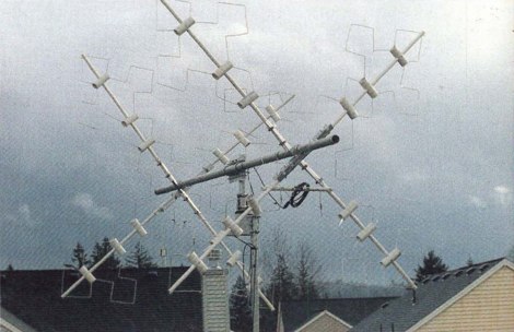 Presents the construction of a 10-meter Fractal Quad Yagi (FQY) antenna, detailing the design principles and practical build steps. The article highlights the antenna's compact size, with elements measuring just over 4 feet per side, making it suitable for easy erection and rotation with a TV rotator. It claims an impedance close to 50 ohms, allowing direct feed with 50-ohm coax, and specifies a 3 dBd gain with a front-to-back ratio exceeding 25 dB. Bandwidth is reported at 500 kHz for less than 2:1 VSWR. The resource includes a segment chart (Fig. 1) illustrating the precise lengths for each wire segment of the driven element and reflector, noting adjustments for different wire diameters. Construction utilizes readily available materials such as #9 aluminum ground wire and plastic water pipe for spreaders. The author, _KF7BS_, describes fabricating the framework, bending the fractal elements, and mounting them, including modifications like adding a small stub for reflector tuning. A materials list is provided, detailing items like 40-ft rolls of #9 Radio Shack aluminum ground wire and 1/2-inch plastic water pipe. Scaling equations for the driven element are discussed for different frequencies, such as designing for the CW band. The article references _Chip Cohen NIIRV_'s_ original _Fractenna_ website as the inspiration for the design.
 -
 A fractional bandwidth of up to 30:1 characterizes spiral antennas, making them highly effective across a very wide frequency range, often from 1 GHz to 30 GHz. The resource details two primary types: the **Log-Periodic Spiral Antenna** and the **Archimedean Spiral Antenna**, defining each with specific polar functions and illustrating their planar configurations. It explains that spiral antennas are typically circularly polarized, with a Half-Power Beamwidth (HPBW) of approximately 70-90 degrees, and a peak radiation direction perpendicular to the spiral plane. The content elaborates on critical design parameters affecting radiation, including the total length (outer radius) for lowest frequency, the flare rate ('a' constant) for optimal radiation versus capacitive behavior, the feed structure (often an infinite balun) for high-frequency operation, and the number of turns (typically 1.5 to 3 turns). It also discusses the theoretical impedance of 188 Ohms for Log-Periodic spirals, derived from Babinet's Principle, noting actual impedances are often 100-150 Ohms. The article presents a simple construction method for an Archimedean spiral, demonstrating VSWR and efficiency measurements. Measurements from a constructed spiral antenna show a VSWR that is fairly constant across the band, albeit with a mismatch loss of about 3 dB. The antenna efficiency remains around -5 dB (31.6%) across its operating range, indicating a decent wideband radiator despite opportunities for optimization.
 -
 G/T (Gain-to-Noise Temperature) is a critical figure of merit for evaluating the receive performance of VHF/UHF antennas, particularly for weak-signal work like EME (Earth-Moon-Earth) or meteor scatter. This resource presents extensive simulation data for numerous 2-meter and 6-meter Yagi antenna designs, originally compiled by _VE7BQH_ (Lance Johnson). The lists, updated as of October 2017, include various antenna models from designers such as _DK7ZB_, G0KSC, and K1FO, providing key performance parameters. Each entry details the antenna's G/T value, gain, front-to-back ratio, beamwidth, and VSWR at specific frequencies like 144.1 MHz or 145.0 MHz. The data facilitates comparison of different Yagi configurations, including those with folded dipoles and varying intrinsic impedances, aiding radio amateurs in selecting optimal antennas for their specific operational needs on the 2-meter and 6-meter bands.
 -
 Presents an interactive online **Moxon antenna designer** tool, enabling radio amateurs to configure and analyze lightweight Moxon antennas for HF and VHF bands. Users can specify design frequency, element lengths, wire diameter, insulation, and support height. The tool visualizes the antenna in interactive 3D graphics and generates comprehensive performance charts, including azimuth, elevation, 3D, and polarization radiation patterns, VSWR charts, antenna current diagrams, and Smith charts. It also allows selection of various ground types (e.g., very poor soil, salt water, free space) to model environmental effects on antenna performance. The designer provides insights into how physical dimensions and ground conditions influence key antenna parameters like forward gain, front-to-back ratio, and feed-point impedance, which is typically close to 50 ohms. It also includes a feature to model the effect of coaxial cable losses on **VSWR** at the transmitter end, distinguishing it from the feed-point VSWR. This helps operators understand the actual radiated power efficiency versus the apparent match at the transceiver, offering a practical perspective on antenna system performance in portable operations.
 -
 This article details a ham radio operator’s experience setting up HF antennas in an antenna-restricted community. Initially using an AEA Isoloop magnetic loop for QRP PSK, the author later built an attic antenna system, including dipoles for multiple HF bands and a slinky dipole for 40 meters. The setup allowed for operation on six bands with acceptable VSWR. Despite space constraints and some compromises, performance was effective. The article highlights practical strategies, emphasizing experimentation and antenna modeling for optimizing performance in limited-space environments. A valuable guide for ham radio operators facing similar restrictions.
 -
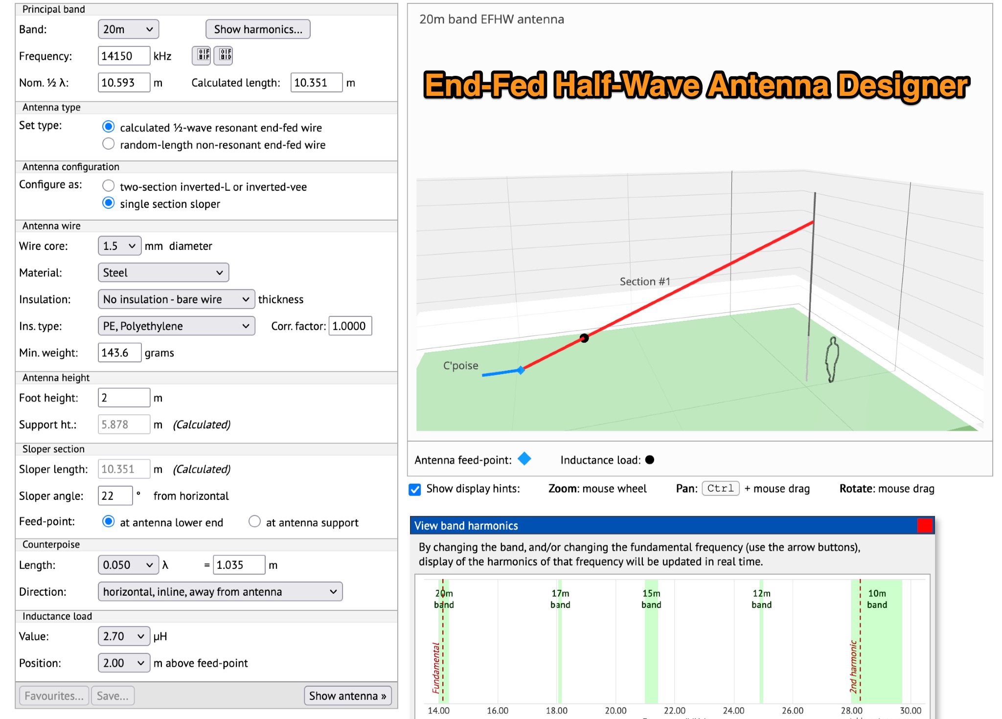 This page provides guidance on designing an End-Fed Half-Wave (EFHW) or Random-Length antenna for amateur HF bands, such as 80 or 40 meters. The content explains how to optimize the antenna for multi-band use and match it to a 50-ohm system using an unun. Hams can generate radiation patterns, VSWR charts, and antenna current diagrams for their customized antenna designs. Understanding how antenna dimensions affect performance is essential for successful field operations. The page caters to ham radio operators looking to build efficient and effective HF antennas for their stations.
 -
 This page provides information on how to design an Off-Center-Fed Dipole (OCFD) antenna, suitable for amateur HF bands like 80 meters or 40 meters. The antenna design allows for VSWR minima on multiple bands, making it a good choice for multi-band use. Learn how to create an OCFD antenna in either flat-top or inverted-Vee form using a single support. The page also offers tools to generate radiation patterns, VSWR charts, and antenna current diagrams for your specific antenna design, helping hams understand performance factors. Ideal for ham radio operators looking to build their own effective antennas.
 -
 The article explores the concepts of return loss, VSWR, and S11 within the context of microwave engineering, highlighting the confusion arising from their definitions. It clarifies that these parameters, while seemingly distinct, fundamentally describe the same phenomenon related to wave reflection and transmission in microwave circuits. The discussion emphasizes the historical context and mathematical relationships among these terms, revealing that their interpretation can vary significantly across different engineering disciplines. Ultimately, it advocates for a pragmatic approach to using these parameters based on familiarity rather than strict definitions.
 -
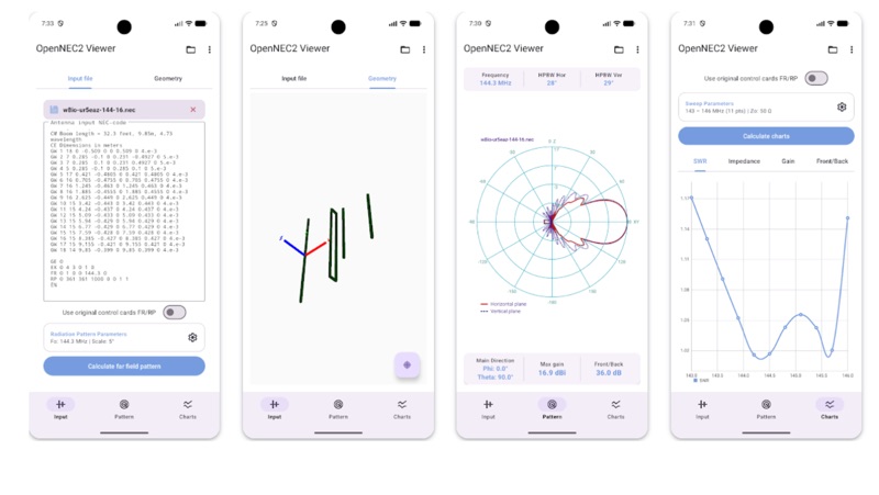 The Open NEC2 Viewer for Android provides a mobile platform for **NEC2** antenna modeling, enabling users to visualize and analyze antenna designs directly on their devices. It integrates the robust NEC2 computational library, leveraging the Method of Moments for full-wave electromagnetic analysis, and utilizes the Google Filament renderer for interactive 3D visualization of antenna structures, segmentation, and wireframes. The application facilitates the calculation of geometric parameters and antenna characteristics across specified frequency ranges. Key functionalities include parametric analysis, offering real-time computation of **radiation patterns** (RP), antenna gain, Voltage Standing Wave Ratio (VSWR), and input impedance. Users can configure flexible calculation settings to control scan step, frequency range, and various control cards, allowing for detailed electromagnetic analysis tailored to specific design requirements. Designed for radio engineers, antenna developers, radio amateurs, and students, the app is distributed as open-source software under the GNU General Public License v3.0. It provides a portable and accessible tool for electromagnetic modeling, making advanced antenna analysis capabilities available on Android devices.