Search results
Query: pdf
Links: 519 | Categories: 0
-
 Presents the design and construction of a folding 5-element Yagi antenna specifically engineered for 144 MHz portable operation, particularly for VHF contest Rover categories. It details element dimensions, boom construction using ¾-inch pine, and a folding mechanism that reduces the 52-inch boom to 26 inches for transport. The document provides a table with precise element distances and lengths, including a 2.4 mm length correction for solid parasitic elements, and specifies the use of 3/16-inch solid aluminum for parasitic elements and brass tubing for the driven element. It also covers the bent dipole driven element design for impedance matching, balun implementation with Type 31 ferrite beads for common mode current suppression, and weatherproofing for the feed point. The resource includes predicted performance data from 4NEC2 modeling, showing SWR and return loss characteristics, as well as gain and front-to-back ratios at various frequencies across the 2-meter band. It reports a measured SWR of 1.2:1 at 144.2 MHz and 1.5:1 at 147 MHz, corrected for 25 feet of RG-8/M coaxial cable loss. The design offers approximately 1.5 dB more gain than a previous 4-element design, maintaining a decent SWR up to 147 MHz, and was successfully deployed in a winning June 2016 ARRL VHF Contest Rover entry.
 -
 This article examines how geomagnetic activity influences 160-meter radio propagation. K9LA analyzes observations of enhanced signals preceding K-index increases. Modeling shows that as ionospheric electric fields rise from 0 to 75 mV/meter during early geomagnetic storms, they create an electron density valley above the E region, enabling signal "ducting" between the E and F regions. This effect vanishes at higher field strengths (100 mV/meter). The phenomenon may explain both exceptional 160m openings preceding 6m propagation and possibly Marconi's contested 1901 transatlantic reception, which occurred during a small geomagnetic disturbance.
 -
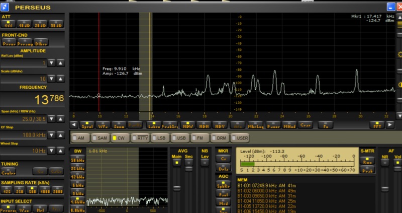 Investigates the performance characteristics of the _AAA-1_ active loop antenna across Very Low Frequency (VLF) and Low Frequency (LF) bands. It details the antenna's frequency response, explaining how a small loop with a low input resistance trans-impedance amplifier maintains a flat frequency response to electromagnetic field intensity E. The document illustrates current source and Thevenen equivalent circuit models for small loops, emphasizing the transition between these models based on frequency and load impedance. Measurement setups for both high frequency and VLF/LF responses are presented with diagrams, including methods for simulating current and voltage sources. The analysis includes normalized plots of the _AAA-1_'s frequency response for three distinct loop inductances, derived from measurements using a _Perseus SDR_ at 1 kHz bandwidth. It provides calculations for the noise floor at VLF/LF frequencies, comparing ambient noise levels with the antenna's internal noise floor. The resource also documents practical reception experiments in a semi-urban environment, showcasing successful reception of time transmitters like _MSF_ at 60 KHz and _SAQ_ at 17.2 KHz, along with various navy digital transmissions and Russian Alfa beacons.
 -
 A 5/8-wavelength vertical antenna for 2-meter FM operation is detailed, focusing on eliminating loading coils by utilizing a series inductor to cancel capacitive reactance at the feed point, thereby presenting a 50-ohm impedance match. The design illustrates three basic configurations, including a method employing a short-circuited coaxial stub for inductance, as implemented by K4LPQ. An alternative design is presented where the center conductor of the stub is extended one-quarter wavelength, creating a signal-frequency short and allowing for an insulated wire stub to develop the required series inductance. The article provides electrical theory and mechanical considerations for building the antenna, emphasizing the adjustment of stub length for proper impedance matching. This technical documentation is intended for amateur radio operators interested in homebrewing VHF antennas, offering practical insights into impedance matching techniques for vertical radiators.
 -
 Official English Brochure by ICOM of the IC-7760 HF and 50 MHz 200W Power output, transceiver. PDF File
 -
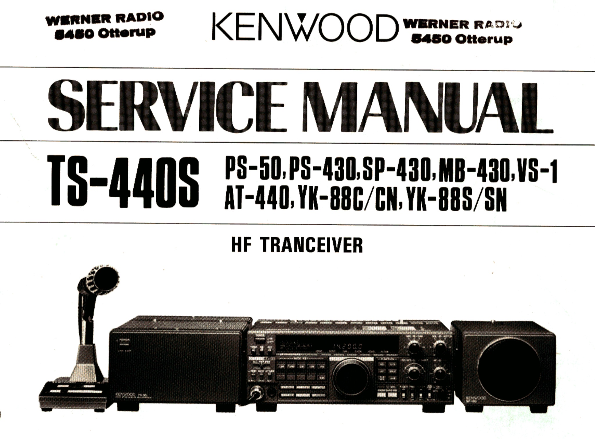 Kenwood TS-440S service manual PDF File, English version
 -
 Demonstrates a specific impedance matching technique for resistive loads ranging from 22.2 to 45 ohms, connecting them to a 50-ohm transmission line. The method employs series sections of 50-ohm and 75-ohm coaxial cables, with graphical data illustrating the required cable lengths (L1 and L2) in wavelengths for a perfect match. This approach is particularly useful for feeding **vertical** and **Yagi antennas**. The resource provides a practical example of matching a 25-ohm Yagi antenna at 50.150 MHz, specifying the use of RG-58C/U (50 ohms) and RG-59B/U (75 ohms) cables, both with a 66% velocity factor. It calculates the precise physical lengths in centimeters and inches for the required cable sections. Additionally, the document briefly discusses integrating a balun at the load end, suggesting methods such as coiling a cable section or utilizing ferrite beads to create a W2DU-type balun. The presented methodology offers a clear, data-driven solution for common antenna impedance challenges.
 -
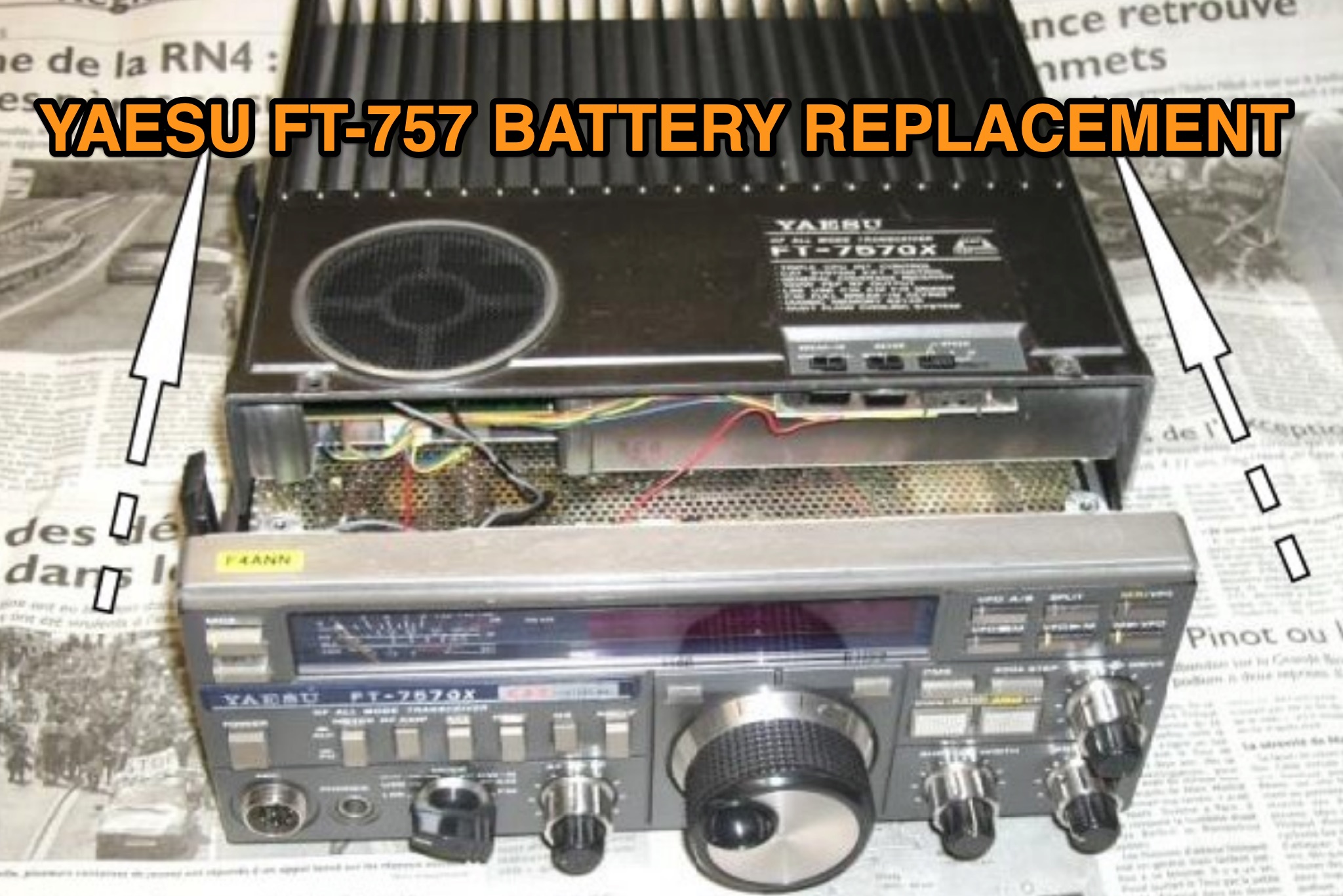 This guide by F4ANN (2014) explains replacing the backup battery in a YAESU FT-757 GX when stored frequencies reset on power-up. The original CR-1/3N lithium cell (3V, 160 mA) can be substituted with a CR2032 (170 mA), which is cheaper, widely available, and easier to replace. The process involves opening the transceiver, carefully desoldering the old battery from the PCB, and wiring in a holder for the CR2032. Extra care is required with screws, connectors, and soldering. The author also replaced backlights and serviced the cooling fan. Future battery replacements are simplified to four screws.
 -
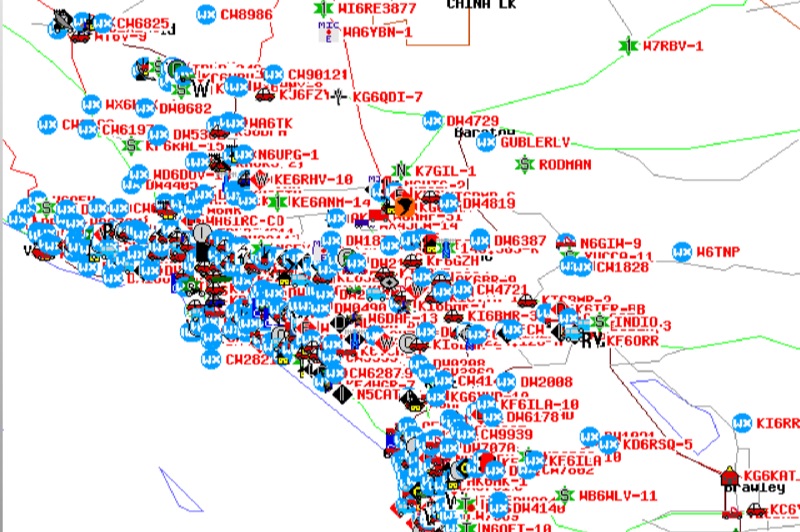 Demonstrates the Automatic Packet Reporting System (APRS) as a radio-based system for real-time tactical data exchange, leveraging the internet for messages, alerts, and bulletins to enhance situational awareness. It explains how APRS displays data on a map, integrating objects with GPS coordinates, weather stations, and alerts, clarifying its primary function as vehicle tracking despite broader capabilities. The document traces APRS development from the late 1980s by Bob Bruninga, WB6APR, through its evolution from Connectionless Emergency Traffic System (CETS) to Automatic Position Reporting System, and finally to Automatic Packet Reporting System with widespread GPS availability. Specific functionalities covered include real-time position and status reporting, message and bulletin exchange, weather data, DF bearings, RF connectivity plots, and local object display. Newer features like Global Email, CQSRVR, APRStt (APRS touchtone) for DTMF-based position reporting on frequencies like 146.58 MHz, and AVRS (Automatic Voice Relay System) for callsign-to-callsign linking via Echolink or IRLP, particularly with transceivers like the D710, are detailed. The resource also mentions AI-FI (APRS WIFI) for laptop integration and the use of the AX.25 protocol on 144.390 MHz in North America. It further describes the role of digipeaters and Internet Gateway stations (IGates) in transporting packets and connecting the on-air APRS network to the APRS Internet System (APRS-IS). The document explains APRS as a random ALOHA network, emphasizing channel loading considerations.
 -
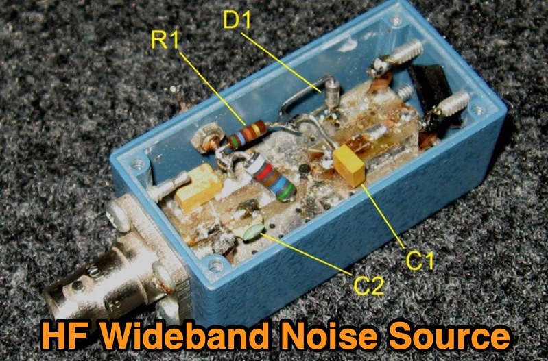 Details the construction of a **wideband noise source** for HF filter alignment, specifically targeting transceivers such as the Elecraft K2. The design modifies a Down East Microwave (DEMI) MMIC amplifier board, part number MMICPCB, by integrating a 1N4735A zener diode, 560-ohm resistors, and 4.7 nF, 10 nF, and 22 µF capacitors. This modification enables the board, originally configured for a MAR-6 MMIC (with MAR-1 as an alternative), to generate noise suitable for procedures like the K2's "CAL FIL" function. The resource provides a **schematic** and a comprehensive bill of materials, including specific component values for replication. It outlines the practical steps involved, such as removing the input connector and integrating the new components into the existing MMIC amplifier board layout. The output is optimized for wideband HF applications, ensuring compatibility with various filter alignment tasks. This project focuses on practical implementation, demonstrating how to repurpose readily available components for a critical test instrument. It offers a cost-effective alternative to commercial noise sources, leveraging existing amateur radio hardware for enhanced station maintenance and performance.
 -
 AA9PW offers free practice exams for all three US license classes plus international licenses like Canadian and Australian. The site generates random tests from the current question pools, simulating the actual exam experience. You can choose between online exams or printable PDF versions for offline study. The site maintains a simple, no-frills interface that loads quickly even on slow connections. Practice tests provide immediate feedback with score reports highlighting areas needing improvement.
 -
 The Spartan Sprint Special 40m CW Transceiver, originally documented in 2002 and reproduced in 2019, details a **QRP** direct conversion rig designed for portable operation. This project evolved from an experimental CMOS digital IC receiver, which proved too noisy for weak signals, into a dedicated 40-meter CW transceiver. The author, VE3SMA, aimed for reduced size, lower weight, and decreased receive current drain compared to earlier iterations, drawing on his extensive contesting experience and even his time operating million-watt transmitters at Radio Canada International. This compact transceiver delivers approximately 200 mW output, VFO-tunable over 15 kHz within the 40m band, and weighs a mere 73 grams (0.16 lb) including its balsa wood case. It features fast semi-break-in and sidetone, with a receive current draw of about 14 mA (no signal) and transmit current draw around 125 mA key down. The design incorporates various construction techniques, including knife-cut surface mount boards and through-hole components, often salvaged from junked cordless phones and cellphones. Despite its direct conversion architecture, which offers usable but not superheterodyne-level selectivity, the rig proved effective, achieving a fourth-place finish in a June 2001 Spartan Sprint contest when paired with a 26-foot vertical antenna. The article provides comprehensive circuit details, including an unconventional VFO using a high-speed CMOS inverter chip and a balanced mixer utilizing a 74HC4053.
 -
 A common mode choke/balun, essential for mitigating common mode current on antenna feedlines, is detailed in this construction and measurement guide. It utilizes eight Fair-Rite #2643167851 Mix 43 ferrites housed within a Hammond 1598JSGYPBK plastic case, with RG-8X coax cable forming the windings. The document references design principles from Ian White, GM3SEK's article on cost-effective ferrite chokes. Specific construction details include the layout of three coils to minimize inter-coil coupling and methods for securing the ferrites with foam tape. The resource presents comprehensive measured data, including isolation impedance (magnitude, real, and imaginary components), Q factor, inductance, and phase angle across various frequencies. It also covers the choke/balun's coax frequency response and return loss characteristics. Techniques for measuring choking impedance are thoroughly explained, focusing on S21 transmission measurements with a Vector Network Analyzer (VNA) and testing ferrite beads in both S11 and S21 modes. The guide describes a practical setup using an aluminum sheet or baking foil for measurements and outlines the calculation of series impedance from attenuation in a 50-ohm system. Additionally, it details a method for determining the balun's equivalent L and C around resonance by adding a parallel capacitor.
 -
 Understanding how radio frequency interference (RFI) is coupled into equipment and subsequently detected is crucial for amateur radio operators. This guide delves into the fundamental mechanisms of RFI, particularly focusing on detection at semiconductor junctions and the unintended antenna action of system wiring. It explains that most RFI detection follows a square law, meaning a 6 dB reduction in RF signal can result in a 12 dB drop in detected audio, offering a practical approach to mitigation. The resource also clarifies the concept of common mode versus differential mode signals, detailing how cable imperfections can convert common mode antenna current into differential signals. It addresses the critical "Pin 1 Problem" in audio interfacing, a common design flaw where cable shields connect to the circuit board instead of the shielding enclosure, leading to significant RFI issues. Practical solutions, such as proper shielding, using twisted-pair cables, and strategic bonding of equipment, are discussed to effectively reduce or eliminate RFI. The guide emphasizes the importance of proper filtering and the often-misunderstood concept of "ground" in electrical systems, distinguishing between earth ground, equipment ground, and circuit common. It provides insights into minimizing loop area in wiring to reduce inductively coupled noise and antenna action, drawing on the author's extensive engineering background and ham radio experience.
 -
 The 4m Slim Jim antenna project provides a construction guide for a low-cost, high-performance aerial designed specifically for the 70 MHz FM band. This design achieves a 1:1 SWR across the 4m FM band with straightforward adjustment of the feed point, utilizing RG-58 coax. Its low angle of radiation contributes to effective signal propagation. Construction involves using plastic knitting needles as spreaders and a telescopic fishing pole for support, with components secured using two-part epoxy. Annealed bare single-core copper wire forms the radiating element. The setup process includes raising the antenna at least 3 meters above ground for tuning, adjusting the RG-58 feed point for optimal SWR, and then soldering connections. Waterproofing is achieved with yacht varnish. The design emphasizes low wind resistance for durability, making it suitable for exposed outdoor installations. A PDF construction diagram is available to supplement the written instructions.
 -
 VE2AZX's 2013 Radio Talk presentation details the technical aspects of baluns, including reasons for their use, various types, and methods for performance verification using an SWR analyzer. The document specifically examines 1:1 voltage baluns and 4:1 voltage baluns, outlining their winding configurations and typical impedance transformations. It presents empirical SWR measurements for W2AU 1:1 baluns and Unadilla 4:1 baluns, tested with both 50-ohm and 200-ohm resistive loads across the HF spectrum. The presentation further explores the measurement of ferrite impedance and their application in mitigating common-mode currents on feeders and household conductors. Key concepts addressed include balanced-to-unbalanced transformation, ensuring feeder independence from the antenna, and reducing unwanted feeder radiation. The content emphasizes practical testing procedures to ensure optimal antenna system performance and minimize RF interference. Discussions also cover open-circuit tests with SWR analyzers and VNAs to assess winding inductance, distributed capacitance, and insulation quality. The presentation differentiates between voltage and current baluns, explaining how current baluns, particularly those utilizing ferrite cores, reduce outer shield currents without affecting internal coaxial cable currents, thereby preserving the antenna's intended radiation pattern.
 -
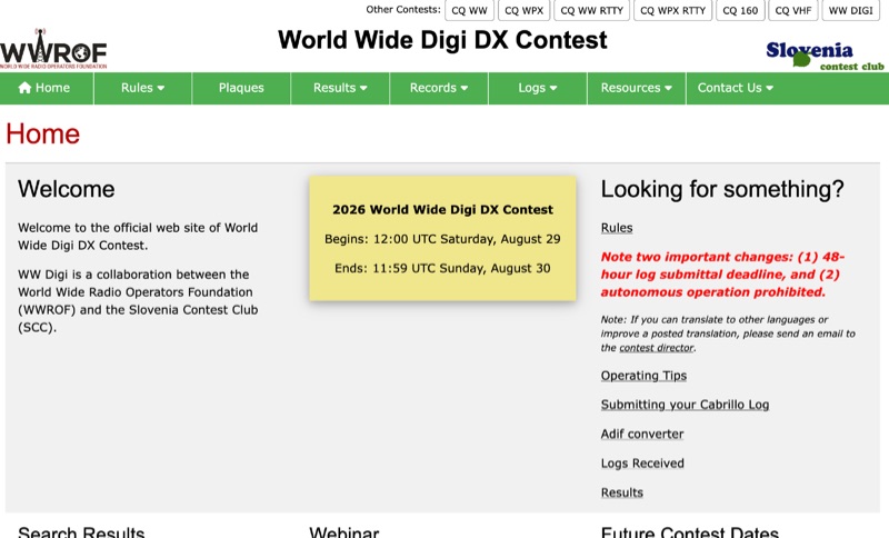 The **World Wide Digi DX Contest** website serves as the official hub for this annual digital DX event, a joint effort by the World Wide Radio Operators Foundation (WWROF) and the Slovenia Contest Club (SCC). It details critical operational changes, such as a strict 48-hour log submittal deadline and the prohibition of autonomous operation, ensuring fair play and adherence to contest guidelines. Participants can find comprehensive operating tips, instructions for submitting **Cabrillo logs**, and access to an ADIF converter to streamline their post-contest workflow. The resource clearly outlines future contest dates, consistently held on the last full weekend of August, with specific dates listed through 2029, including August 29-30, 2026, and August 28-29, 2027. Beyond the WW DIGI contest, the site also references other major contests like CQ WW, CQ WPX, and CQ 160, providing a broader context for digital and traditional contesting. A video recording and presentation PDF from the 2019 event are also available, offering insights into past operations.
 -
 Kenwood TS-520S English Operating Manual in PDF Format provided by Kenwood
 -
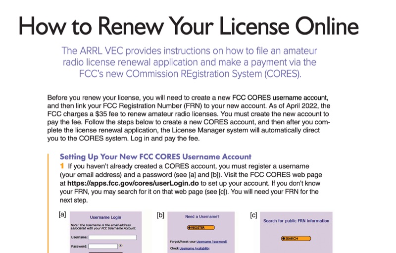 This resource provides a procedural guide for renewing an amateur radio license online through the FCC's COmmission REgistration System (CORES) and Universal Licensing System (ULS). It details the steps for creating a new FCC CORES username account, linking an FCC Registration Number (FRN) to the account, and managing FRN passwords. The document outlines the process for submitting a renewal application via the FCC ULS License Manager system, including payment of the **$35** renewal fee. Instructions cover license renewal eligibility within **90 days** before expiration and during the 2-year grace period post-expiration. The guide specifies the use of the FCC CORES web page at `https://apps.fcc.gov/cores/userLogin.do` for account setup and the FCC ULS License Manager system at `https://wireless2.fcc.gov/UlsEntry/licManager/login.jsp` for application submission. The process concludes with receiving an email from the FCC containing a link to the official license, valid for 30 days.