Search results
Query: 7 hz antenna
Links: 717 | Categories: 14
Categories
- Antennas > 40M > 40 meter Delta Loop Antennas
- Antennas > 40M > 40 meter Dipole Antennas
- Antennas > 40M > 40 meter Yagi Antennas
- Antennas > 6M > 6 meter Moxon Antennas
- Manufacturers > Antennas > VHF UHF Microwave > Microwave antennas
- Antennas > 20M
- Antennas > 23cm
- Antennas > 2M
- Antennas > 30M
- Antennas > 4M
- Antennas > 6M
- Antennas > Longwave
- Radio Equipment > HF Vertical Antenna > Maldol MFB-300
- Operating Modes > Microwave
-
 Guide to constructing an effective antenna for 50MHz. Inspired by a design from Martin DK7ZB, the article emphasizes the importance of precise measurements and quality materials. With a 2.20m boom and careful assembly, the antenna promises excellent performance, resilience, and cost-effectiveness, making it ideal for six meter band operations.
 -
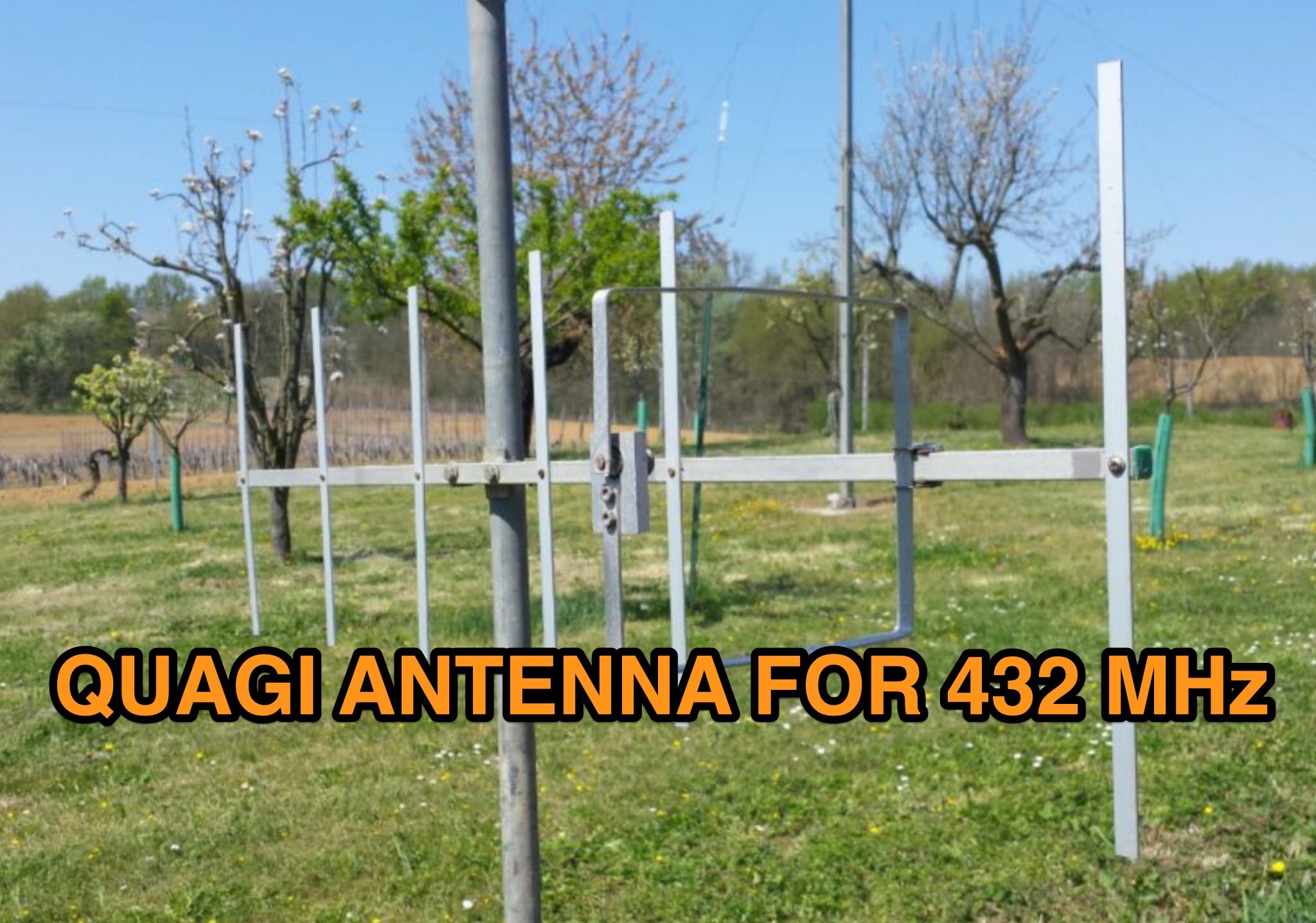 Antenna project for a home made quagi antenna for UHF Bands, 432 MHz. This projects is done using some aluminium bar rods and includes design and pictures of the project
 -
 This paper presents an 80 meter wire 3-element beam antenna in an inverted-V configuration, designed for limited-height towers. Using EZNEC modeling, the antenna features a central parasitic reflector and two switchable driven elements at each end, enabling NE/SW coverage without moving parts or networks. Element lengths are optimized for SSB (3.8 MHz) and CW (3.5 MHz) operation, with a 50 Ω feed and rope-supported boom. The design delivers high gain, effective takeoff angles, and excellent reception, confirmed in real-world DX contest operation. Its simplicity, reliability, and ease of construction make it ideal for operators seeking performance without complex matching systems.
 -
 This resource details the construction and performance of a compact broadband magnetic loop antenna designed for portable receiving applications with devices like the _ATS MiniRadio_. The antenna utilizes approximately 3 meters of 0.5–1 mm copper wire wound in two turns on a rhomboidal wooden frame, measuring 50 cm by 70 cm. It connects via a modified 9:1 unun, where the primary center tap is isolated from ground to improve common-mode noise rejection. The design provides untuned operation across a frequency range from the longwave band up to approximately 25 MHz. Performance characteristics include observable directivity for noise suppression and the ability to connect directly to a radio or via a 50 coaxial cable for remote operation. The article specifies the unun's 3:1 turns ratio and its SMA output for connectivity. The methodology focuses on practical construction and observed reception quality.
 -
 This paper by Leif Asbrink (SM 5 BSZ) presents a practical approach to designing very high gain Yagi antennas, focusing on the "brute force" optimization method. The method, described in a previous article, ensures convergence independent of initial guesses. The paper provides detailed tables of element lengths and positions for Yagi antennas optimized for 144.1 MHz with a 50-ohm feed point impedance, aiming for minimal losses and high accuracy in comparisons.
 -
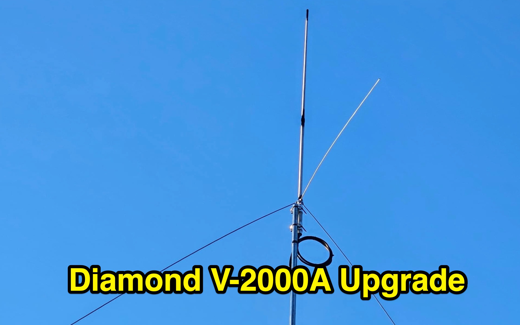 Learn how to enhance the performance of your Diamond V2000A antenna by optimizing the length of the radials. Discover a cost-effective method to create improved radials using simple materials like aluminum tubes and bolts. Explore the benefits of this modification for 6m band, unlocking triband capabilities and better SWR. Find out how a ham radio operator from Europe successfully upgraded their V2000 antenna and achieved impressive results. Save money by DIY-ing your radial enhancements instead of purchasing expensive replacements.
 -
 145 MHz is the target frequency for this 2-meter Skeleton Slot Yagi Stack antenna project. The design focuses on feeding two stacked Yagi antennas using a skeleton slot radiator, which is a unique approach for VHF enthusiasts. The project details the construction process, including the loop tapered matching section for impedance matching, ensuring optimal performance. The use of specific components like the EH789 element holder and MB456 main mast bracket is highlighted, providing clarity on the assembly process. The construction utilizes 20x20 box aluminum bar for durability and precision. Key dimensions, such as the element length (ER-ED4) and main boom spacing (MM123), are meticulously outlined. This attention to detail aids in replicating the antenna design accurately. The downloadable PDF offers comprehensive instructions, making it accessible for amateur radio operators interested in VHF antenna construction. This project is particularly beneficial for those looking to optimize their 2-meter band operations. The inclusion of a skeleton slot radiator and loop tapered matching section demonstrates advanced techniques in antenna design, catering to both intermediate and advanced builders.
 -
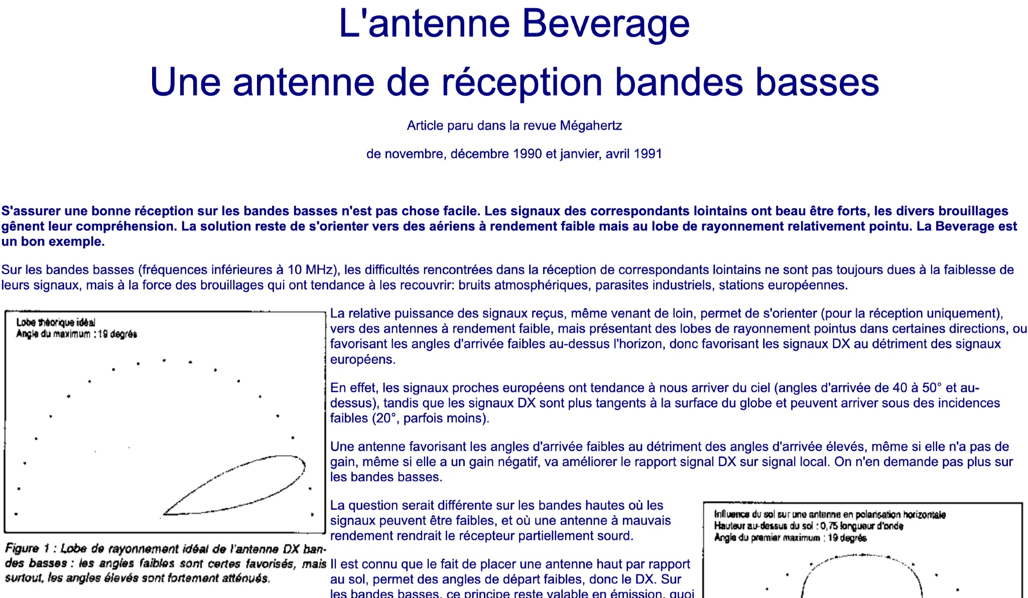 This article discusses the Beverage antenna, a reception antenna for low bands, originally published in the Megahertz magazine between November 1990 and April 1991. It explains the challenges faced in receiving signals on low bands due to interference and how the Beverage antenna's directional radiation pattern can help improve reception of distant stations. The article highlights the importance of choosing antennas with low efficiency but sharp radiation lobes for better DX signal reception. It also compares the reception characteristics of signals from European stations versus DX stations, emphasizing the benefits of antennas favoring low arrival angles for DX signals on low bands.
 -
 Early 20th-century transatlantic wireless communication efforts involved distinct technical approaches by Reginald Fessenden and Guglielmo Marconi. Marconi's systems, operational until approximately 1912, primarily utilized _spark technology_ for wireless telegraphy, facilitating Morse code communication between ships and across oceans. His Poldhu station in December 1901 radiated signals in the MF band around 850 kHz, later evolving to 272 kHz in October 1902, and eventually 45 kHz by late 1907 with increasingly larger antenna structures like the pyramidal monopole and capacitive top-loaded arrays. Fessenden, conversely, focused on _continuous wave transmission_ for wireless telephony, recognizing its necessity for speech. His transatlantic experiments in 1906 employed synchronous rotary-spark-gap transmitters and 420-foot umbrella top-loaded antennas at Brant Rock, MA, and Machrihanish, Scotland, tuned to approximately 80 kHz. Fessenden later utilized the _Alexanderson HF alternator_ at 75 kHz by late 1906 for pure CW transmission, integrating a carbon microphone for amplitude modulation. Receiver technology also differed, with Marconi initially relying on untuned coherer-type detectors, later developing the magnetic detector in 1902, while Fessenden's CW approach necessitated more advanced detection methods.
 -
 This study analyzes the antenna pattern of the Utah Amateur Radio Club's 146.760 MHz repeater following antenna relocation in 1997. Noting degraded transmission toward the north, a customized signal mapping system using a Yaesu FT-817, GPS, and software was developed to log real-time signal data. Calibration techniques extended the radio's signal range, enabling precise field measurements. The method allowed continuous signal strength monitoring while driving, revealing anomalies in coverage likely due to tower modifications. Findings helped assess and visualize the antenna’s actual radiation pattern and highlighted environmental impact on signal distribution.
 -
 SAT filters ensure effective full-duplex satellite QSOs by mitigating interference between 145 MHz uplink and 435 MHz downlink signals. Custom coaxial and SMD-based filters address transmitter harmonic interference and improve receiver isolation, achieving over 70 dB suppression in the undesired band. Designed for simplicity, these filters maintain optimal VSWR and are housed in shielded brass enclosures. Practical implementations with Yagi antennas demonstrate compatibility with SDR systems, enabling seamless communication even in challenging satellite conditions, such as low-elevation passes and DX pile-ups.
 -
 Demonstrates the construction of an active loop converter specifically designed for the Low Frequency (LF) bands, addressing common localized noise interference in LF reception. The design integrates a sharply tuned circuit and a tuned loop antenna, utilizing the loop as the sole tuned inductive element. By applying positive feedback, the converter significantly increases the loop's effective Q, achieving factors between 1000 and 2000, which sharpens tuning and reduces noise. The circuit employs an _NE602_ mixer stage, feeding its output to an HF receiver, with a crystal-locked local oscillator at 4 MHz. A 20-turn, 0.8-meter square loop antenna with 500 uH inductance is detailed, connected via 2 meters of figure 8 flex cable. The converter offers three selectable frequency bands: 195-490 kHz, 150-220 kHz (including the New Zealand amateur band), and 128-160 kHz (covering the European amateur band). Performance measurements indicate an effective 3dB bandwidth of approximately 100 to 200 hertz at 200 kHz. The article provides insights into component selection, including an _LF353_ op-amp and a trifilar wound transformer on a ferrite core. Sensitivity figures are presented, showing 7.5 uV of converted output per 1 uV/meter signal strength into a 50-ohm load, or 37.5 uV into an _FRG7_ receiver, highlighting its capability to extract weak signals from noise.
 -
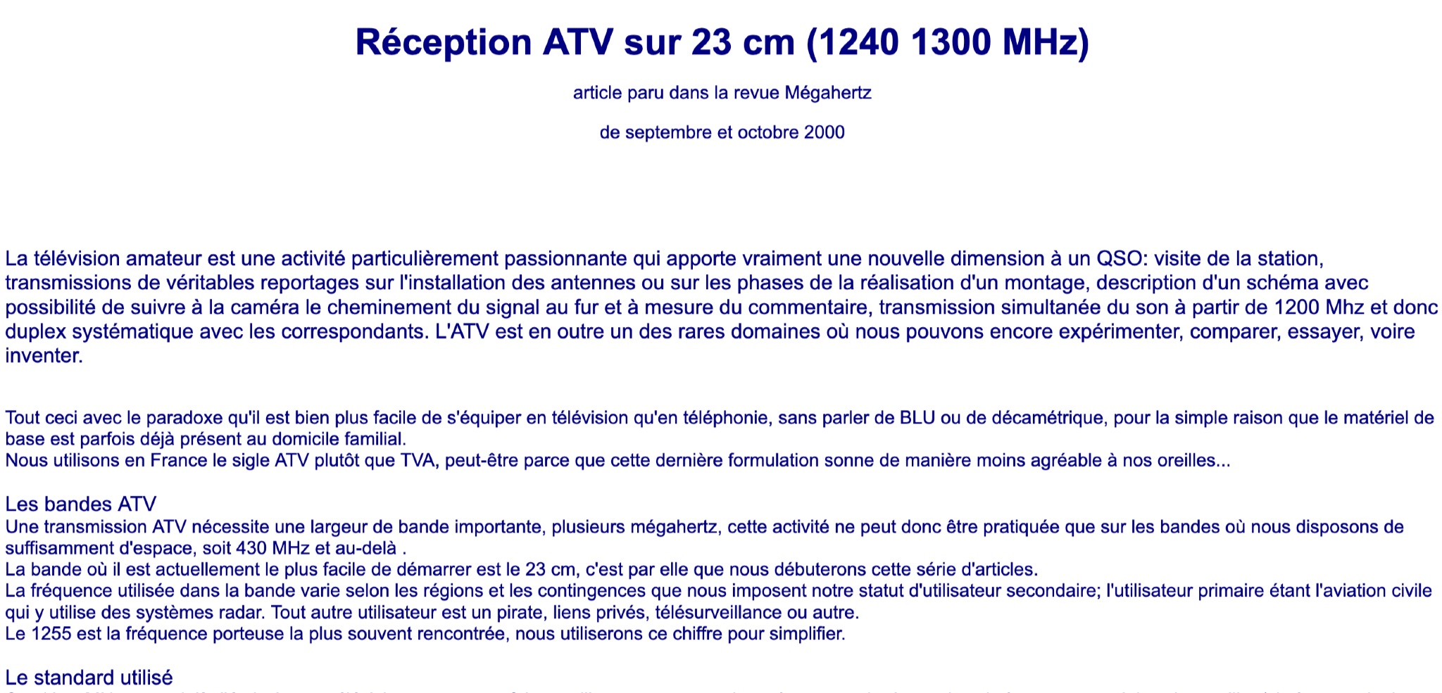 Learn about Amateur Television (ATV) on the 23 cm band (1240-1300 MHz) in this article from the September and October 2000 issue of Mégahertz magazine. Discover how ATV adds a new dimension to QSOs by allowing hams to visit stations, transmit real reports on antenna installations, follow signal paths on camera, and have simultaneous sound transmission. Explore the world of ATV experimentation, comparison, and innovation, made easier by existing equipment in many ham radio operators' homes. Find out about the ATV bands, bandwidth requirements, and the 23 cm band as a starting point for ATV activities.
 -
 The 4m Slim Jim antenna project provides a construction guide for a low-cost, high-performance aerial designed specifically for the 70 MHz FM band. This design achieves a 1:1 SWR across the 4m FM band with straightforward adjustment of the feed point, utilizing RG-58 coax. Its low angle of radiation contributes to effective signal propagation. Construction involves using plastic knitting needles as spreaders and a telescopic fishing pole for support, with components secured using two-part epoxy. Annealed bare single-core copper wire forms the radiating element. The setup process includes raising the antenna at least 3 meters above ground for tuning, adjusting the RG-58 feed point for optimal SWR, and then soldering connections. Waterproofing is achieved with yacht varnish. The design emphasizes low wind resistance for durability, making it suitable for exposed outdoor installations. A PDF construction diagram is available to supplement the written instructions.
 -
 This presentation explores the practice of QRP (low-power) amateur radio operation in outdoor settings. It guides operators to identify their specific objectives for portable operations, which inform equipment and antenna choices. The discussion covers considerations including portability, operating modes, power requirements, and weather resistance. Various antenna designs are examined, from vertical configurations to dipoles and end-fed options, with emphasis on deployment practicality in public spaces. The presentation concludes with practical advice on selecting operating locations, RF safety, and resources for equipment and community support for QRP enthusiasts.
 -
 The W6PQL 23cm Beacon Project describes a **1296 MHz** beacon designed for microwave propagation studies and equipment testing, capable of 30 watts output. It utilizes a PIC 16F628A microcontroller to generate CW and FSK keying for a crystal oscillator, followed by a series of frequency doublers and triplers to reach the target frequency. The final power amplification stage employs a Mitsubishi M57762 module, providing a robust 10-watt RF output. The design emphasizes stability and reliability for continuous operation, with the microcontroller code, written in assembly, provided for customization of the beacon's callsign and message. Originally located in CM97am and aimed at 140 true, the beacon used four 4-foot Yagis stacked vertically for a total ERP of 3kW. The article includes schematics, parts lists, and construction notes to guide builders, along with antenna pattern measurements. Although the beacon itself is no longer in service as of August 2010, the detailed documentation remains a valuable reference for amateur radio operators interested in building similar **microwave** projects or understanding beacon operation.
 -
 Operating an **Echolink** gateway on the 4-meter band presents unique opportunities for extending VHF communications, as demonstrated by the EI4FMG node. Situated at Fieldstown, Monasterboice, this gateway provides coverage across a significant portion of Ireland's east coast, leveraging a Tait TM8100 radio and an EI4JR Echolink interface logic. My own experience with similar setups confirms the importance of strategic site selection for maximizing reach, particularly with a 122-meter elevation above sea level. Access to the EI4FMG gateway, identified by node 57006, requires a **CTCSS** tone of 88.5 Hz, a standard practice for managing access and minimizing interference on shared frequencies. The system transmits with 15 watts of power and utilizes a Sigma CAT70 @5MAGL antenna, a configuration well-suited for regional VHF coverage. The gateway also features an auto-ID every 8 minutes, ensuring compliance and clear station identification. Users can interact with the gateway using various DTMF commands, allowing for connections to specific nodes, random repeater/link or conference nodes, and managing disconnections. These functionalities streamline the process of linking into the broader Echolink network, enabling local VHF operators to communicate globally through the internet backbone.