Search results
Query: power mic
Links: 117 | Categories: 0
-
 The _Sci.Electronics FAQ: Repair: RFI/EMI Info_ document, authored by Daniel 9V1ZV, provides a detailed analysis of computer-generated RFI/EMI, focusing on its impact on radio reception. It identifies common RFI sources such as CPU clock rates (e.g., 4.77 MHz to 80 MHz), video card oscillators (e.g., 14.316 MHz), and even keyboard microprocessors, all of which generate square-wave harmonics across HF and L-VHF regions. The resource outlines a systematic procedure for pinpointing RFI origins, including disconnecting peripherals and using a portable AM/SW receiver with a ferrite rod antenna to localize strong interference sources. The document categorizes RFI mitigation into shielding, filtering, and design problems, offering practical solutions for each. It recommends applying conductive sprays like _EMI-LAC_ or _EMV-LACK_ to plastic casings of radios, monitors, and CPUs to create effective Faraday cages, emphasizing proper grounding and avoiding short circuits. For filtering, the guide suggests using line filters, ferrite beads, and toroids on power and data lines, and small value capacitors (e.g., 0.01 uF for serial/parallel, 100 pF for video) to shunt RFI to ground. It also discusses the use of bandpass, high-pass, low-pass, and notch filters on the receiver front-end or antenna feed to combat specific in-band noise.
 -
 This online project guide details the construction of a homebrew boom microphone system. It details the assembly of a microphone shell from a 3/4" PVC pipe section and an end cap, requiring a drilled hole for a snug fit of the electret or condenser mic element. The internal wiring schematic specifies a **2.2 K** resistor and a **47 uF** polar capacitor for signal conditioning, with a circuit diagram provided for integration with IC-706 series transceivers. The guide outlines the use of CAT-5 cable for internal connections, incorporating strain relief at the rear of the mic shell, and an inline 3.5 mm jack to facilitate an external _PTT_ line, designed for a foot-mounted switch. Further construction involves fabricating a microphone shock mount from a 2-inch PVC connector, detailing the creation of four "fingers" and the insertion of screw-eyes for attaching elastic bands, which are twisted 180 degrees for tensioning and vibration isolation. A foam wind screen is also incorporated into the microphone assembly, secured with adhesive. The boom arm itself is repurposed from an articulated architect lamp, with the original lamp assembly converted into a **60 watt** resistive load for testing power sources. Microphone cabling is secured to the boom arm using wire ties, ensuring sufficient slack at hinge points to maintain articulation. The boom base is mounted to a bookshelf, requiring specific positioning to achieve proper microphone placement in front of the operator. Performance evaluation of the microphone system is conducted through on-air audio signal reports from other amateur radio operators. DXZone Focus: Online Project Guide | Boom Microphone Construction | Electret Mic Element | PTT Line
 -
 A synthesized 2.3 GHz Amateur Television (ATV) transmitter design, conceived by Ian G6TVJ, is presented, targeting broadcast-quality video performance on the 13cm band and extending up to 2.6 GHz. The core of the design utilizes a commercial Z-comm Voltage Controlled Oscillator (VCO) that tunes from 2.2-2.7 GHz, providing a +10 dBm output and simplifying RF alignment. This VCO's stability, originally intended for narrowband applications, readily accepts high-frequency video modulation, contributing to the transmitter's robust performance. The exciter stage, incorporating a Mini Circuits VNA 25 MMIC amplifier, boosts the signal to +16dBm, while a Plessey SP4982 prescaler divides the output frequency for the synthesizer. The synthesizer employs a Motorola MC145151 CMOS parallel IC, favored over the common Plessey SP5060 for its superior video modulation characteristics and ease of programming without microprocessors. This choice addresses issues like LF tilt and distorted field syncs often seen with SP5060 designs, particularly when operating through repeaters or over long distances. The MC145151 divides the signal further, enabling precise frequency stepping, with programming handled by EPROMs for channel selection and LED display. The loop filter network, critical for video integrity, was developed through experimentation to prevent the PLL from reacting to video modulation, ensuring a clean transmitted picture. The transmitter incorporates a Down East Microwave commercial power amplifier module, delivering approximately 1.6W output, driven by the exciter through a 3dB attenuator. Construction involves surface-mount SHF components on micro-strip lines etched onto double-sided fiberglass board, housed within a tinplate box. The design boasts no AC coupling in the video path, preserving low-frequency response, a common failing in other ATV transmitters. Performance tests with a 50Hz square wave revealed no LF distortion, and a calibrated "Pulse & Bar" signal showed a near 100% HF response, demonstrating its capability for high-quality ATV transmissions.
 -
 Amplifiers, filters, attenuators, mixers, PLL, switches and frequency dividers, signal generators, power detectors, transimpedance amplifiers, variable gain amplifiers and more
 -
 A keyed piezo beeper, connected to the microphone jack of a HT, appeared feasible as a ready-made MCW generator.
 -
 Maxdao: offer you 7/16, N coaxial connectors, jumper cables, feeder clamps and grouding kits, surge arresters & brackets, wall entries and microwave components used in base tower, power dividers, couplers
 -
 Naptech buys and sells quality test equipment from hp, tektronix, including spectrum analyzers & peripherals, oscilloscope, frequency counters timers, signal generators, multimeters & voltmeters, RF & power meters, microwave amplifiers
 -
 Examines Radio Frequency Systems (RFS), a manufacturer specializing in high-performance cable solutions for diverse communication infrastructures. The company, with over 120 years of heritage, focuses on designing and producing robust, long-life connectivity systems, including _low loss foam dielectric RF cable_ and _premium radiating cable_. RFS's product range supports critical applications in cellular networks, microwave antenna systems, and specialized installations within buildings and tunnels. The resource highlights RFS's commitment to innovation, addressing emerging industry standards like _FRMCS_ for railway communication and advanced fiber solutions for data centers. It also details the company's manufacturing capabilities in Hannover, Germany, emphasizing the quality and reliability associated with _Made in Germany_ products. The content covers various connectivity landscapes, from urban solutions for connected cities to private 5G credentials and future plans. Specific product categories include _fiber, power & hybrid cable_, and _low loss high power air dielectric RF cable_, showcasing their broad portfolio for complex RF environments.
 -
 A low cost, low power microwave transverter so that you can operate easily on 70cm band even with a HF or VHF transceiver
 -
 Manufacturer of precision equipment, Power meters Wattmeters
 -
 Traveling Wave Tubes , Conventional Traveling Wave Tubes, Microwave Power Modules manufacturer
 -
 Operating in the **microwave** spectrum, Response Microwave, Inc. specializes in the design and manufacturing of RF and microwave signal processing components and subsystems. The company's product line encompasses a wide array of offerings, including Connectivity Series components, rotary joints, phase shifters, cable assemblies, surge protectors, terminations, Hybridline/Couperline products, circulators/isolators, directional couplers, quadrature hybrids, attenuators, custom assemblies, filters/diplexers, DC blocks & bias tees, power dividers/combiners, laser diodes & drivers, high-frequency connectors, and precision test accessories. This extensive catalog supports various applications requiring precise signal manipulation and transmission at elevated frequencies. The resource provides access to a comprehensive product catalog and a dedicated connector catalog, detailing specifications for components like **high-frequency connectors** and test cables. While specific performance data or comparative analyses are not directly presented on the main page, the breadth of products indicates a focus on providing foundational building blocks for microwave systems. The company emphasizes customer service and aims to be a reliable source for RF/Microwave/Optics product requirements, serving a growing customer base with its specialized component offerings.
 -
 Sixty-meter repeaters typically use a 1 MHz frequency separation between input and output, while 2-meter repeaters commonly employ a **600 kHz** split and 70-centimeter repeaters use a **5 MHz** offset. This article details the fundamental technical principles of amateur voice repeaters, explaining how they extend VHF/UHF communication range by receiving on one frequency and simultaneously retransmitting on another. It covers essential components such as receivers, transmitters, filters, and antennas, often situated on elevated locations for optimal coverage. The resource delves into the critical challenge of _desensing_—where the repeater's strong transmit signal overpowers its own receiver—and the engineering solutions employed, including antenna separation and the use of high-Q cavity filters. It also explores various control and timing systems, from basic squelch activation to more sophisticated microcontroller-based boards that manage functions like voice identification, time-out timers, and fault protection. Different access methods are discussed, including open access, toneburst, CTCSS subtone, and DTMF, each offering distinct advantages for managing repeater usage and mitigating interference. Furthermore, the article examines repeater linking, both conventional RF methods and modern internet-based solutions, highlighting how linking expands coverage and promotes activity across multiple repeaters or bands. It introduces less common repeater types such as 'parrot' repeaters, which use a single frequency and digital voice recording, and linear translators, capable of relaying multiple signals and modes simultaneously across different bands, often found in amateur satellites.
 -
 High power, UHF, L-band, S-band, C-band, microwave frequency amplifier and oscillator devices, pulsed, CW, fixed-tuned, or tunable devices in the range of 600 MHz to 2000 MHz
 -
 RF Wattmeters - RF Power Measurement - Bird Wattmeters Telewave - Coaxial Dynamics Wattmeters - Daiwa Wattmeters
 -
 Delta Electronics Manufacturing, a global manufacturer, specializes in _RF connectors_, adapters, and cable assemblies, providing custom interconnect solutions with superior performance. Their Advanced Vertically Integrated (AVI) global facilities emphasize efficiency, quality, flexibility, and cost control across their product lines. The company serves diverse industries, including broadcast and audio, test and measurement, military, aerospace, and public safety communications. For instance, Delta supplies RF interfaces for military aircraft, satellite launch vehicles, and missiles, maintaining a long-standing QPL supplier status. Their field-tested RF interconnects are also crucial for two-way radios, base station equipment, and antenna systems in public safety applications, ensuring reliable performance in critical communication infrastructure. Delta's solutions extend to commercial aircraft and semiconductor manufacturing, where their RF interconnects power etch equipment, deposition equipment, and chip testing systems worldwide.
 -
 Demonstrates MegaPhase's extensive product line of RF and microwave coaxial cable assemblies and components, engineered for demanding applications up to 110 GHz. Key offerings include _Test & Measurement Cables_ with superior phase and amplitude stability, _RF & Microwave Cables_ utilizing _GrooveTube®_ technology for high power systems, and a range of RF components like directional couplers and power dividers. The site details specific cable types such as _Alumibend™_ for space-qualified, ultra-light applications through 90 GHz, and armored cables designed for rigorous environments up to 50 GHz, emphasizing their robust mechanical strength and measurement repeatability. The resource highlights applications across diverse sectors, including space programs like the _Hayabusa_ mission, global security (C5ISR), military airborne systems (MIL-T-81490), telecom, and automated testing. It also provides technical insights through "How To" guides on measuring amplitude/phase stability vs. flexure and proper connector cleaning. The company's commitment to quality is underscored by its rigorous testing protocols and a strong warranty, ensuring reliable operation in critical systems.
 -
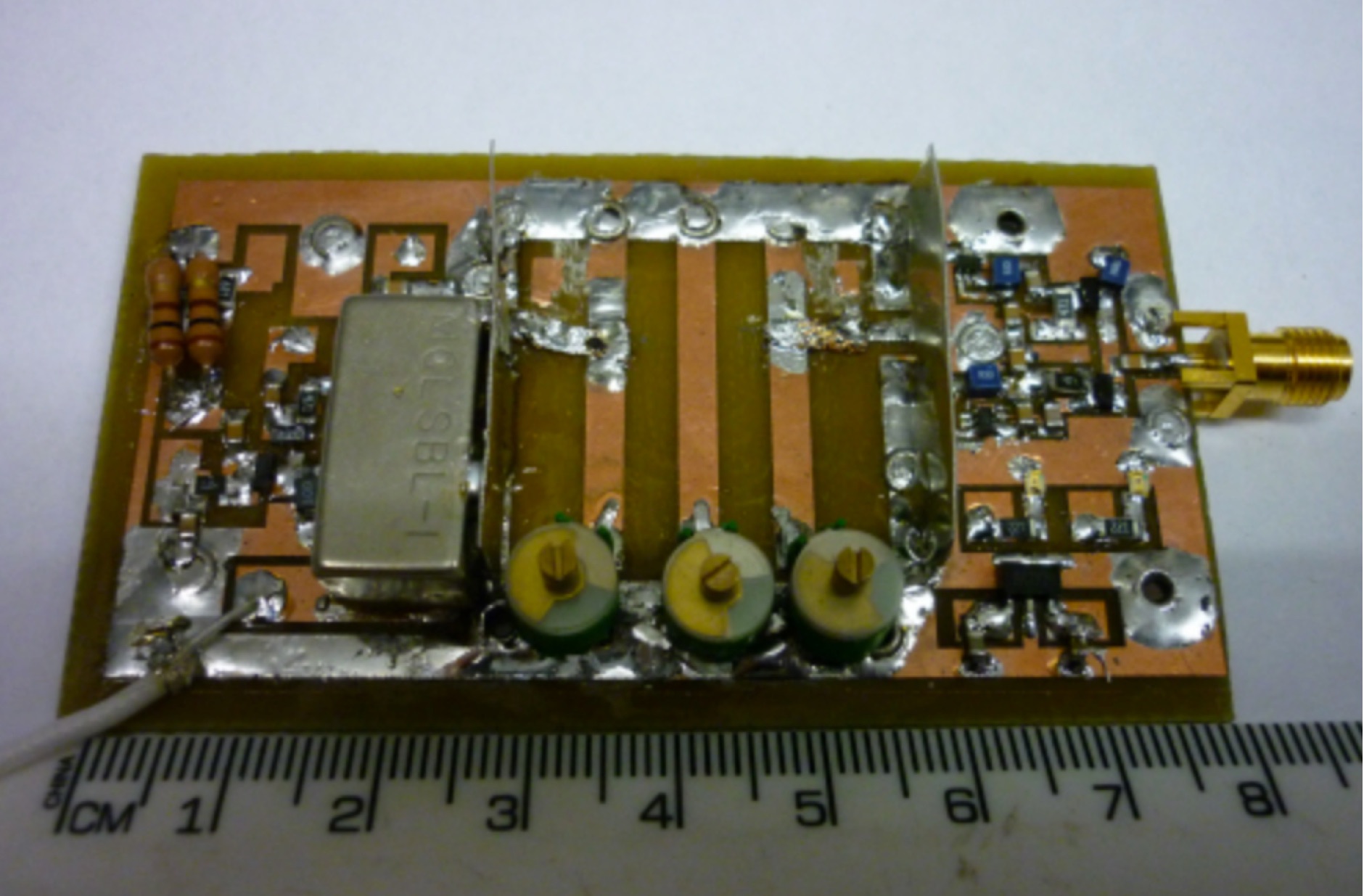
 This project describes a DIY all band HF SDR transceiver. Built around a Softrock 6.3 kit, it boasts a 20W homebrew amplifier and ATmega168 microcontroller for USB control. An LCD displays frequency, power, and SWR. Automatic LPF selection and SWR protection enhance functionality. Compatible with Rocky and PowerSDR software, this project provides a cost-effective and powerful HF SDR transceiver for hobbyists.
 -
 DataBridge wireless RF modem modules facilitate point-to-point data transmission, supporting analog, digital, and serial RS232 UART signals. These modules are engineered for robust wireless communication, offering a reliable solution for various industrial and amateur radio applications requiring secure data links. The product line includes specific models designed for different frequency ranges and power outputs, ensuring compatibility with diverse operational requirements. Each module integrates advanced RF technology to maintain signal integrity over distance, crucial for remote monitoring and control systems. The design emphasizes ease of integration, allowing users to quickly deploy wireless data links without extensive configuration. Key features encompass low power consumption and a compact form factor, making them suitable for embedded systems and portable devices.
 -
 Low-frequency (LF) radio time signals, operating primarily in the 40–80 kHz range, are broadcast by national physics laboratories for precise clock synchronization. Transmitters like **JJY** (40 kHz, 50 kW; 60 kHz, 50 kW), RTZ (50 kHz, 10 kW ERP), MSF (60 kHz, 15 kW ERP), WWVB (60 kHz, 50 kW ERP), RBU (66.66 kHz, 10 kW), and DCF77 (77.5 kHz, 50 kW) cover vast geographic areas, often several hundred to thousands of kilometers. LF signals offer distinct propagation advantages over higher-band transmissions such as GPS. Their long wavelengths (3–6 km) enable effective diffraction around obstacles like mountains and buildings. The ionosphere and ground act as a waveguide, eliminating the need for line-of-sight and allowing a single powerful station to cover extensive regions. Ground wave propagation minimizes ionospheric variability effects on transmission delay, and signals penetrate most building walls effectively. Robust and low-cost receivers, often priced at 20–30 USD/EUR, are widely used in radio clocks. These receivers typically comprise a tuned ferrite core antenna, a receiver IC (e.g., Atmel T4227, U4223B, MAS1016) for amplification and AM detection, and a microcontroller for decoding the time signal and phase-locking a local clock. Specific components for DCF77, MSF, and WWVB are readily available from vendors like HKW Elektronik and Ultralink.
 -
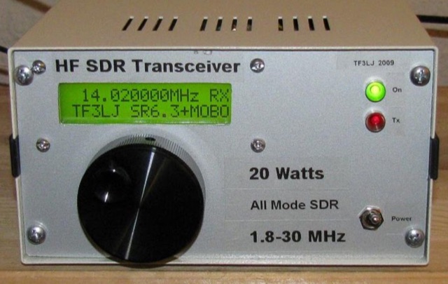
 Receive and decode SSTV amateur radio SSTV signals with this small and powerfull SSTV decoder app for Android devices. Requires access to microphone.
 -
 Thsi article describes a microcontroller driven semi-automatic antenna tuner capable of handling power levels up to 150 watts. The device is a low pass filter tuner manually tuned by setting the optimized L/C combination by hand and then storing the values into the EEPROM of the mictrocontroller to recall them later (seperately for each band from 80 to 10 meters including WARC bands)
 -
 An article on origin and usage of the Decibel, that has always been a logarithmically based representation of a power ratio
 -
 High Speed Multimedia (HSMM) radio, as introduced by John Champa, K8OCL, represents a significant advancement in amateur radio's digital capabilities, moving beyond traditional keyboard modes like packet radio. This initiative, driven by ARRL's Technology Task Force, focuses on developing high-speed digital radio networks capable of up to 20 megabits per second. HSMM primarily facilitates digital voice (DV) and digital video (ADV), enabling real-time video transmission from emergency scenes to an EOC without expensive ATV gear, often requiring only a laptop, a PCMCIA card, a digital camera, and a small antenna. The working group's initial efforts concentrate on cultivating microwave skills within the amateur community to build and support portable and fixed high-speed radio-based local networking, or **RLANs**. These networks prove invaluable for RACES and ARES organizations, as well as homeland security and other emergency communications. Field Day exercises and simulated emergency tests (SETs) are encouraged to hone skills in rapid site surveys and deploying broadband HSMM microwave radio networks, with examples like linking Field Day logging stations or antenna test results at the Midwest VHF-UHF Society Picnic 2003. Getting started with HSMM often involves adapting off-the-shelf **IEEE 802.11** (WiFi) equipment to comply with amateur radio regulations, typically operating in the 2.4 GHz ISM bands. While consumer WiFi gear has range limitations under Part 15 rules, proper setup under amateur regulations can extend coverage significantly, with test networks like the Hinternet achieving 5-15 mile ranges at 54 M bit/s using small mast-mounted dish antennas. Careful selection of equipment with external antenna ports, high transmit power, and low receive sensitivity is crucial, along with using low-loss coaxial cable like LMR-400 for optimal performance at these frequencies.
 -
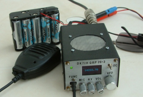 DK7IH QRP transceiver for 14 MHz. This small and compact home made transceiver with a max power output of 5W, the VFO module is based on the clock oscillator chip Si5351A by Silicon Labs ATmega168 and OLED 1306
 -
 An article by MicroHam on using the Icom PW-1 RF Power Amplifier safely and with non-Icom transceivers.
 -
 The _RS Group_ (formerly Distrelec) provides a comprehensive online store for electronic components, catering to both industrial and amateur radio needs. This resource offers a wide array of parts, including semiconductors, capacitors, resistors, relays, sensors, and power supplies, essential for constructing and maintaining amateur radio equipment. The platform emphasizes efficient procurement and features various top-level categories for easy navigation, such as **Sensors** with 33 subcategories and **Relays** with 13 subcategories, supporting diverse project requirements. Beyond component sales, RS Group offers services like ISO- and DAkkS-certified calibration for over a thousand measuring devices, and e-procurement solutions for businesses. The site also promotes _DesignSpark_, a community and software suite for electronic designers, aiding in the realization of design ideas. This integration aims to provide enhanced local support and a broader product selection, facilitating everything from basic circuit builds to complex industrial automation projects.
 -
 From buying an amateur radio transceiver, choosing the correct power supply, selecting the antenna and its feed line, to choosing the best microphone and accessories. A nice presentation for beginners.
 -
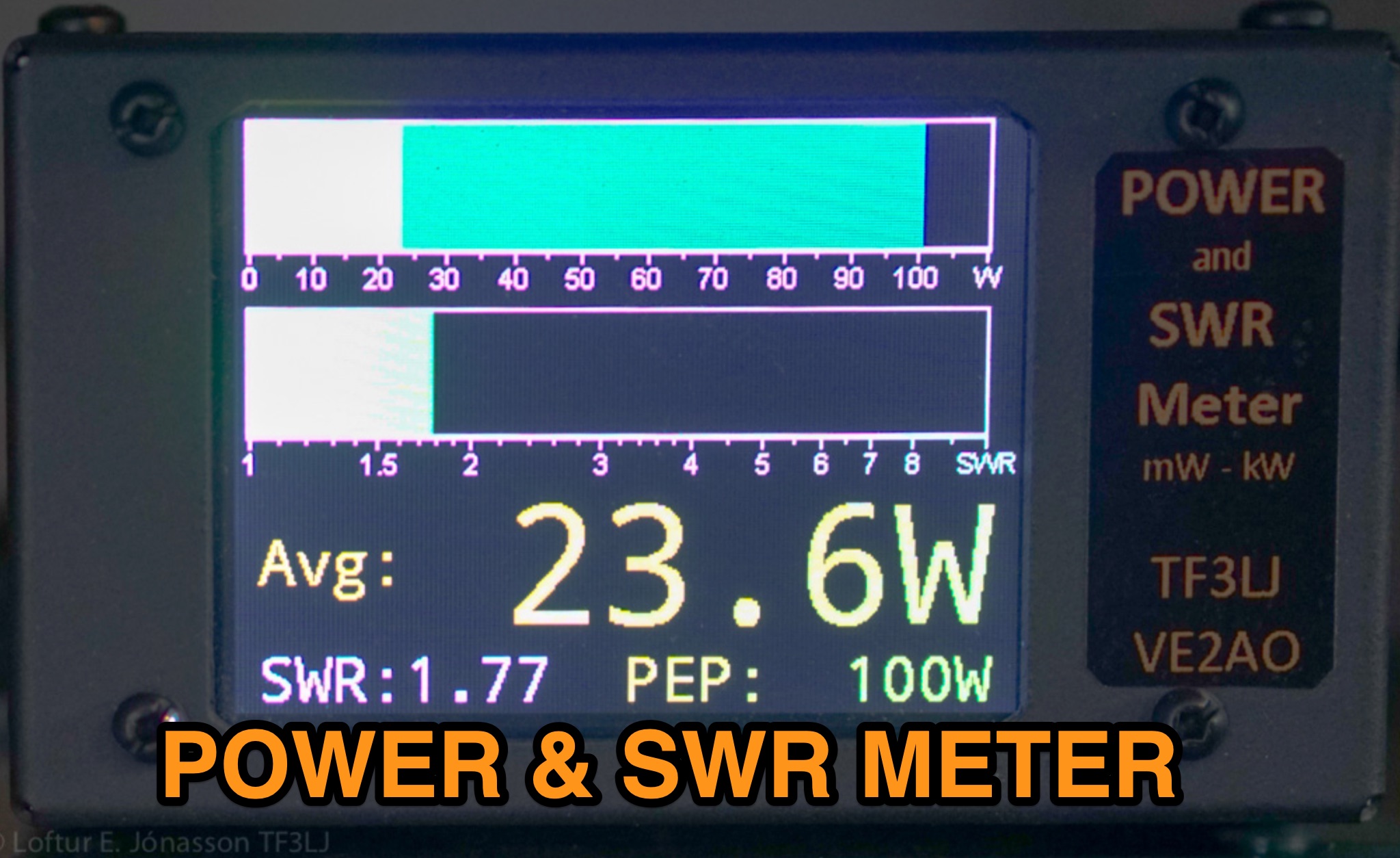 This page describes an update to a project for a Power and SWR Meter for ham radio operators. The update includes a more powerful microcontroller, increased sampling rate, and improved display options. It explains how to use the new components and provides detailed instructions for building the updated meter. The page also offers alternative display options and includes the full source code for the firmware. Overall, this update enhances the functionality and performance of the Power and SWR Meter project, making it more versatile and user-friendly for hams looking to measure RF power and SWR in their radio setups.
 -
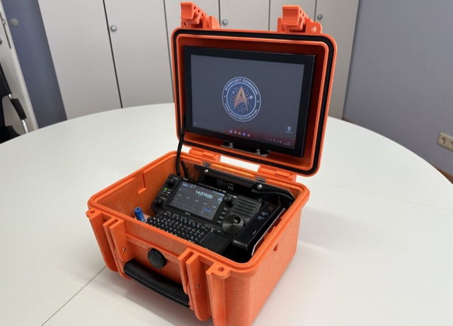 This project details the creation of a portable GoBox housing an IC705, Windows 11 PC, and Bluetooth microphone. The robust setup, enclosed in a weatherproof Hofbauer Explorer Case, ensures stability and functionality for QRP and emergency radio activities. The aluminum-mounted devices minimize RF interference, and a built-in LifePO4 battery powers the 10.1 TFT touch LED monitor, providing approximately 12 hours of use in receive mode. With a focus on grab-and-go versatility, this GoBox stands as an efficient solution for outdoor ham radio operations.
 -
 Presents two distinct hardware modifications for the Icom IC-7300 transceiver, detailing the necessary steps for each. The first modification, a _MARS_ transmit expansion, involves the physical removal of specific surface-mount diodes (D422) from the main board, enabling transmit capabilities across a broader frequency range, including out-of-band frequencies. It specifies the diode location on US versions of the IC-7300 and suggests using small diagonal cutters if a soldering iron is not preferred or available. The second modification focuses on the internal antenna tuner, aiming to provide wider impedance matching capabilities. This involves adding a **100k ohm** resistor to a designated point within the tuner circuit. The resource also briefly mentions a microphone modification for the _HM219_ and a general power increase, though without specific instructions for the latter two. It emphasizes safety precautions, such as disconnecting power and inspecting the work area.
 -
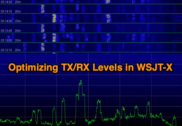 Exploring digital radio modes, the author rethinks how to adjust transmit and receive levels in WSJT-X. Despite effective communication using Yaesu's settings, a new procedure aims for better performance. For RX, set audio device levels to 100%, disable AGC, and adjust RF gain. For TX, enable "Remember power settings" and adjust power output to avoid ALC engagement. This method ensures reliable communication without signal degradation, enhancing dynamic range and minimizing noise.
 -
 A homebrew spectrum analyzer, the Specan, provides a crucial measurement capability often missing from the typical amateur radio shack, allowing for detailed analysis of RF signals up to 70 MHz. This double-conversion superheterodyne receiver design incorporates 112 MHz and 12 MHz intermediate frequencies, utilizing an _Si570_ as the local oscillator for fine tuning down to 1 Hz steps. It offers two resolution bandwidths: 300 KHz for broad spectrum sweeps and 1 KHz for precise close-in distortion measurements, achieving an 80 dB spur-free dynamic range at 1 KHz resolution. The project, a reboot of the classic _W7ZOI/K7TAU_ design from November 1998 QST, integrates an _Arduino_ microcontroller for controlling the Si570, managing a front-panel LCD, and communicating with a PC for spectrum plotting. This approach significantly reduces cost compared to commercial units, making advanced RF diagnostics accessible to homebrewers. The Specan can measure carrier suppression, VFO cleanliness, antenna VSWR, transmitter harmonics, and filter passband shapes, providing insights beyond what an oscilloscope or frequency counter can offer. Construction emphasizes modularity and careful shielding, with each stage built and tested individually on unetched copper clad board. The design includes detailed instructions for integrating the Arduino, building the Si570 oscillator, and aligning the various modules, often using the Specan itself for calibration. It requires a well-regulated linear power supply and can be built with common tools and readily available components, making it a practical and rewarding endeavor for those looking to enhance their RF test bench.
 -
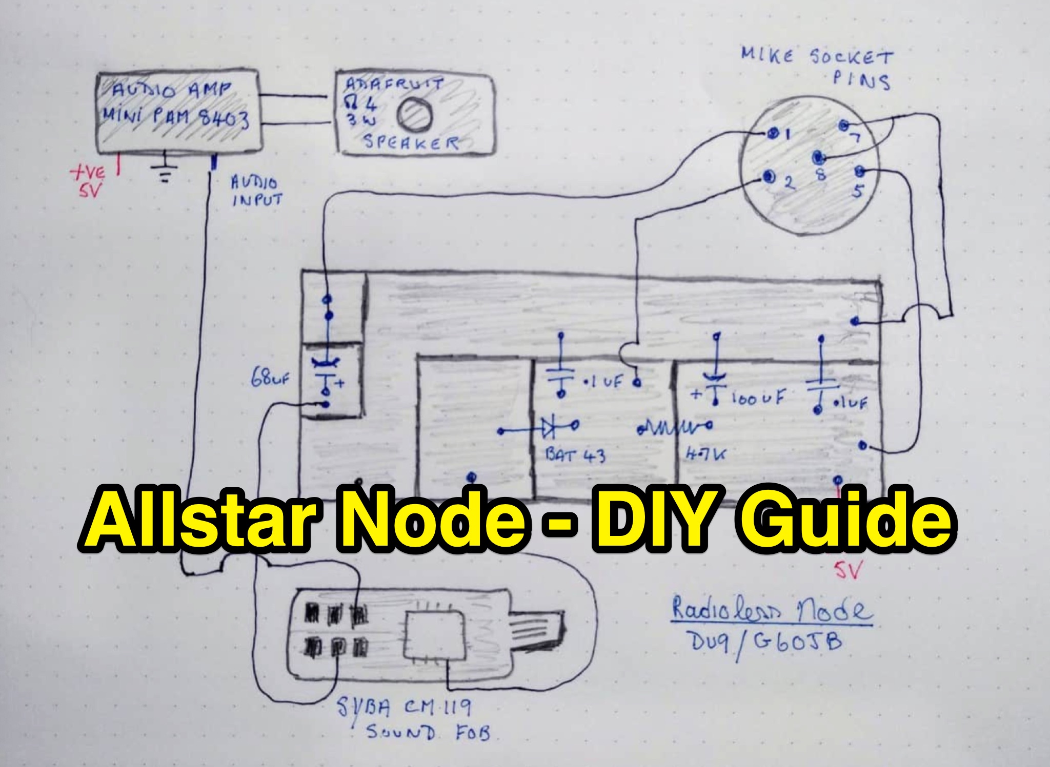 This page provides a detailed guide on how to build your own radioless Allstar node for ham radio operators. It includes information on power supply, components needed, wiring instructions, and tips to avoid common issues like ground loop hums. The author shares personal experiences and recommendations for specific components like microphones, audio amps, and sound fobs. Whether you're a beginner or experienced ham radio operator, this DIY project can help you set up a cost-effective and functional Allstar node for communication purposes.
 -
 An **Arduino LC Meter** provides an accessible solution for precisely measuring inductance and capacitance values, crucial for RF circuit design, filter tuning, and troubleshooting in amateur radio applications. This project details the construction of a low-cost, accurate instrument using readily available components, making it an attractive alternative to commercial units for hams and electronics enthusiasts. The build process involves assembling a resonant circuit, integrating an Arduino microcontroller for frequency measurement, and displaying results on an LCD. Key components include an Arduino Uno, a 16x2 LCD, a 74HC14 Schmitt trigger inverter, and a few passive components. The design leverages the Arduino's processing power to calculate L and C values from resonant frequency shifts. Calibration procedures are outlined to ensure measurement accuracy, which is vital for critical RF work. The project includes schematics, a parts list, and the necessary Arduino code, enabling hams to construct a functional LC meter for their workbench.
 -
 This Arduino project explores long-range RF communication using EBYTE E32 1W LoRa modules (either E32-915T30D or E32-900T30D) paired with ESP32 microcontrollers featuring OLED displays. The setup leverages the modules' Semtech SX1276 chip with amplifier to achieve up to 1W transmission power—significantly more than the chip alone provides. Unlike other LoRa implementations, these modules include a microcontroller that simplifies interface through UART rather than SPI. The documented implementation includes proper wiring between components and Arduino code that configures the module, displays received messages on the OLED screen, and transmits messages every two seconds while keeping power consumption manageable.
 -
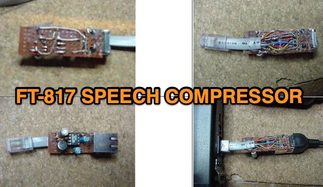 Designed for the FT-817, this audio speech compressor, centered on the Analog Devices SSM2165, offers a 40 dB compression range, enhancing signal power. Built externally with the SMD version to preserve warranty, the circuit interfaces smoothly with electret microphones. Testing shows a 6 dB average power increase. Adaptable to rigs with electret microphones, it maintains unity gain and 40 dB compression.
 -
 Many low-power SSB rigs and kits lack dedicated speech processor circuitry, although most modern HF rigs include it. Speech processing is crucial for low-power SSB to overcome QRM. This simple, low-cost circuit integrates a microphone element and can be housed in a defunct desk mike. It features a feedback amplifier, audio preamplifier, and adjustable speech compression control
 -
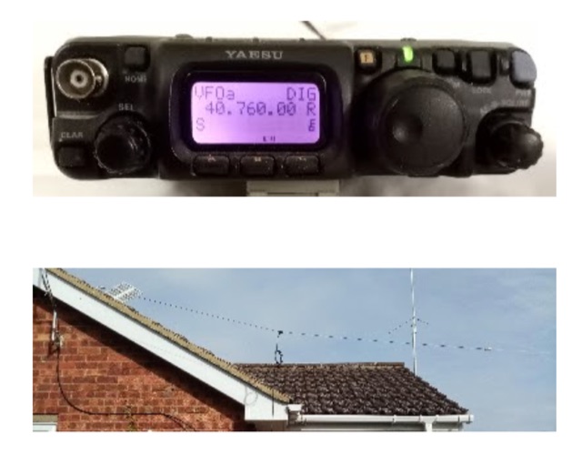 The 8m ISM band, a unique frequency range between 10m and 6m, holds potential for amateur radio enthusiasts, yet it remains largely unallocated. This spectrum offers fertile ground for research and self-training. The author's experience with low-power transmissions and WSPR testing highlights the band's capabilities and the need for a narrow, speech-free amateur allocation to encourage experimentation. Discover the world of 8m ISM radio exploration and its future possibilities.
 -
 Learn how to build a simple transmitter called the 'Easy Ten' that can be easily heard at a distance of 10 miles using a random length wire antenna thrown into a tree. This article focuses on working with frequencies in the 3.5 and 7 MHz range without the need for complex setups like coax lines or baluns. The author shares their experience of making contacts across the Pacific Ocean and the United States using just one watt of output power and simple antennas. Discover how to optimize signal output using a homemade level meter made from a DC microameter and a germanium diode.
 -
 In an innovative analysis, Michael G7VJR employs NeuralProphet to predict ham radio modes' usage trends. The AI model, leveraging deep learning, forecasts a steady FT8 dominance, with slight declines in CW and Phone activities. This approach simplifies statistical predictions, showcasing the power of AI in understanding complex patterns and facilitating insightful time series projections. Access the freely available Club Log data for continuous exploration.
 -
 The resource details the construction of a 433 MHz LoRa APRS iGate and a tracker, both built around _TTGO T-Beam v1.1_ microcontroller boards. Each board integrates an OLED screen, WiFi, GPS, and an SMA antenna connector, powered by an 18650 3.7 V lithium-ion battery or microUSB. The iGate operates on 433.775 MHz, with its status verifiable on aprs.fi, demonstrating practical implementation of LoRa-based APRS solutions. The methodology involves programming the modules using Visual Studio Code with the PlatformIO plugin. This process loads the necessary firmware and a JSON configuration file, which includes the operator's callsign and WiFi credentials for the iGate. The guide emphasizes the ease of programming and provides specific steps for configuration. Initial testing of the iGate and tracker, including smart beaconing configuration, is documented. The low power output of approximately 200 mW from the LoRa board's transmitter is noted, with suggestions for range extension through improved antennas or RF amplification. The author, N4MI, plans to deploy a higher-gain 70cm antenna for the iGate.
 -
 Noise-canceling electret condenser microphones (ECMs) are ideal for compact, battery-powered devices due to their small size, low power consumption, and high sensitivity. These microphones, used in conjunction with active noise cancellation circuitry, significantly reduce ambient noise, creating a more peaceful listening experience by combining and processing signals from multiple microphones.
 -
 The article by Guy Olinger, K2AV, published in the May/June 2012 National Contest Journal, introduces the Folded Counterpoise (FCP), a compact 516-foot single-wire counterpoise elevated at 8 feet, designed for 160-meter operations on small lots like 100x150-foot backyards. Originating from efforts to revive Top Band for W0UCE on a postage-stamp property, the FCP uses strategic folds to cancel ground fields within 33 feet of center, minimizing losses to 0.13-0.53 dB—outperforming sparse or on-ground radials by up to 15 dB in poor soil—while mimicking opposed radials for efficient feedpoint impedance. Paired with a critical 1:1 or 4:1 isolation transformer (e.g., trifilar on T300-2 toroid) to block common-mode currents on coax feeds, it delivers proven results: K2AV's #8 North America low-power contest score, 7+ dB gains at W4KAZ and K5AF, and over 10,000 global web hits for DIY instructions using bare 12 AWG wire and weatherproof enclosures. Ideal for acreage-challenged hams, the FCP also excels on 80 meters with scaled dimensions, offering a low-loss alternative where full radials are impractical
 -
 Single-sideband (SSB) radio enhances spectral efficiency but poses challenges with audio intelligibility, particularly in noisy conditions. A microphone audio compressor addresses these issues by dynamically managing the audio signal’s dynamic range. It amplifies quiet sounds and attenuates loud ones, ensuring consistent audio levels for improved clarity. Benefits include increased intelligibility, higher average power, and reduced spurious emissions. While essential for optimal SSB performance, careful parameter adjustment is crucial to balance natural sound quality and effective communication across various operating modes.
 -
 Effective suppression of harmonics and parasitic radiation from HF transmitters is crucial, especially with the increasing sensitivity of VHF/UHF radio channels to interference. This project details a hybrid low-pass filter (LPF) designed to operate across the HF bands up to 51 MHz, making it suitable for 6-meter band operations while providing deep VHF/UHF suppression. The design addresses the challenge of modern interference landscapes, where even microvolt-level signals can disrupt wireless sensors and other simple VHF/UHF receivers. The filter utilizes a single elliptic link, combining high cutoff steepness with robust suppression in the hundreds of megahertz range. A key feature is the use of only two standard capacitor values, simplifying construction and component sourcing. The article provides a detailed schematic, performance characteristics, and _RFSim99_ model file, demonstrating a reflection coefficient S11 below 0.017 (VSWR < 1.03) across 1-51 MHz, ensuring minimal degradation to the antenna system. Construction notes include coil winding specifications and capacitor selection guidance, with recommendations for _FR-4_ assembly. Two capacitor sets are presented, with the first variant recommended for its lower RF current demands, keeping currents below 3 A at 1 kW passing power at 51 MHz. Fine-tuning involves adjusting frameless coils, with considerations for capacitor tolerance and high-frequency capacitance measurement accuracy.
 -
 The DIY Power Meter project utilizes the _INA226_ high-side power monitoring chip, paired with an ATtiny85 microcontroller, to measure voltage, current, and power, displaying the results on a 128x32 OLED screen. The INA226 communicates via an I2C interface and is programmed with a calibration factor based on the shunt resistance and current register LSB. The project is designed to handle a maximum current of 500mA using a 0.16ohm shunt resistor, which can be adjusted to a 0.2ohm resistor, reducing the full-scale current range to 409mA with a resolution of **12.5uA**. The shunt resistor dissipates only 33mW at maximum current, making 1/4 watt resistors suitable for the setup. The PowerMeter.ino sketch configures the shunt resistance and maximum design current, automatically calculating the calibration factor. The project can be prototyped on a breadboard using an Arduino Uno, employing the Wire library for INA226 and OLED communication, and the u8g2lib library for the OLED display. For the ATtiny85 version, the Adafruit-TinyWireM and Tiny4kOLED libraries are used. The power meter is independently powered by a 3V CR2032 cell, with power switching options including manual switches or DC switched jacks. The low-side n-channel MOSFET switch configuration is tested but introduces voltage drop issues, making manual switching a more reliable option until a suitable DC switched jack is found. DXZone Technical Profile: INA226 | ATtiny85 | OLED Display | Power Meter
 -
 Elektrodump.nl is an online shop from the Netherlands specializing in amateur radio products. It offers a wide range of categories including antenna masts, antennas, tuners, coax connectors, and cables. The site also features broadcast equipment, electron tubes, semiconductors, and various electronic components like capacitors and resistors. Additionally, it provides measuring equipment, power supplies, and transmitters, catering to both hobbyists and professionals in the field of radio electronics.
 -
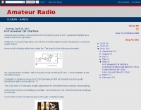
 Integrating a _Software Defined Radio_ (SDR) into an existing ham radio setup involves connecting it with a standard transceiver (TRX), power amplifier (PA), and antennas. The core component is a splitter box that facilitates the connection between the TRX and the SDR, allowing for simultaneous operation without modifying existing equipment. In receive mode, the splitter ties the antenna inputs of both the TRX and a direct conversion receiver (DC RX) together. During transmission, the DC RX input is grounded via a fast telecom relay controlled by the transceiver's -SEND signal, incorporating a 10ms delay for safety. The splitter box includes a 3.7 dB input attenuator for impedance matching and acts as a protective fuse for the DC RX input. Ground loops are mitigated using common mode balun transformers, while the DC RX input is insulated with a broadband transformer. An audio switch box complements the setup, enabling users to listen to either the main transceiver, the SDR output, or both simultaneously. This configuration ensures noise immunity and safety, with the splitter housed in a screened box made from PCB material. On-air tests, such as the CQ WW 160m CW DX Contest, demonstrate the system's effectiveness, showcasing the SDR's ability to handle crowded band conditions with superior selectivity and dynamic range. The SDR's narrow bandwidth filters and waterfall display provide significant advantages, allowing operators to detect weak signals amidst strong interference. The integration of SDR with conventional radios offers enhanced operational flexibility and performance in challenging environments.
 -
 This project presents a compact QRP SWR meter featuring a 0.96" OLED display (128x64 pixels) for high-contrast visibility, updated with software fixes for display compatibility, improved low-power performance, and support for ATtiny45/85 microprocessors. A 1.3" OLED version accommodates visibility needs. Designed for HF QRP transmitters (3-15W), it uses a Breune coupler with germanium diodes for accurate SWR measurement. Powered by a AAA battery, the meter offers a standalone solution for impedance matching, with a 3D-printed enclosure enhancing portability.