Search results
Query: receiving antenna
Links: 104 | Categories: 9
-
 Hi-Z Antennas offers specialized high-impedance receiving systems, primarily focusing on phased vertical arrays for HF reception. Their product line includes preamplifiers designed for shortened vertical antennas, featuring optimized 15dB gain and array-matched characteristics. These components are engineered to enhance weak signal reception and improve signal-to-noise ratio across the HF spectrum. The company provides controllers for managing multiple vertical elements in a phased array configuration, enabling directional reception patterns. These systems are particularly effective for mitigating local noise and interference, a common challenge in urban and suburban operating environments. Specific offerings include solutions for 160-meter and 80-meter bands, addressing the unique requirements of low-band DXing. Technical details often reference components like the 2N3866 transistor in preamp designs and discuss concepts such as out-of-band attenuation. The focus remains on optimizing receiving antenna performance through impedance matching and active amplification, rather than transmit capabilities.
 -
 Demonstrates a range of specialized radio frequency equipment and consulting services for amateur and professional applications. The offerings include _Vector-Finder_ direction finding antennas, various test equipment such as _gate dip meters_ and RF sniffers, and communications receiving adjuncts. Additionally, the company produces satellite antennas for weather satellite reception, voice amplification devices like the _Flex-Mike_, and custom prototype circuit boards. The company's product line addresses needs for precise RF measurement, signal detection, and specialized antenna systems, particularly for direction finding and satellite communications. Their historical association with National Radio (HRO) suggests a legacy in radio technology. The site also highlights a subsidiary, Sierra Mountain Products, which offers outdoor recreational gear, indicating a diversification beyond core RF manufacturing.
 -

-
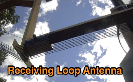 A receiving loop antenna for low frequency DX Work
 -
 RF Systems develops and produces antennas and accessories for governmental and military organisations, shortwave and scanner listeners, radio amateurs, yachting circles and professional users of receiving and transmitting equipment.
 -
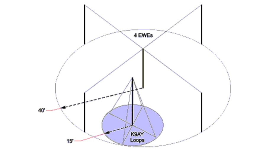
 Optimizing weak signal reception on the HF bands, particularly in the presence of strong local QRM, often necessitates specialized receiving antenna systems. This resource details the _HI-Z Antennas_ product line, focusing on phased vertical arrays designed for superior noise rejection and directivity. It covers components such as the 4-Square and 8-Element array controllers, which allow for rapid switching of receive patterns, and dedicated low-noise preamplifiers to improve system sensitivity. The site also presents various bandpass filters, crucial for mitigating out-of-band interference and enhancing the dynamic range of the receiver. The HI-Z systems are engineered to provide significant front-to-back and side rejection, often yielding **20-30 dB** of attenuation to unwanted signals, which is critical for DXing and contesting. Users can achieve a notable reduction in local noise, allowing for the discernment of signals that would otherwise be buried. The array controllers facilitate quick pattern changes, enabling operators to null out interference or peak weak signals from distant stations, effectively extending the reach of their receive capabilities by improving the signal-to-noise ratio.
 -
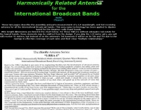 The HarRe antenna series, multi element quarter wave resonant broadcaters band receiving antenna
 -
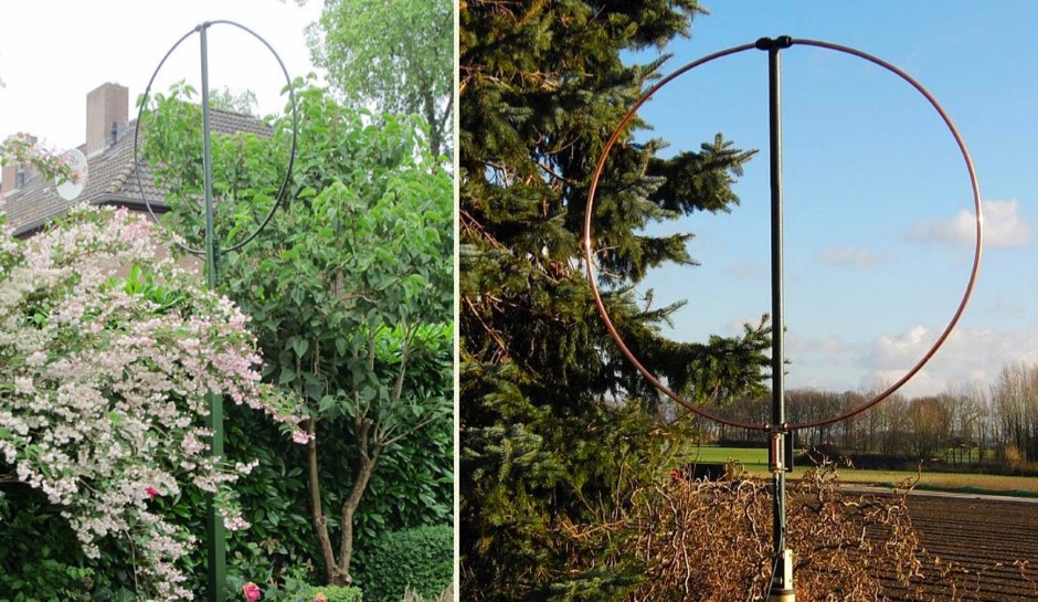 A shielded broadband (~200 MHz) active loop antenna offers more quiet and relatively less interference reception.
 -
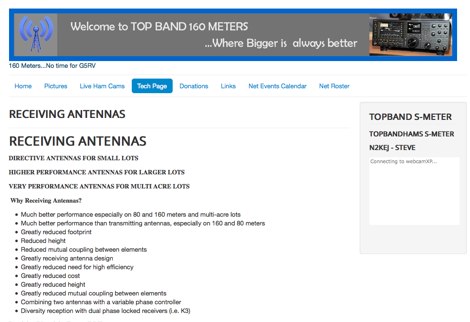 A review of all possible receiving antennas for top band 160 meters
 -
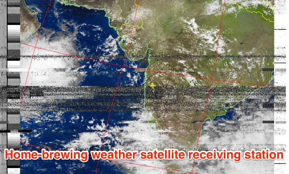 The page provides a detailed guide on how to build your own NOAA weather satellite receiving station, covering hardware, antenna, computer setup, and software installation. It offers a straightforward explanation suitable for beginners and serves as an educational project. The content includes step-by-step instructions and tips for observing satellites in the night sky.
 -
-
 Low Band Receiving Antenna, it is a ground independent Receiving antenna which only needs two 10m support poles by DH1TW
 -
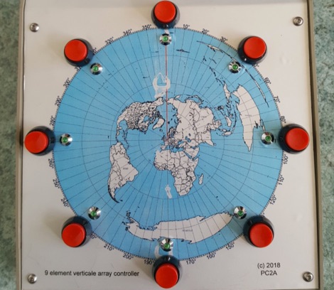 The receiving antenna setup for the top band, made with a 9 elements vertical antenna array, remote controller and remote relais.
 -
 In this article the author shows the receiving loop antenna for 160 meters band installed at his QTH. Diagram and movie available. Article in in Turkish but can be translated in english
 -
 Notes on how to properly install a Mini Whip receiving antenna in an noisy urban environment.
 -
 Amateur Television (ATV) operations involve transmitting and receiving live or recorded video and audio signals over amateur radio frequencies. Unlike narrow-band modes, ATV utilizes a wider bandwidth to convey video information, often requiring specialized transceivers, antennas, and signal processing equipment. This mode allows hams to share visual content, demonstrate projects, or conduct video conferences, typically on VHF, UHF, and microwave bands due to the bandwidth requirements. The SwissATV resource focuses on the technical aspects and community engagement surrounding ATV within Switzerland. It covers topics relevant to setting up ATV stations, understanding signal propagation at higher frequencies, and participating in local ATV activities. The site serves as a central point for Swiss ATV operators to exchange knowledge and coordinate transmissions, fostering the growth of this specialized amateur radio mode.
 -
 Sixty-meter repeaters typically use a 1 MHz frequency separation between input and output, while 2-meter repeaters commonly employ a **600 kHz** split and 70-centimeter repeaters use a **5 MHz** offset. This article details the fundamental technical principles of amateur voice repeaters, explaining how they extend VHF/UHF communication range by receiving on one frequency and simultaneously retransmitting on another. It covers essential components such as receivers, transmitters, filters, and antennas, often situated on elevated locations for optimal coverage. The resource delves into the critical challenge of _desensing_—where the repeater's strong transmit signal overpowers its own receiver—and the engineering solutions employed, including antenna separation and the use of high-Q cavity filters. It also explores various control and timing systems, from basic squelch activation to more sophisticated microcontroller-based boards that manage functions like voice identification, time-out timers, and fault protection. Different access methods are discussed, including open access, toneburst, CTCSS subtone, and DTMF, each offering distinct advantages for managing repeater usage and mitigating interference. Furthermore, the article examines repeater linking, both conventional RF methods and modern internet-based solutions, highlighting how linking expands coverage and promotes activity across multiple repeaters or bands. It introduces less common repeater types such as 'parrot' repeaters, which use a single frequency and digital voice recording, and linear translators, capable of relaying multiple signals and modes simultaneously across different bands, often found in amateur satellites.
 -
 Designing and constructing a two-element receiving loop antenna array for HF operation involves specific considerations for achieving high directivity and noise reduction. This resource details a homebrew system comprising two 30-inch diamond-shaped loops, spaced 20 feet apart, which are fed through mast-mounted preamplifiers and passive signal combiners. The operational principle relies on adjusting phase delays between elements via precise _Belden 8241_ coaxial cable lengths, optimized for specific bands from 160m to 20m. Performance data, derived from _EZ-NEC_ modeling, illustrates consistent 90° azimuth-plane beamwidth and low take-off angles across the target bands, with _Receiving Directivity Factor_ (RDF) values comparable to a 300-foot Beverage antenna. The article presents detailed elevation and azimuth plots for 20m, 30m, 40m, 80m, and 160m, demonstrating the array's ability to provide strong response at low DX angles while also supporting _NVIS_ signals. Key components like the _DX Engineering RPA-1_ preamplifier and _DXE RSC-2_ signal combiner are discussed, alongside the importance of impedance matching to preserve antenna patterns. The construction emphasizes self-contained elements that do not require ground radials, offering a compact solution suitable for suburban environments and stealth installations, with a focus on optimizing receive performance independently from transmit antennas.
 -
 The video delves into the fascinating science behind antennas, which are crucial for receiving and transmitting electromagnetic waves. It explains how antennas convert electric signals into electromagnetic waves for transmission, and how they operate through the oscillation of positive and negative charges in dipole arrangements. Practical antenna implementations, such as dipole antennas for TV reception and Yagi-Uda antennas with reflectors and directors, are also discussed alongside modern dish TV antennas with parabolic reflectors for signal processing. It's a comprehensive overview of how antennas work and their significance in communication technology.
 -
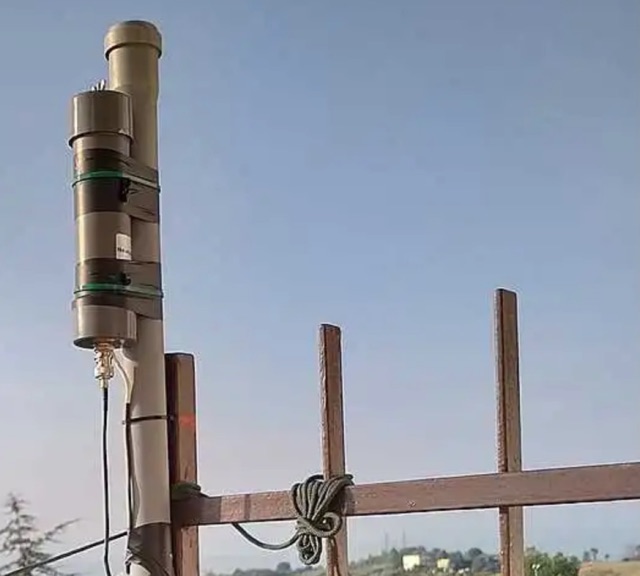
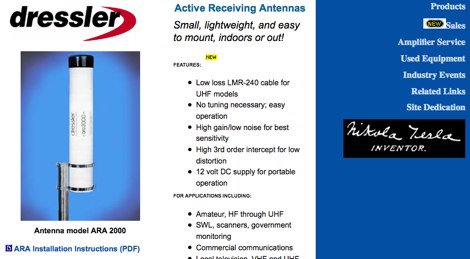 Active Receiving Antennas, designed for reception of shortwave, mediumwave and longwave signals and VHF/UHF signals
 -
 This article presents an innovative homebrew antenna design utilizing surplus ladder line as a receiving antenna for HF and MF bands. The Ladder Line Antenna (LLA) transforms standard 450-ohm ladder line into a directional, bidirectional, or omnidirectional antenna system through different termination methods. The design, which requires minimal space and height, achieves 6-10dB front-to-back ratio on 40-160m bands using a 33-foot length. This DIY wire antenna project offers an efficient, low-profile solution for amateur radio operators, featuring broadband operation without ground radials and easy installation below fence height.
 -
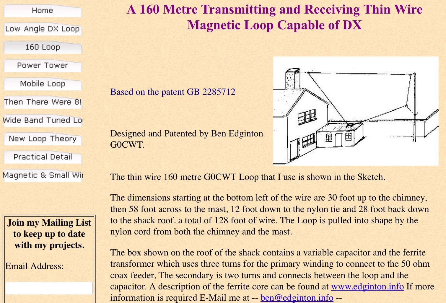 A 160 Metre Transmitting and Receiving Thin Wire Magnetic Loop Capable of DX. Designed and Patented by Ben Edginton G0CWT
 -
 On December 12, 1901, Guglielmo Marconi successfully received the first transatlantic wireless communication, a Morse code "S" (three dots), at 04:30 GMT. This article details the setup for this groundbreaking experiment, noting Marconi's receiver in St. John’s, Newfoundland, Canada, utilized a _coherer_ and an antenna elevated by balloons and kites. The transmitting station at Poldhu, Cornwall, England, featured twenty-four 200-foot ships' masts and a 25-kilowatt alternator. The resource explains how this contact disproved contemporary beliefs about radio wave limitations due to Earth's curvature, later understood through _ionospheric propagation_. It frames Marconi's achievement as the "very first DX" in amateur radio terms, defining DX as telegraphic shorthand for distance and _DXing_ as the hobby of receiving distant signals. The article also provides external links for further reading on Marconi's experiments and the science behind transatlantic radio signal reception.
 -
 Manufacturer of amplifier for small magnetic and electric receiving wideband antennas, and variable delay line kit for active antenna phased arrays
 -
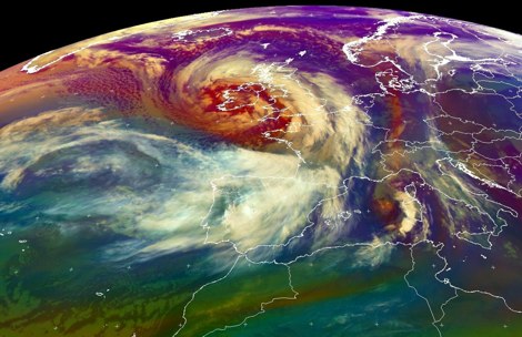 A Dutch website dedicated to weather satellite reception with many documents related to antennas, software and techniques on receiving signals from weather satellites.
 -
 Operating in a Single Operator Two Radios (SO2R) setup, especially with beverage antennas, often exposes the receiving radio's front-end to significant RF energy from the transmitting radio. This resource details a practical, homebrew receiver protection circuit designed to mitigate this risk. The core of the design involves a non-inductive 2W 22 Ohm carbon composition resistor in series with the RX antenna line, followed by two stacks of four fast-switching diodes (e.g., _1N914_) configured in opposite polarizations. This arrangement effectively clamps the incoming voltage to approximately 2.8 V peak-to-peak, safeguarding sensitive receiver input components. The series resistor plays a crucial role by absorbing excess power, preventing the diodes from exceeding their current ratings and potentially failing open, which would leave the receiver unprotected. The author, _N4KG_, measured up to 50 watts of coupled power between 80M slopers on the same tower, highlighting the necessity of such protection. The design is presented as a cost-effective solution to prevent damage to receiver input transformers, with the author noting successful protection of a receiver even after a resistor showed signs of overheating. This simple circuit can be integrated via a transverter plug, offering a robust defense against high RF input.
 -
 The DIY 137 MHz WX SAT V-dipole antenna project details the construction of a specialized antenna for receiving weather satellite transmissions. It provides specific dimensions for the dipole elements, designed for optimal reception around the 137 MHz band, which is commonly used by NOAA and Meteor weather satellites. The resource outlines the materials required, such as aluminum tubing for elements and PVC for the support structure, along with the necessary coaxial cable and connectors. The article presents a clear, step-by-step assembly process, including how to form the V-shape and connect the feedline. It emphasizes practical considerations for mounting and weatherproofing the antenna for outdoor deployment. The design focuses on simplicity and effectiveness for amateur radio operators interested in satellite imagery. Key aspects include the precise angle of the V-dipole and the lengths of the radiating elements, which are critical for achieving the desired circular polarization response for satellite signals. The resource includes photographic documentation of the construction phases and the final mounted antenna.
 -
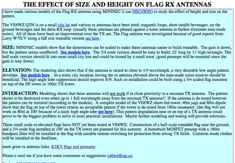 Analysis of flag receiving antennas using MININEC with focus on relation of size and atenna height by VE6WZ
 -
 Experimenting with capacitive antennas for 40 and 80 meters band. A very space-saving antenna with good receivings caracteristics
 -
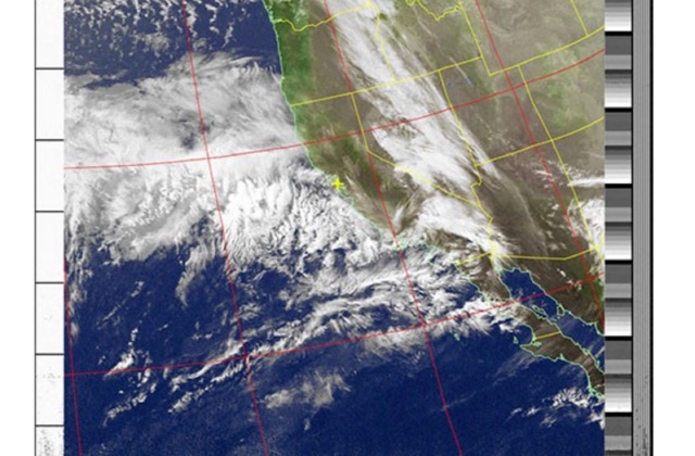 Receiving & Decoding NOAA Weather Satellites using a simple rtl-sdr dongle, a helix antenna and a Windows PC
 -
 An article about the Beverage antennas, super long wire receiving antennas thar are unidirectional and have a very low noise that makes this antenna excellent for low band dxing. By Thomas R. Sundstrom W2XQ, 73, June 1981, 73 Magazine
 -
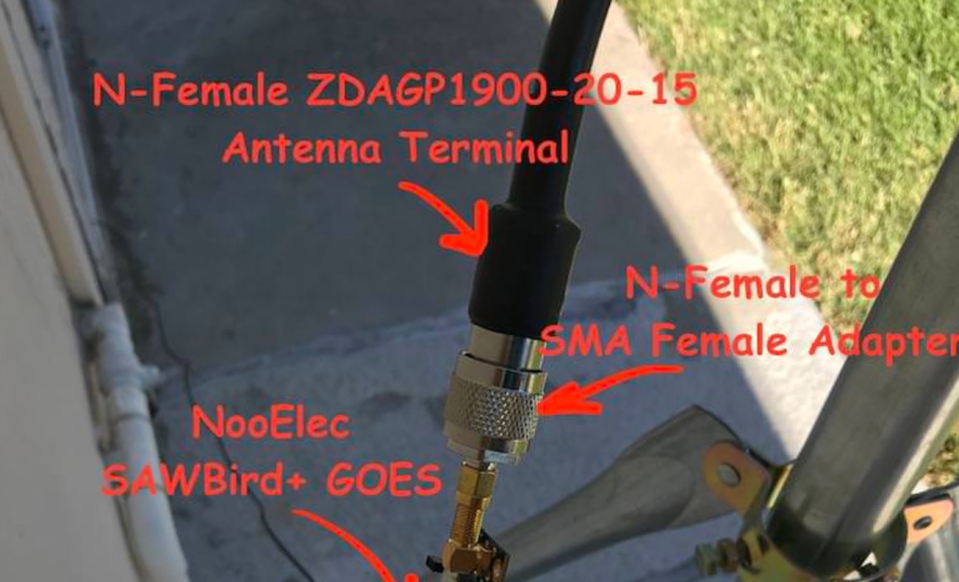 Receiving **GOES-16** and **GOES-17** weather satellite imagery requires a specific hardware and software configuration, detailed in this practical guide. The author outlines the necessary components, including a Raspberry Pi, an RTL-SDR dongle, a suitable LNA with SAW filter for 1.69 GHz, and a parabolic grid antenna. This setup enables direct reception of high-resolution weather data, a fascinating aspect of amateur radio satellite operations. The installation process begins with preparing the Raspberry Pi, followed by updating the system and installing essential dependencies like `git`, `build-essential`, and `cmake`. A critical step involves compiling and installing `librtlsdr` from source, ensuring proper driver setup and blacklisting conflicting DVB drivers. The guide then walks through testing the RTL-SDR dongle to confirm device recognition and troubleshoot common issues like USB power or driver installation problems. Finally, the instructions cover cloning and building `goestools`, a software suite essential for processing the satellite signals. This compilation, while time-consuming on a Raspberry Pi, is crucial for decoding the raw data into usable imagery. The guide concludes with the initial steps for creating the `goesrecv.conf` configuration file, preparing the system for active satellite reception.
 -
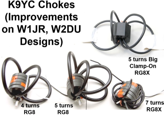 This is a small collection of K9YC info and my experiences. Problems by feed lines of 1/2 lambda length. CMCs in transmitting and receiving systems. Antenna unbalance, Maximal allowed power, Choke winding tips.
 -
 The video showcases the setup of a 300 MHz oscillator, a 100W radiofrequency amplifier, and a dipole antenna for transmitting radio waves, leading to the fluorescence of a nearby light bulb. It demonstrates the presence of standing waves on the dipole antenna and how intensity varies along its length. Additionally, the usage of a copper pipe as a receiving antenna is explored, showing changes in intensity depending on alignment and proximity to the transmitter. Finally, a B field antenna sensitive to magnetic fields is introduced, revealing brightness variations in different orientations. The video offers insightful observations on radio wave transmission and reception phenomena.
 -
 Learn about the practical design and construction of Yagi antennas for ham radio operators. This post explores the benefits of Yagi antennas in receiving and transmitting RF signals, concentrating signal energy in one direction for long-distance communication. Discover the theory behind Yagi antennae, the importance of element size and spacing, and the resources available for sizing and construction. Whether you're interested in OTA television or amateur radio communication, understanding Yagi antenna design can enhance your signal reception and transmission capabilities.
 -
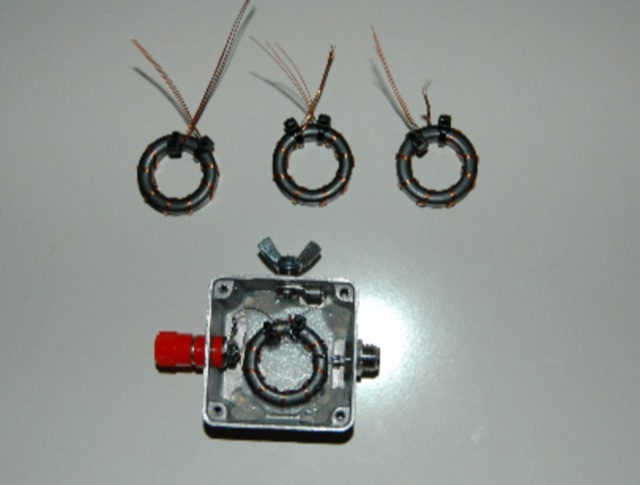
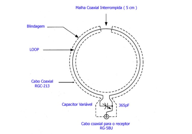 This page is a project for a small loop antenna for reception of short wave broadcasting. It is in Portuguese and contains pictures and schematics to build your own antenna
 -
 WB8LZR details the construction and initial field results of a multi-band vertical wire antenna, designed to complement his existing horizontal loop for improved DX on 80 meters. The antenna utilizes a 67-foot vertical wire, configured as a quarter-wave radiator on 80m, and employs a 1:1 current balun for RF isolation on 80m, 30m, and 17m. For bands like 40m, 20m, and 10m, where the wire acts as a half-wave or full-wave radiator, an additional impedance transforming _unun_ is integrated to manage the significantly higher feedpoint impedance and voltage. The author notes the vertical's performance as a receiving antenna, observing reduced noise compared to his main horizontal loop, particularly on 80m, and even hearing some long-path signals the loop missed. Initial QRP contacts, including a **1-watt** QSO with a _VP2 station_ on 30m, demonstrate its transmit capability. While the radial system is currently rudimentary, the project outlines practical considerations for multi-band vertical deployment and impedance matching.
 -
 This project focuses on testing and comparing various antennas for receiving ADS-B (Automatic Dependent Surveillance-Broadcast) signals, utilizing software tools like RTL1090 and Virtual Radar with an RTL-SDR dongle. The goal is to evaluate the reception range ("ReceiverRange") and performance of different antenna types when tracking aircraft signals, particularly around the Amersfoort area. The project includes a comprehensive photo album documenting the antenna designs and setup processes, serving as a valuable resource for enthusiasts building ADS-B reception systems
 -
 This study details a reception comparison between vertical and horizontal active loop antennas, specifically two identical _Wellgood active loop antennas_, on various HF bands. The experiment, conducted in a densely populated QRM-prone area, monitored FT8 signals over a 24-hour period using two identical receivers. The methodology involved direct comparison of signal reception across the HF spectrum, aiming to identify performance differences based on antenna orientation. The results indicate that vertical loops demonstrated superior performance on higher bands (10m, 15m, 20m), while horizontal loops excelled on lower bands (30m, 40m, 160m), particularly for receiving long-distance (DX) signals. The horizontal loop's advantage on lower bands is attributed to potentially better low-angle performance and reduced sensitivity to man-made noise, yielding a **2-3 S-unit** improvement on 160m. The study provides practical insights for optimizing antenna placement in challenging urban environments, noting that the horizontal loop consistently showed a **10-15 dB** signal-to-noise ratio improvement on lower bands.
 -
 The article describes the construction of a Lindenblad antenna, which is well-suited for receiving signals from low-orbiting weather satellites. The key points are: The Lindenblad antenna has an omnidirectional horizontal radiation pattern and is optimized for low to medium elevation angles, making it ideal for tracking passing satellites near the horizon. It is designed to receive circular polarization, which is common for weather satellite signals. The antenna is constructed using 4 folded dipole elements arranged on a cross-shaped frame. The necessary materials include a plastic junction box, PVC tubing, and aluminum rods to form the dipole elements. The article provides detailed instructions for preparing the components, assembling the dipoles, and connecting the feed lines to create the complete antenna. The completed antenna can be mounted on a vertical support, with the dipole elements angled at 30 degrees from horizontal, to optimize reception of the passing satellites. The author notes that the design was originally published in a now-defunct magazine, Meteo Satellite Inf", in 1993
 -
 IAT is an excel sheet table evaluate parameters of VHF UHF antennas edited by Vladimir UR5EAZ. The difference between this tool and the existing VE7BQH Antenna Table is the use of G / T and C / N instead of the G / Ta parameter. In this table, Vladimir applies the ITU recommendations to assess the noise properties of a radio receiving system and shows the advantage of the G / T concept over the G / Ta concept when choosing an antenna.
 -
 A home made Beverage system for portable use. The goal was to switch between 4 single Beverage antennas without interfering on the other receiving stations.
 -
 Learn how to build a portable receiving antenna for the 160 meter band. This guide provides detailed instructions on constructing a loop antenna using a coaxial cable RG-316 with SMA connectors. The antenna weighs 1.7 kg and has dimensions of 2m in height and 1.892m in width. The wooden frame consists of four 0.945m long pieces and two 1m long pieces. Perfect for hams looking to enhance their 160m band reception during travel or portable operations.
 -
 The author describes his experience building and using a Beverage antenna for the 40-meter band. Despite encountering some challenges, the antenna offered some improvements in receiving stations compared to a 3-element inverted Vee antenna. The Beverage antenna showed a significant daytime signal-to-noise ratio improvement and received signals better than the Vee antenna. However, the front-to-back ratio was not ideal, and the transmit power seemed to affect the Beverage antenna. Overall, the author concludes that the Beverage antenna might be more suitable for locations with higher noise levels. The total cost of the antenna was around 30 Euros.
 -
 This page provides information about building a Beverage antenna for hams. The article discusses using a 60m wire on the ground to create an effective antenna for amateur radio operators. Learn how to set up and optimize this type of antenna for better reception and communication. This describes a low-noise receiving Beverage antenna setup for low bands, using a N30 cup core transformer for 1:4 impedance matching (likely 50:200 Ohm), RG-58 feedline with heavy common-mode choking, and conduit for wire burial.
 -
 Chokes and isolation transformers are essential for receiving antennas to mitigate common mode current, which induces noise and interferes with signal quality. Common mode chokes, formed by winding feedline through ferrite cores, block unwanted current effectively. Proper selection of core material and winding turns ensures resonance near the operating frequency, reducing interference. Isolation transformers further minimize interference, crucial for multi-transmitter stations.
 -
 The small receiving loop (SRL) is a versatile and efficient antenna that can be simply built from common materials. It is designed for reception on the MF and HF bands and may be put in a variety of shapes and sizes. Despite its unusual installation, the porch loop in this case operated admirably, producing several DX spots on the 40m band. The SRL can be a great option for people looking to boost their reception on the MF and LF bands.
 -
 The Aziloop DF-72 antenna system provides 72 K9AY headings and 36 loop axes, allowing for rapid switching in 60 ms. It integrates a switchable 18 dB preamp, a 4-step attenuator (0-18 dB), and four 7-pole preselection filters to optimize receiver performance. The K9AY load is adjustable from 250 Ohm to 950 Ohm in 50 Ohm increments, offering flexibility for various receiving conditions. Control is managed via an intuitive Windows UI, supporting Local, Client, or Server modes, with headless remote operation possible through the built-in Ethernet Server. _Omni-Rig_ support facilitates auto-filter selection, PTT muting, and Rig-Sync functionality, enhancing integration with existing station setups. Designed by _GW4GTE_, the system utilizes a low visual impact, small-footprint antenna with orthogonal loops and an earth connection. It is suitable for general monitoring, co-channel station resolution, basic direction finding, and interference reduction across the VLF to HF spectrum.
 -
 The article discusses the evolution of antenna designs, specifically focusing on the upgrade from the W7IUV rotatable Flag to the Waller Flag. Author Pierluigi Mansutti IV3PRK shares insights on modeling these antennas using EZNEC software, detailing their performance in noisy environments. The W7IUV Flag proved effective for receiving signals, while the Waller Flag, developed by NX4D and N4IS, offers improved front-to-back ratios but requires careful consideration of signal levels and noise management. The article emphasizes practical modeling results and interactions between different antenna setups.
 -
 This resource details the construction and performance of a compact broadband magnetic loop antenna designed for portable receiving applications with devices like the _ATS MiniRadio_. The antenna utilizes approximately 3 meters of 0.5–1 mm copper wire wound in two turns on a rhomboidal wooden frame, measuring 50 cm by 70 cm. It connects via a modified 9:1 unun, where the primary center tap is isolated from ground to improve common-mode noise rejection. The design provides untuned operation across a frequency range from the longwave band up to approximately 25 MHz. Performance characteristics include observable directivity for noise suppression and the ability to connect directly to a radio or via a 50 coaxial cable for remote operation. The article specifies the unun's 3:1 turns ratio and its SMA output for connectivity. The methodology focuses on practical construction and observed reception quality.