Search results
Query: 160 meters
Links: 123 | Categories: 0
-
 Clarifies the intricate process of calibrating the _Elecraft K2_ dial, addressing common user challenges and lively discussions on the Elecraft reflector. Wilhelm, W3FPR, dissects the K2's PLL synthesizer design, chosen for its low phase noise, kit-friendly duplication, and cost-effective components. The resource emphasizes the critical role of the 4000.000 kHz reference oscillator's accuracy during CAL PLL, CAL FIL, and CAL FCTR functions, noting its dependence on temperature and crystal stability for optimal performance. Explaining the K2's frequency display, the document reveals it relies on microprocessor-driven look-up tables generated by CAL PLL for VFO values and CAL FIL for BFO values. In SSB and RTTY, these combine, while CW and CWr modes also factor in the sidetone pitch. The author details inherent limitations, such as the 10 Hz increment resolution of the dial and varying PLL step sizes—from 3 Hz on 160 meters to 10 Hz on 10 meters. BFO increments range from 20 to 35 Hz, collectively limiting practical dial accuracy to within **20 Hz** with diligent effort, or **30 Hz** for a slightly less demanding task. The guide outlines a four-step calibration procedure: setting the reference oscillator, running CAL PLL, running CAL FIL, and setting all BFOs. It highlights the _N6KR Method_ as a particularly easy and accurate approach, requiring only the K2 and a known frequency source like WWV for zero-beating, eliminating the need for external test equipment.
 -
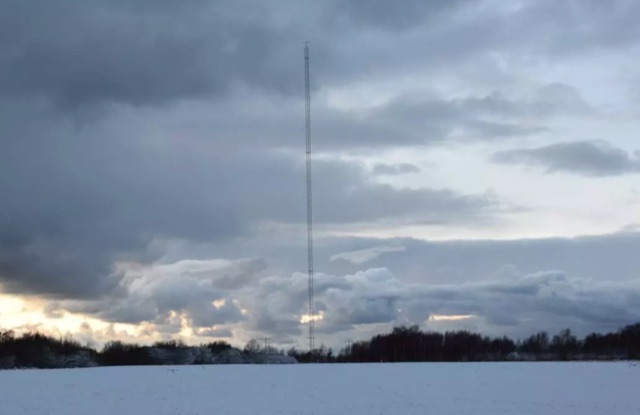 Spitfire Collinear Arrays for 160 meters band at UA2FW
 -
 This type of antenna is a popular antenna design as the performance is very good across the HF bands and requires little or no tuning. It’s a dipole fed off center with a 4:1 balun at the offset feed point. The antenna shown covers 80, 40, 20 and 10 meters. The formula can also be used to adjust the overall length to cover more or fewer bands and the resulting overall length. 160-10m, 80-10m or 40-10 meters depending on your available space. Other bands will require a tuner.
 -
 A 60-foot available space, for example, might necessitate a shortened multiband dipole array to cover 80, 40, and 15 meters effectively. This resource details the construction of such an antenna, combining full-size and coil-loaded dipoles on a single feedline. It addresses the common challenge of fitting multiple HF bands into restricted physical footprints, providing practical guidance for hams with smaller backyards or portable operations. The core of the offering is an interactive calculator that determines required loading coil inductance and dipole lengths for various amateur bands from 160m to 10m. Users input their available space, and the tool provides dimensions, coil turns, and an efficiency rating (Good or Fair) based on the antenna's electrical length relative to a quarter-wavelength. It also suggests suitable _PVC_ pipe diameters for coil forms. The article further illustrates a center feed-point assembly using an 18-inch section of 2-inch _PVC_ pipe, detailing eye-bolt spacing and coaxial connector installation. It emphasizes the importance of adequate spacing between parallel dipoles and offers customization options for the feed-point, including the addition of a _Balun_ for improved feedline isolation.
 -
 WebSDR Pardinho SP Brazil providing access to HF bands 160 80 40 20 15 11 meters bands.
 -
 A vertical antenna for 160 meters band based on the K6MM vertical with some enhancements and modifications on the main capacitance hat
 -
 Jeri Ellsworthhas started a video series devoted to building a magnetic loop antenna for the 160- and 80-meter bands. The first video, included after the break, is an overview of the rationale behind a magnetic loop
 -
 Experimentin wire antennas on top band using several type of aerials. This includes a 40 to 160 meters EndFed Half Wave kite antennas and 160m/80m loaded vertical antenna.
 -
 This antenna is designed for 40, 80 and 160 meters to complement a tri-band beam normally taken on DX peditions for 10, 15 and 20 meters, so six bands can be worked with only two antennas.
 -
 Presents a detailed construction guide for a 9 dB, 70cm collinear antenna, utilizing readily available _RG58/U_ coaxial cable and PVC pipe for housing. The resource outlines the critical calculations for ½ wavelength sections at 444 MHz, incorporating the coaxial cable's velocity factor of 0.66, which yields a section length of 223 millimeters. It specifies the preparation and soldering of eight such half-wavelength sections, each cut to 231mm to allow for trimming, forming the core of the array. Further instructions detail the integration of a ¼ wave element (169mm #16 solid wire) at the top and a ¼ wave aluminum tube (160mm, 5/16 inch) at the bottom, crimped to the feed point's braid. The guide also addresses RF common mode current suppression by suggesting the use of _FT50-43_ toroids on the feedline. Final assembly steps cover mounting the antenna within ¾" PVC pipe using a wooden dowel, waterproofing connections, and initial SWR checks. The article also discusses scaling the design for different element counts and other VHF/UHF bands.
 -
 Steve Nichols, G0KYA, presents a practical examination of ground systems for vertical antennas, drawing heavily on the empirical research of Rudy Severns, N6LF. He explains that a robust radial field is crucial for ground-dependent verticals, effectively replacing the antenna's "missing half" and mitigating severe RF absorption in lossy soil. Nichols clarifies that surface radials do not strictly require a quarter-wavelength; instead, deploying a minimum of 16 to 32 shorter wires often yields superior results compared to fewer, longer ones. The presentation also addresses the common SWR paradox: a poor ground might show a perfect 1:1 match, but adding radials, while potentially raising the SWR to around 1.4:1, significantly improves true radiation efficiency. Nichols defines counterpoises as elevated wire networks that substitute for earth connections, offering solutions for limited-space installations, such as the **Folded Counterpoise (FCP)** for 160 meters. This resource provides actionable engineering data for optimizing vertical antenna performance.
 -
 Documents the A35EU DXpedition to Tonga, specifically targeting the _IOTA OC-049_ Tongatapu group during 2018. The resource outlines the operational bands from 10 to 160 meters and the primary modes utilized, including _CW_, _SSB_, RTTY, and FT8. It provides essential information for DXers interested in confirming contacts with this rare entity, detailing the logistical aspects of the operation and the specific island group activated. This page serves as an archive for the A35EU operation, offering QSL update information and confirming that all log queries were processed and a fresh log uploaded to _Clublog_. Such details are crucial for operators seeking to verify their contacts and apply for awards like DXCC or IOTA, providing a definitive record of the expedition's activity and post-operation administrative status.
 -
 Discover the best low band receive antennas for hams with limited space. Learn about the K9AY loop antenna and Shared Apex Loop Array, two alternatives to the traditional Beverage antenna. Understand the concept of Relative Directivity Factor (RDF) and compare the performance of different receive antennas. See how the Shared Apex Loop, patented by Mark Bauman (KB7GF), offers an RDF between 8 and 10dB. Find out how to optimize antenna performance and enhance your receive capabilities on 160, 80, and 40 meters. Explore the world of low band receive antennas with insights from WB5NHL Ham Radio.
 -
 The quarter-wave Marconi working against ground is a popular and inexpensive antenna for 160 meters. A lot of newcomers to the band favor this simple antenna because it's easy to put up, it isn't too big, and it works.
 -
 DX Pedition to Galapagos will be active from October 26th to November 7th, from 6 to 160 meters (including Warc bands) on CW, SSB and Digi modes with at least 4 stations on the air at the same time.
 -
 Learn how an experienced ham radio operator rebuilt his trap dipole antenna for 30, 40, and 80 meters after a storm damage. Discover the process of upgrading to a short trap dipole for 40, 80, and 160 meters using double-wound traps made from RG-58 coax. Follow along for construction details and tips on building this unique classi.
 -
 A multi-band trapped dipole antenna working on 20, 40, 75 and 160 meters band. This project implement a 20 meter trap unadilla reyco KW-20, 40 meter trap Unadilla Reyco KW-40 and a HI-Q 1:1 balun feed.
 -
 Discover how to easily listen to amateur radio bands with insights from Frank SWL, an experienced radio enthusiast. This guide covers essential tips for tuning into frequencies between 10 meters and 160 meters using modern tools like Web SDR and Kiwi SDR. Learn about identifying callsigns, understanding Q codes, and optimizing your antenna setup for better reception. Whether you're a beginner or an experienced listener, this article provides practical advice for enhancing your radio listening experience in 2025.
 -
 The article by Guy Olinger, K2AV, published in the May/June 2012 National Contest Journal, introduces the Folded Counterpoise (FCP), a compact 516-foot single-wire counterpoise elevated at 8 feet, designed for 160-meter operations on small lots like 100x150-foot backyards. Originating from efforts to revive Top Band for W0UCE on a postage-stamp property, the FCP uses strategic folds to cancel ground fields within 33 feet of center, minimizing losses to 0.13-0.53 dB—outperforming sparse or on-ground radials by up to 15 dB in poor soil—while mimicking opposed radials for efficient feedpoint impedance. Paired with a critical 1:1 or 4:1 isolation transformer (e.g., trifilar on T300-2 toroid) to block common-mode currents on coax feeds, it delivers proven results: K2AV's #8 North America low-power contest score, 7+ dB gains at W4KAZ and K5AF, and over 10,000 global web hits for DIY instructions using bare 12 AWG wire and weatherproof enclosures. Ideal for acreage-challenged hams, the FCP also excels on 80 meters with scaled dimensions, offering a low-loss alternative where full radials are impractical
 -
 Come learn why it is very difficult to predict propagation on the top band. Ionospheric Variability, Time Variations of Ionospheric Parameters, Atmospheric Gravity Waves, Ionospheric Absorption and The Role of Negative Ions.
 -
 The St Paul Island CY9C DXpedition is scheduled for August 26, September 5, 2024. All bands from 160-6 meters are planned.
 -
 This resource presents a non-rigorous evaluation of the front-to-back (F/B) ratio of short Beverage antennas, specifically designed for low-band operation on frequencies such as 160, 80, 40, and 30 meters. The author, VE1ZAC, details the methodology used to measure the F/B ratio, which involves using a Millen Grid Dip Oscillator as a portable signal source. Measurements were taken by switching the antenna direction and recording S Meter and preamp readings to derive gain numbers. The document discusses the challenges faced in achieving accurate measurements and the assumptions made during the process, such as the calibration of S Meter units at 6 dB. This evaluation is particularly relevant for amateur radio operators interested in antenna performance on low bands.
 -
 Demonstrates the construction of an active loop converter specifically designed for the Low Frequency (LF) bands, addressing common localized noise interference in LF reception. The design integrates a sharply tuned circuit and a tuned loop antenna, utilizing the loop as the sole tuned inductive element. By applying positive feedback, the converter significantly increases the loop's effective Q, achieving factors between 1000 and 2000, which sharpens tuning and reduces noise. The circuit employs an _NE602_ mixer stage, feeding its output to an HF receiver, with a crystal-locked local oscillator at 4 MHz. A 20-turn, 0.8-meter square loop antenna with 500 uH inductance is detailed, connected via 2 meters of figure 8 flex cable. The converter offers three selectable frequency bands: 195-490 kHz, 150-220 kHz (including the New Zealand amateur band), and 128-160 kHz (covering the European amateur band). Performance measurements indicate an effective 3dB bandwidth of approximately 100 to 200 hertz at 200 kHz. The article provides insights into component selection, including an _LF353_ op-amp and a trifilar wound transformer on a ferrite core. Sensitivity figures are presented, showing 7.5 uV of converted output per 1 uV/meter signal strength into a 50-ohm load, or 37.5 uV into an _FRG7_ receiver, highlighting its capability to extract weak signals from noise.