Search results
Query: 80 m band
Links: 336 | Categories: 5
-
 A 40 ft vertical dipole antenna that can cover HF Bands from 80 to 10 meters winding a dipole in a 12m HD telescoping fiberglass pole
 -
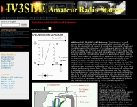
 An article on TX and RX antennae for the low bands 80 and 160m by EI7BA
 -
 Homebrew a vertical antenna for 40 and 80 meters band based on popular HF2V model by DL7JV
 -
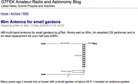 A 46ft multi-band antenna for small gardens that works on 80m. An excellent DX performer and is an ideal replacement for your half size G5RV by G7FEK
 -
 A vertical antenna for 40 and 80 meters band with no need of antenna tuner, based on a telescopic fiberglass mast of 48 feet by N8NSN
 -
 Presents the design and construction of the OK2FJ Bigatas, a portable, automatically tuned vertical antenna covering 80 through 10 meters. It details two distinct control systems: one utilizing BCD band data from Yaesu FT-857/897 transceivers, and another employing voltage level sensing for the Yaesu FT-817. The resource provides specific instructions for building the antenna's radiating element, loading coil with switchable taps, and the control circuitry, emphasizing the use of readily available components. The article outlines the physical construction of the antenna, including the use of duralumin tubes for the radiator and a PVC tube for the coil form. It specifies coil winding details, tap points, and the integration of radial wires for ground plane operation. The control electronics section provides schematics and component lists for both the BCD decoder (using a 74LS42 IC) and the voltage comparator (using an _LM3914_ bargraph driver), enabling rapid, automatic band switching without the minute-long tuning delays common in other systems. Crucially, the antenna achieves rapid band changes, with typical SWR values centered on common operating segments, such as **3.7 MHz** for 80m SSB. It also discusses modifications for CW operation on 80m and the trade-offs between antenna efficiency and full-range automatic tuning on higher HF bands, where manual adjustment of radiator length is suggested for optimal performance on 15m, 12m, and 10m. The resource includes construction photos and a discussion of cable requirements for reliable operation.
 -
 JJ0DRC's HF multi-band delta loop antenna project, initially conceived during the waning peak of Cycle 23, addresses the common challenge of achieving effective DX operation from a small residential lot in Japan. Dissatisfied with a ground plane antenna's performance in SSB pile-ups, the author sought a beam-like solution without a tower, drawing inspiration from a JJ1VKL article in CQ Ham Radio Sep. 2000. The antenna, constructed in October 2000, employs two 7.2-meter fishing rods (37% carbon fiber, reinforced with cyano-acrylate glue and aluminum tape) and 1mm enameled wire, fed by an Icom AH-4 external antenna tuner. While the exact beam pattern remains unmeasured, JJ0DRC observed a significantly higher callback rate compared to dipole antennas, particularly on higher bands. The system's circumference length of 15-20m is crucial for maintaining a good beam pattern across HF bands, though performance on lower bands like 80m, 40m, and 30m becomes less directional as the length deviates from a full wavelength. Ongoing maintenance addressed degradation issues, including aluminum tape cracking and wire breakage at connection points due to strong winds (often exceeding 10-15m/s in winter). The author reinforced rod connections with IRECTOR PIPE SYSTEM components and INSU-ROCK ties, and improved wire attachment methods using Cremona rope and epoxy bond to enhance durability.
 -
 A ranking of receiving antennas based on noise being evenly distributed in all directions. These rankings are most accurate in the frequency range of AM broadcast, 160 or 80 meter bands
 -
 A multiband antenna that can work from 80 to 10 meters in this illustrated docuemnt by G8ODE
 -
 3 Band vertical Marconi-antenna for the bands 40, 80, 160 meters with a ground net of wires as radials.
 -
 An easy to build single wire antenna for 160 and 80 meters with a better than 2 to 1 swr across the 80 meter band
 -
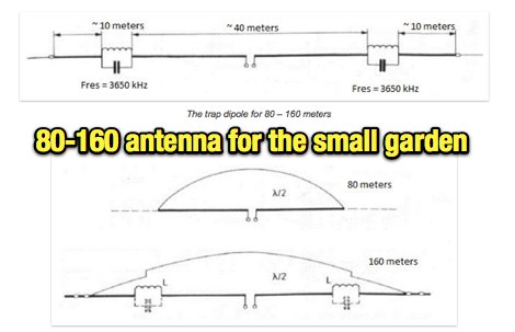
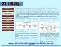 A W3DZZ trapped dipole for 80 40 and 20 meters band by ZL1BJQ
 -
 A three-frequency multi-band dipole that can be extended easily to additional bands. This article includes a multiband fan-dipole antenna for 80-40-20-10 meter band.
 -
 This is a popular antenna design as the performance is very good across the HF bands and requires little or no tuning. It is a dipole fed off center with a 4:1 current balun at the offset feedpoint. The antenna shown covers 80, 40, 20 and 10 meters with 15 meters and WARC bands
 -
 An home made trapped dipole antenna for 40 and 60 meters band by 2E0HTS
 -
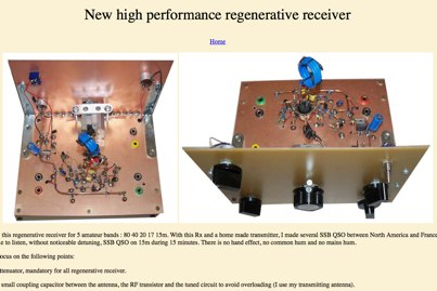 Regenerative receiver for 5 amateur bands : 80 40 20 17 15m by F5LVG
 -
 Multiband no trap no gap antenna. This Antenna is a small wonder, easy to build and allow you to work all HF spectrum with your TRX and it's internal ATU.
 -
-
 An 87ft inverted L portable antenna working on 80 40 30 20 15 meters band
 -
 Operating a ZS6BKW antenna often involves understanding its lineage from the _G5RV_ design, with specific modifications by ZS6BKW to optimize performance on several bands. Through computational analysis and field measurements, the antenna's dimensions were refined to allow operation on 10, 12, 17, 20, and 40 meters without an antenna tuner. For 80, 30, and 15 meters, a tuner is necessary, though efficiency on 30 and 15 meters is noted as not particularly high. The physical configuration consists of two 13.755-meter radiating elements fed by a 12.20-meter section of 450-ohm ladder line. Tuning the antenna on the 20-meter band is critical, and any deviation in the ladder line's characteristic impedance necessitates recalculating the element lengths. The design is also referenced in the 12th edition of _Rothammel's Antennenbuch_, page 219. Proper common mode current suppression is crucial at the transition from ladder line to coaxial cable. This can be achieved with a common mode choke, such as several turns of coax wound into a coil or over a ferrite toroid like an Amidon T130. While a 1:1 balun is an option, it may introduce issues.
 -
 A 90-foot vertical antenna constructed from **aluminum irrigation tubing** is detailed, focusing on its innovative raising and lowering mechanism. The resource describes a **45-foot ginpole** system, allowing a single operator to erect or lower the antenna in minutes. It covers the mechanical design, including the pivot base, insulated joints for the tubing sections, and guy wire attachment points. The antenna consists of two 30-foot sections of 4-inch tubing and one 30-foot section of 2-inch tubing, stacked with the smaller diameter at the top. The electrical design incorporates PVC "condulet" boxes at the 30-foot and 60-foot points, housing relays to change the effective height for multi-band operation on 160, 80, 40, and 30 meters. Ferrite rod inductive chokes are used for DC control and to tune out gap capacitance. The antenna is fed with 1000 feet of open wire line, connected to a matching transformer comprising stacked toroids and a coaxial/toroidal balun. Grounding is achieved with a 3x3 foot grid of 16-gauge tinned copper wires with soldered crossovers.
 -
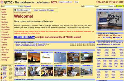 QRZCQ.com provides a centralized online platform for amateur radio operators, integrating a global callsign database with DX Cluster functionality. The service features real-time DX spotting, filtering capabilities for specific bands (e.g., 160m, 80m, 40m, 20m, 15m, 10m), and specialized filters for awards like IOTA, SOTA, WWFF, and QRP activity. It also includes a logbook, QSL manager lookup, contest calendar, and various ham radio articles and news feeds, supporting a wide range of operating activities and information retrieval. The platform aggregates data from multiple sources, offering a dynamic view of on-air activity and callsign information. Users can register for free to access additional services, including a personal logbook, buddy lists, and chat features, fostering community interaction among over 198,600 registered users. The DX Cluster displays recent spots with frequency, DX call, spotter, and remarks, covering bands from VLF to VHF. Beyond DX spotting, the site provides resources such as repeater directories, propagation information, and a swapmeet, making it a multi-faceted tool for both casual browsing and serious DXing or contesting. The service also highlights active users, latest news, articles, and videos, keeping the content fresh and relevant.
 -
 An cheap, easy to construct and not too visible antenna for the low bands
 -
 This resource details the conversion of an 80m elevated vertical antenna to include 160m operation, focusing on a relay-switched design over a trap-based approach. It presents specific feedpoint impedance values, such as **32 ohms** for 80m and **14 ohms** for 160m, and discusses the challenges of SWR drift encountered with the prior trap system during RTTY contesting. The article thoroughly explains the design choices for elevated radials, referencing _N6LF QEX data_ to debunk common myths regarding radial length and height, demonstrating that non-resonant radials can offer superior current uniformity. The construction section provides practical insights into building the vertical, including guying strategies, material selection from scrap pipe, and weatherproofing the relay assembly. It highlights the use of a common mode choke for the relay switching line, measuring approximately 5K ohms on both 160m and 80m, and details the L/C matching network's role in achieving a 50-ohm match at the end of a 300-foot RG-11 run. The author describes a precise VNA-based radial trimming procedure, achieving resonant values within a 3 KHz range. The content emphasizes the practical application of theoretical antenna principles, particularly concerning the interaction between the vertical element, cap hats, and the matching network. It offers a candid assessment of component selection, such as using junkbox parts and acknowledging the need for future upgrades to static drain resistors. The article serves as a comprehensive case study for advanced antenna builders tackling multi-band vertical designs.
 -
 One specific challenge in the KazShack, operating Single Operator Two Radios (SO2R), involved sharing a K9AY receive antenna between two transceivers without direct RF connection or manual feedline swapping. The solution, detailed in this project, adapts the **W3LPL RX bandpass filter** design to split 160m and 80m signals, feeding them to separate radio inputs while maintaining isolation. This approach also addresses the issue of strong broadcast band interference from a nearby 50KW WPTF transmitter on 680kc. The construction utilizes T-50-3 toroids and NP0 ceramic capacitors, built in a "dead bug" style on copper clad board. Each band's filter coils are identical and resonated to the desired frequency using an MFJ-259 antenna analyzer. A single DPDT relay, controlled by a remote toggle switch mounted on an aluminum panel, facilitates quick band switching between radios, simplifying low-band operations. While some signal loss is noted, the expected lower noise levels from the receive antenna are anticipated to compensate, potentially reducing the need for constant volume adjustments during toggling between transmit and receive antennas.
 -
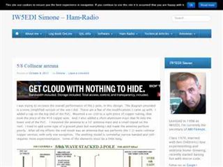
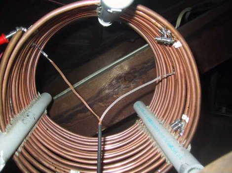
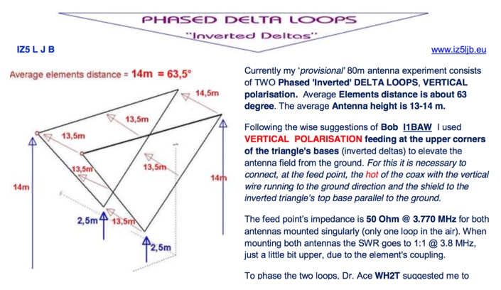 An interesting article with many technical details on a phased delta loop array for 80 meters band includes pictures of antenna relays
 -
 A simple 7 bands off-center dipole wire antenna designed to work on 80 meters band and that can cover also 40m 30m 20m 15m 12m 10m with acceptable SWR
 -
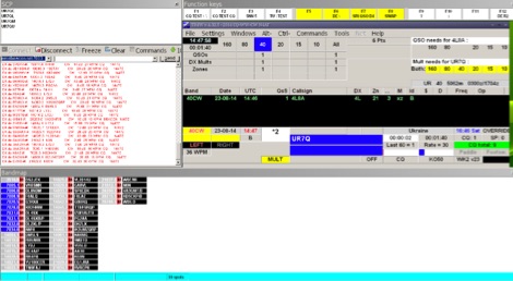 TR4W is a contest logging software package supporting over **180** amateur radio contests. The program operates on Windows 7 to windows 11 operating systems. It supports CW keying via serial port, LPT port, or Winkey, with CW speeds ranging from 1 to **99** WPM. Paddle input via LPT port enables the program to function as a keyer, with paddle input aborting computer-generated CW. PTT support includes programmable delay. The software incorporates automatic super check partial and call checking, along with an expanded .DTA database format for names, QTH, grid, and SS check information. A band map displays color-coded aging data. The software features a built-in telnet DXCluster interface, automatically inserting spots into the band map. It supports RTTY operation via the MMTTY engine and includes WAE QTC support for both European and non-European stations. TR4W provides radio interfacing for Elecraft, Icom, Japan Radio, Kenwood, Ten-Tec, and Yaesu transceivers, utilizing serial or USB-to-serial adapters. Networked multiple-rig operation is supported through a client-server model using TCP/IP protocol. Integrated two-radio support (SO2R) is present. The program includes on-the-fly MP3 recording and log backup to USB drives or selected HDD folders. It uses the standard CTY.DAT file for country and beam heading data.
 -

-
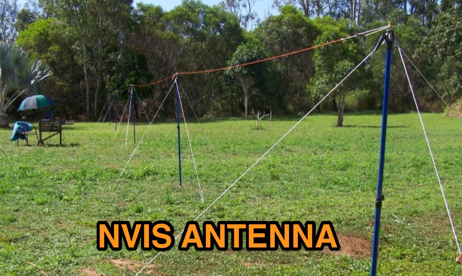 How to homebrew a ENVIS antenna for 80 and 40 meters band
 -
 The ZS6BKW antenna, a popular multiband wire antenna, offers improved band matching compared to the traditional G5RV. This construction guide details the process, beginning with specific dimensions: 13.11 meters (43 feet) for the 450-ohm ladder line and initial dipole arm lengths of approximately 14.8 meters each. It emphasizes the critical role of an _antenna analyzer_ for accurate tuning, particularly for determining the velocity factor of the ladder line and achieving a 1:1 impedance match. The article outlines the materials required, including a 1:1 current balun, 450-ohm window line, wire for the dipole arms, and a 50-ohm non-inductive resistor for testing. It provides a step-by-step procedure for cutting the ladder line to its electrical half-wavelength, explaining how to calculate the velocity factor using measured and free-space frequencies. For instance, a measured 50-ohm impedance at 12.54 MHz with a calculated free-space half-wavelength frequency of 11.44 MHz yields a velocity factor of 0.91. Final adjustments involve hoisting the antenna to its operational height and fine-tuning the dipole arm lengths to achieve optimal SWR, specifically targeting 14.200 MHz. The _ZS6BKW_ design is noted for its performance on 80m, 40m, 20m, 10m, and 6m, though it is not optimized for 15m operation. The author, _VK4MDX_, shares practical tips for durable construction using stainless steel wire and cable clamps.
 -
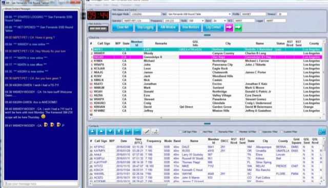 NetLogger displays 6 currently active nets, including the 3838 Breakfast Club on 80 meters SSB and the CornCobNet on 40 meters SSB, providing real-time updates every 20 seconds to monitoring participants. It functions as a specialized logging program designed for amateur radio nets, facilitating the transmission of check-in data via the internet. The system lists net name, frequency, band, mode, server, start time (UTC), elapsed time, number of subscribers, and the callsign of the operator who opened the net. The platform details specific net operations, such as the Florida AM Group on 3.885 MHz AM and the GRAVEYARD NET on 3.967 MHz SSB, illustrating its application across various **HF** bands and modes. NetLogger's utility extends to viewing past nets and offers a **Groups.io** integration for community interaction. It provides a practical solution for organizing and participating in amateur radio nets, offering a centralized system for tracking participants and net activity. The resource details specific net operations, such as the Florida AM Group on 3.885 MHz AM and the GRAVEYARD NET on 3.967 MHz SSB, illustrating its application across various HF bands and modes.
 -
 The Vee Beam antenna project presents a versatile solution for hams, enabling operation across all eight High Frequency bands (80m to 10m) with significant gain on 20m to 10m. This easy-to-construct antenna utilizes two long wires at an angle, enhancing directional performance and minimizing ground losses. With a low visual profile, it is discreet and effective for various applications. The design allows for optimal leg lengths and included angles, ensuring robust performance while maintaining simplicity in construction and operation. The V Beam antenna is an aerial that you can use on all eight High Frequency amateur bands (80, 40, 30, 20, 17, 15, 12 and 10m) with an antenna tuner, and which gives significant gain on the five bands from 20 to 10 meters band.
 -
 An home-brewed morse code CW filter with a central frequency of 800hz and a variable bandwidth from 230hz to 26hz by F5RDH in french.
 -

-

-
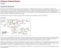 TinySDR for 80m band and ZetaSDR for 40m band
 -
 A lightweight inverted vee antenna that can be supported by a 10 metre long fiberglass squid pole. The antenna is designed to cover 10, 15, 20, 40 and 80 m bands.
 -
 An Off-center-feed antenna that covers 80, 40, 20, 17, 15, 12, 10, and 6 meters
 -
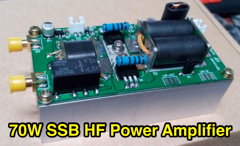 DIY kits a 70W SSB linear Power Amplifier for YAESU FT-817 KX3 running HF 80m-10m bands
 -
 How to build your own beverage antenna for 80-160 meters band by K5ZD
 -
 A simple RF power amplifier initially designed for 40 meter band can work on 10 15 20 40 80 meters
 -
 An attic antenna for 40 and 80 meters band by NS1W
 -
 The G5RV multiband HF antenna, designed by Louis Varney (G5RV) in 1946, is a popular compromise antenna offering good overall performance on most HF bands when paired with an external antenna tuner. The basic full-size G5RV measures 102 feet across the top for 80 through 10 meter operation and is fed at the center via a 34-foot low-loss feed-stub. This interaction between the radiating section and the feed-stub facilitates matching across 80-10 meters with a standard tuner, often eliminating the need for ladder line directly to the shack. The antenna's design center frequency is 14.150 MHz, configured as a 3/2-wave dipole on 20 meters, with its 102-foot length derived from long-wire antenna formulas. Construction details emphasize the matching section, which can be open wire, ladder line (window-type), or TV twin lead. Each type has a specific velocity factor (VF) affecting its physical length for an electrical half-wave on 14 MHz; for instance, open wire requires 33.7 feet (VF 0.97), ladder line 31.3 feet (VF 0.90), and TV twin lead 28.5 feet (VF 0.82). The article provides formulas for calculating these lengths and discusses the antenna's behavior on individual bands, from 3.5 MHz where it acts as a shortened dipole, to 28 MHz where it functions as two three-half-wave long-wire antennas fed in-phase. Practical construction notes include recommendations for vertical descent of the matching section, sealing the coax junction, providing strain relief, and winding a coaxial choke coil to mitigate common mode current. The resource also presents dimensions for double-size (204 ft) and half-size (51 ft) G5RV versions, along with their corresponding matching section lengths for various line types, making it a versatile reference for hams considering this classic wire antenna.
 -
 A 50-ohm 10W resistor forms the core of this portable QRP antenna, designed by _K0EMT_ for convenient operation on 160m and 80m. The construction involves soldering the resistor to a BNC connector, with one lead to ground and the other to the center conductor, then insulating the assembly. This minimalist design aims to provide a highly portable solution for low-band QRP operations, acknowledging the inherent trade-offs between antenna size and efficiency. Testing with an antenna analyzer revealed low SWR on both 160m and 80m, with a Yaesu FT-817 confirming good matching. While 40m and 30m showed higher SWR, the primary focus remains on the lower bands. The author successfully tested the antenna with **2.5W CW** output, demonstrating its practical application for QRP field operations where ease of deployment is paramount, even if it means sacrificing some **gain** compared to full-sized antennas.
 -
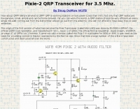 A QRP transceiver for 80 meters band by W1FB
 -
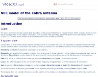 This article explores the Cobra Junior linear loaded antenna for 80m to 10m bands. This antenna is a linear loaded dipole described by W4JOH in 73 magazine June 1997
 -
 An homemade portable trapped dipole antenna for 40 and 80 meters band with an optional extension for the 20 meters.
 -
 DX_Central, a compact desktop application, provides amateur radio operators with critical propagation data by aggregating solar statistics and imagery from various authoritative sources. This includes real-time information from agencies like NOAA and NIST, offering insights into current space weather conditions that directly impact HF propagation. The software is designed for both Linux and Windows operating systems, making it accessible to a broad range of hams. It presents a concise overview of solar activity, which is essential for planning DX operations and understanding band openings and closures across the HF spectrum. Operators can utilize the displayed solar flux index, K-index, and other relevant parameters to make informed decisions regarding their operating times and target bands, optimizing their chances for successful long-distance contacts.
 -
 This article describes a simple Inverted L antenna for the HF bands designed to work on 80m, 40m, 30m and 20m