Search results
Query: coaxial cable antenna
Links: 122 | Categories: 1
Categories
-
 This article describes the construction of a simple dual-band VHF/UHF end-fed vertical dipole antenna designed for local repeater access using an Icom IC-705 radio. Built from a single piece of RG58U coaxial cable, the antenna consists of a 460mm exposed inner conductor, 450mm of intact coax, and a 9-turn choke balun wound on a 27mm former. Mounted on a 10m Spiderpole, the antenna achieves excellent SWR readings (<1.2:1 on 2m, <1.5:1 on 70cm) and provides effective coverage of local repeaters with unexpected reach into distant locations.
 -
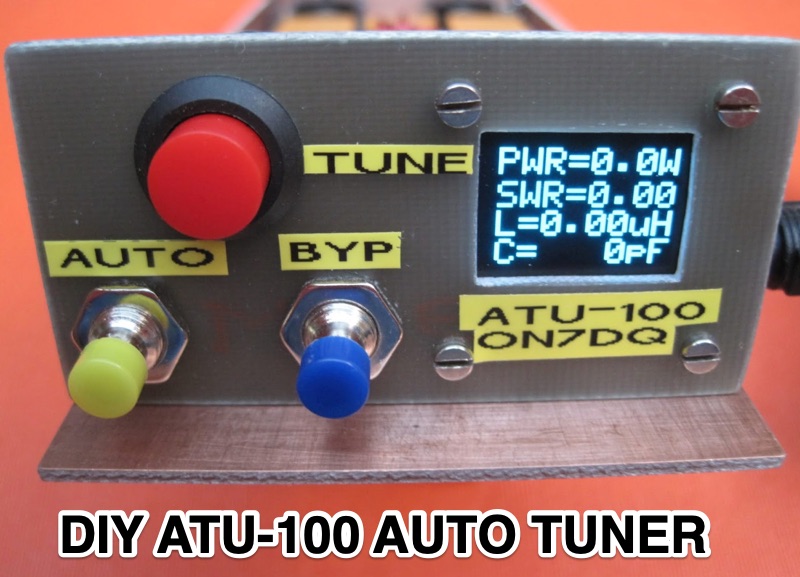 Demonstrates the construction of an **ATU-100 (N7DDC)** automatic antenna tuner, detailing the assembly process from component arrival to final enclosure. The resource covers winding the tandem match transformer, connecting the OLED display, and integrating optional control buttons. Specific attention is given to modifying the EEPROM settings for **QRP operation**, reducing the minimum tuning power to 1 Watt, and addressing potential RF interference with CPU by adding capacitors to button connections. The build log includes practical tips such as adapting RG58 coaxial cable strands for PCB mounting and utilizing a repurposed Macbook Pro cover for the custom enclosure. The author references external GitHub pages for comprehensive information, R0AEK's resources for additional details, and a video by MW0SAW for EEPROM configuration across different ATU-100 variants. Future plans involve field testing the completed tuner during SOTA or other portable activations.
 -
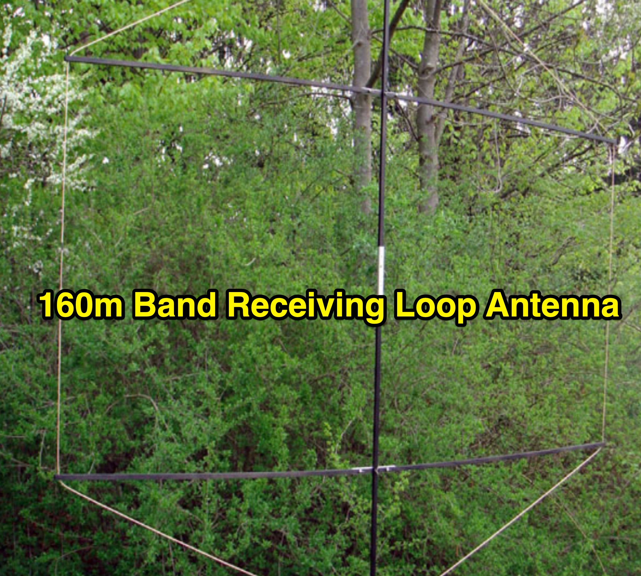 Learn how to build a portable receiving antenna for the 160 meter band. This guide provides detailed instructions on constructing a loop antenna using a coaxial cable RG-316 with SMA connectors. The antenna weighs 1.7 kg and has dimensions of 2m in height and 1.892m in width. The wooden frame consists of four 0.945m long pieces and two 1m long pieces. Perfect for hams looking to enhance their 160m band reception during travel or portable operations.
 -
 This project details the construction of a compact, circularly polarized Quadrifilar Helix Antenna (QHA) designed for 146 MHz operation. The antenna features a 1/2λ1/2λ helical design with a 2.6:1 aspect ratio, providing 4.5 dB gain and a spheroid radiation pattern. It is ground plane independent and compatible with both vertical and horizontal polarizations, making it ideal for terrestrial and space communications. The design includes step-by-step instructions for building the antenna using readily available materials like aluminum rods, PVC pipes, and RG-58 coaxial cable. The antenna's performance has been validated through comparisons with commercial omnidirectional antennas, showing superior results.
 -
 This DIY guide details constructing a 5-element Yagi antenna for VHF frequencies. Yagi antennas offer directional signal transmission/reception compared to omnidirectional ones. The guide covers material selection (aluminum, screws, etc.), design using software or formulas, and step-by-step assembly including cutting elements, drilling holes, and attaching the coaxial cable. While calculations are provided for a 146 MHz design, adjustments are necessary for different frequencies. Safety precautions and potential result variations are emphasized.
 -
 Presents an interactive online **Moxon antenna designer** tool, enabling radio amateurs to configure and analyze lightweight Moxon antennas for HF and VHF bands. Users can specify design frequency, element lengths, wire diameter, insulation, and support height. The tool visualizes the antenna in interactive 3D graphics and generates comprehensive performance charts, including azimuth, elevation, 3D, and polarization radiation patterns, VSWR charts, antenna current diagrams, and Smith charts. It also allows selection of various ground types (e.g., very poor soil, salt water, free space) to model environmental effects on antenna performance. The designer provides insights into how physical dimensions and ground conditions influence key antenna parameters like forward gain, front-to-back ratio, and feed-point impedance, which is typically close to 50 ohms. It also includes a feature to model the effect of coaxial cable losses on **VSWR** at the transmitter end, distinguishing it from the feed-point VSWR. This helps operators understand the actual radiated power efficiency versus the apparent match at the transceiver, offering a practical perspective on antenna system performance in portable operations.
 -
 EA4EOZ details the construction and testing of 50 MHz traps, a critical component for multiband antenna designs. The project addresses the challenge of sourcing high-voltage capacitors suitable for trap applications, exploring alternatives to expensive doorknob capacitors. The author successfully fabricated a capacitor using 1.6mm double-sided FR-4 PCB material, achieving a capacitance density of **2.6 pF/cm2**. Utilizing the _VE6YP calculator_, specific L and C values of 30 pF and 0.31 uH were determined for a 2cm diameter coil. Both the FR-4 PCB trap and a coaxial cable trap, constructed from _RG-58_, were built and tuned to approximately 50 MHz using a spectrum analyzer. The coaxial cable trap demonstrated superior performance, exhibiting a notch nearly **20dB deeper** than the FR-4 version. This practical comparison provides insights into trap construction for experimental antennas, with the coaxial cable trap selected for an antenna project intended for operation at up to 100 watts.
 -
 Constructing a double bazooka antenna for the UHF band, specifically tuned for 435 MHz, involves a straightforward process detailed with step-by-step imagery. The design leverages readily available _RG213 coaxial cable_, cut to precise lengths derived from formulas: 140.208 / F (MHz) for the radiating element and 99.06 / F (MHz) for the coaxial section. This approach yields a highly effective vertical polarization antenna, suitable for local ragchewing or repeater access. My own field experience with similar coaxial designs confirms their robustness and ease of deployment. The article emphasizes critical steps like short-circuiting cable extremities, interrupting the braid at the center, and securing an insulating support. It also covers preparing the definitive mounting with a quality feedline, noting that RG58 is acceptable for temporary use but better options exist for permanent installations. Weatherproofing is crucial for longevity, achieved through PVC electrician's tube, glue, and heat-shrink tubing. The final assembly is designed for mounting on a small aluminum mast, with the feedline routed internally. The reported SWR measurement is very satisfactory, showing approximately **+/- 3%** HF return, indicating excellent impedance matching at the target frequency.
 -
 The resource details the construction of a J-pole vertical antenna specifically engineered for motorcycle mounting, addressing the common issue of interference with top cases. It outlines the fabrication process, beginning with an aluminum angle bracket for secure attachment to the lateral support, followed by the creation of the antenna's base from an 8mm threaded rod bent into a U-shape, approximately **40mm** wide. The article specifies the precise method for coaxial cable connections using eyelets and 3mm screws, ensuring robust contact. Further construction steps involve fitting a 10mm aluminum tube onto the threaded rod, with a screw securing the radiating element and establishing core contact. The design prioritizes mechanical stability against vehicle vibrations over fine-tuning SWR with sliding collars. Initial testing yielded a _SWR_ of **1.2** across a significant portion of the band, with improvements noted by optimizing the coaxial braid contact point near the support bracket. The document provides practical insights into material selection and assembly, emphasizing durability for mobile operation. It concludes with aesthetic options, allowing the builder to paint the antenna or retain its natural aluminum finish, making it a functional and adaptable solution for UHF motorcycle communications.
 -
 The Dipole Bazooka Antenna for 40 meters is a popular choice among amateur radio operators. Its design allows for easy construction using materials like RG58 coaxial cable and PVC. Measurements are calculated using specific formulas; for instance, at a frequency of 7,100 MHz, the total length is approximately 19.74 meters. This antenna offers a performance range of 97% to 99%, with an impedance of 49 to 52 ohms. Additionally, it can handle up to 1 kW of power and requires no modifications for connection.
 -
 This resource details the construction and performance of a compact broadband magnetic loop antenna designed for portable receiving applications with devices like the _ATS MiniRadio_. The antenna utilizes approximately 3 meters of 0.5–1 mm copper wire wound in two turns on a rhomboidal wooden frame, measuring 50 cm by 70 cm. It connects via a modified 9:1 unun, where the primary center tap is isolated from ground to improve common-mode noise rejection. The design provides untuned operation across a frequency range from the longwave band up to approximately 25 MHz. Performance characteristics include observable directivity for noise suppression and the ability to connect directly to a radio or via a 50 coaxial cable for remote operation. The article specifies the unun's 3:1 turns ratio and its SMA output for connectivity. The methodology focuses on practical construction and observed reception quality.
 -
 Addresses the common challenge of constructing effective dual-band antennas for VHF/UHF operations, specifically detailing a J-pole design. It covers the theoretical underpinnings, including calculations for quarter-wavelength radiator and stub sections, accounting for velocity factor and design frequency. The resource provides practical construction guidance using readily available materials like TV twin lead and coaxial cable, culminating in an antenna with a total length of approximately 52 inches. Performance metrics are presented, showing a measured SWR of 1.7:1 or better across most of the 2-meter band and less than 2:1 across the 70-cm band. These SWR measurements, referenced to 50-ohm impedance, were taken at the transmitter end of the feed line. The article also touches upon the necessity of a balun for proper impedance matching between the balanced J-pole and unbalanced coaxial feed line, suggesting a split-core cylindrical ferrite for this purpose.
 -
 Volda is specialized in telecom tower antenna line accessories such as cable hangers, coaxial jumpers, grounding buss bar kits, pole clamps.
 -
 Details the installation and operation of the DX Engineering TFS Series Transmit Four Square System Phasing Units, specifically models like the DXE-TFS4-160B, DXE-TFS4-80B, and DXE-TFS4-40B. It covers system components, required parts, and a discussion of vertical antenna selection, including a table of suitable DX Engineering Monoband Vertical Antennas. Installation procedures are outlined, encompassing site selection, four square layout, topographical considerations, and noise source mitigation. Specific instructions are provided for mounting the phasing unit, antenna feedline connections using 1/4-wave 75-ohm coaxial cables, and control wire routing. The document also includes details on radial system implementation, with a table of radial wire lengths for 160, 80, 75, and 40 meters, and procedures for tuning the vertical antennas for optimal performance. Operational aspects of the Four Square Control Console are described, including front and rear panel functions, control logic (Table 4), and typical transceiver/amplifier interconnections. The system enables directional control with approximately 5 dB gain over a single vertical element in four directions or an omni-directional pattern, achieving typical front-to-back ratios exceeding 20 dB. Lightning protection and initial system testing are also addressed, along with a 5 kW CW and 10 kW PEP SSB power rating and hot switching lockout feature.
 -
 Presents the design and construction of a folding 5-element Yagi antenna specifically engineered for 144 MHz portable operation, particularly for VHF contest Rover categories. It details element dimensions, boom construction using ¾-inch pine, and a folding mechanism that reduces the 52-inch boom to 26 inches for transport. The document provides a table with precise element distances and lengths, including a 2.4 mm length correction for solid parasitic elements, and specifies the use of 3/16-inch solid aluminum for parasitic elements and brass tubing for the driven element. It also covers the bent dipole driven element design for impedance matching, balun implementation with Type 31 ferrite beads for common mode current suppression, and weatherproofing for the feed point. The resource includes predicted performance data from 4NEC2 modeling, showing SWR and return loss characteristics, as well as gain and front-to-back ratios at various frequencies across the 2-meter band. It reports a measured SWR of 1.2:1 at 144.2 MHz and 1.5:1 at 147 MHz, corrected for 25 feet of RG-8/M coaxial cable loss. The design offers approximately 1.5 dB more gain than a previous 4-element design, maintaining a decent SWR up to 147 MHz, and was successfully deployed in a winning June 2016 ARRL VHF Contest Rover entry.
 -
 This article describes the design and construction of a 4-meter band vertical sleeved dipole antenna, built to complement a newly acquired Yaesu FTDX10 transceiver. The simple yet effective antenna consists of modified coaxial cable housed in weather-resistant plastic conduit, featuring an integrated 8-turn choke coil. Despite common misidentification as an EFHW antenna, this design is actually a sleeved dipole that provides an excellent 50-ohm match across the band, achieving SWR values between 1:1 and 1.1:1. The project demonstrates an economical approach to entering the relatively quiet 4-meter band.
 -
 The UHF J-Pole antenna described here utilizes an aluminum angle bar and 4mm galvanized threaded rod for its construction, with dimensions based on a previously published design. Assembly involves drilling the angle bar, securing threaded rod sections with nuts, and connecting the coaxial cable via cable lugs, ensuring the braid connects to the shorter element. ROS adjustment is achieved by manipulating nuts approximately **30mm** from the angle bar, allowing for fine-tuning of the impedance match. Once optimal tuning is established, _super glue_ is applied to seal the coaxial cable ends and protect the threaded rod cuts from corrosion, enhancing durability. This project emphasizes rapid realization with common hardware, providing a practical solution for radio amateurs seeking a simple yet effective antenna for the 70cm band.
 -
 Operating amateur radio satellites presents unique challenges, particularly concerning antenna design and signal propagation. Juan Antonio Fernández Montaña, EA4CYQ, recounts his three-year journey into satellite communication, starting with initial guidance from EB4DKA. His early experiments involved a portable 1/4 wave VHF antenna with four 1/4 wave ground planes, designed for hand-held use to adjust polarity. This setup, paired with an FT-3000M transceiver, allowed full-duplex operation on **VHF** transmit and **UHF** receive, proving effective for early contacts on satellites like AO27, UO14, and SO35. EA4CYQ's experience highlights the critical role of coaxial cable loss and antenna polarization. After encountering significant signal degradation with longer RG213 runs, he experimented with a 1/2 inch commercial cable, noting improved reception but persistent fading due to varying satellite polarities. This led to the construction of an **Eggbeater II** antenna, an omnidirectional UHF design offering horizontal polarization at the horizon and circular right polarization at higher elevation angles. Subsequent modifications resulted in the directional **TPM2** antenna, which provided sufficient gain for LEO satellites with a wide 30-degree lobe, enabling consistent contacts from his home station. The article concludes with practical insights on the performance of the Eggbeater II for both UHF and VHF, and the TPM2 for UHF, emphasizing their utility for portable and fixed operations. EA4CYQ's journey underscores the iterative process of antenna development and the importance of adapting designs to overcome real-world propagation challenges in satellite communications.
 -
 Demonstrates a specific impedance matching technique for resistive loads ranging from 22.2 to 45 ohms, connecting them to a 50-ohm transmission line. The method employs series sections of 50-ohm and 75-ohm coaxial cables, with graphical data illustrating the required cable lengths (L1 and L2) in wavelengths for a perfect match. This approach is particularly useful for feeding **vertical** and **Yagi antennas**. The resource provides a practical example of matching a 25-ohm Yagi antenna at 50.150 MHz, specifying the use of RG-58C/U (50 ohms) and RG-59B/U (75 ohms) cables, both with a 66% velocity factor. It calculates the precise physical lengths in centimeters and inches for the required cable sections. Additionally, the document briefly discusses integrating a balun at the load end, suggesting methods such as coiling a cable section or utilizing ferrite beads to create a W2DU-type balun. The presented methodology offers a clear, data-driven solution for common antenna impedance challenges.
 -
 This article explores the role of velocity factor (VF) in calculating stub lengths for VHF/UHF Baluns. It clarifies misconceptions about VF's relevance, distinguishing between coaxial cable interior fields and external stub fields. Practical examples, such as the Pawsey Stub and Coaxial Cable Balun, are analyzed alongside experimental findings. The results reveal that traditional VF adjustments are unnecessary for stubs with external fields but critical for internal coaxial applications. Historical and theoretical insights provide a comprehensive perspective for antenna enthusiasts and designers.
 -
 Presents an online retail platform for amateur radio operators, showcasing a diverse inventory of equipment and accessories. The site lists popular transceivers such as the _Icom IC-7300_ and _Icom IC-7610_, alongside various antenna solutions including base, HT, mobile, and end-fed designs. Operators can find coaxial cable, including bulk options and products from "The Wire Man," essential for shack setup. The platform also stocks crimping and stripping tools, adapters, and power supplies, crucial for station maintenance and construction. Test equipment like _RigExpert Analyzers_ and accessories such as Daiwa meters and _West Mountain Radio_ Power Poles are available. Additionally, the site offers software from _Ham Radio Deluxe_ and _RT Systems_, catering to logging and radio programming needs. Shipping policies include free shipping on C.Crane Radios and most orders over $100.00 within the lower 48 states, providing clear purchasing incentives.
 -
 VE2AZX's 2013 Radio Talk presentation details the technical aspects of baluns, including reasons for their use, various types, and methods for performance verification using an SWR analyzer. The document specifically examines 1:1 voltage baluns and 4:1 voltage baluns, outlining their winding configurations and typical impedance transformations. It presents empirical SWR measurements for W2AU 1:1 baluns and Unadilla 4:1 baluns, tested with both 50-ohm and 200-ohm resistive loads across the HF spectrum. The presentation further explores the measurement of ferrite impedance and their application in mitigating common-mode currents on feeders and household conductors. Key concepts addressed include balanced-to-unbalanced transformation, ensuring feeder independence from the antenna, and reducing unwanted feeder radiation. The content emphasizes practical testing procedures to ensure optimal antenna system performance and minimize RF interference. Discussions also cover open-circuit tests with SWR analyzers and VNAs to assess winding inductance, distributed capacitance, and insulation quality. The presentation differentiates between voltage and current baluns, explaining how current baluns, particularly those utilizing ferrite cores, reduce outer shield currents without affecting internal coaxial cable currents, thereby preserving the antenna's intended radiation pattern.