Search results
Query: eme antennas
Links: 222 | Categories: 2
-
 A detailed guide presents a simple 2-element quad antenna for 2m, offering ease of construction, portability, and efficient performance across the 144-148 MHz band. The design allows quick disassembly for storage and features adjustable polarization, making it ideal for various applications, including transmitter hunting and SSB operations.
 -
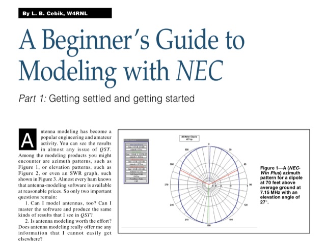 Antenna modeling is an essential technique for both amateur and professional engineers, enabling precise analysis of antenna performance. This guide, published on 4 different QST articles by L. B. Cebik, introduces NEC-2, a widely used public domain software for modeling antennas, focusing on its capabilities and practical applications. The series aims to demystify the modeling process, providing foundational knowledge and techniques for effective antenna design. Key concepts include understanding the method of moments and the importance of segmenting antenna elements. By mastering these principles, users can enhance their comprehension of antenna behavior and optimize their designs for improved performance.
 -
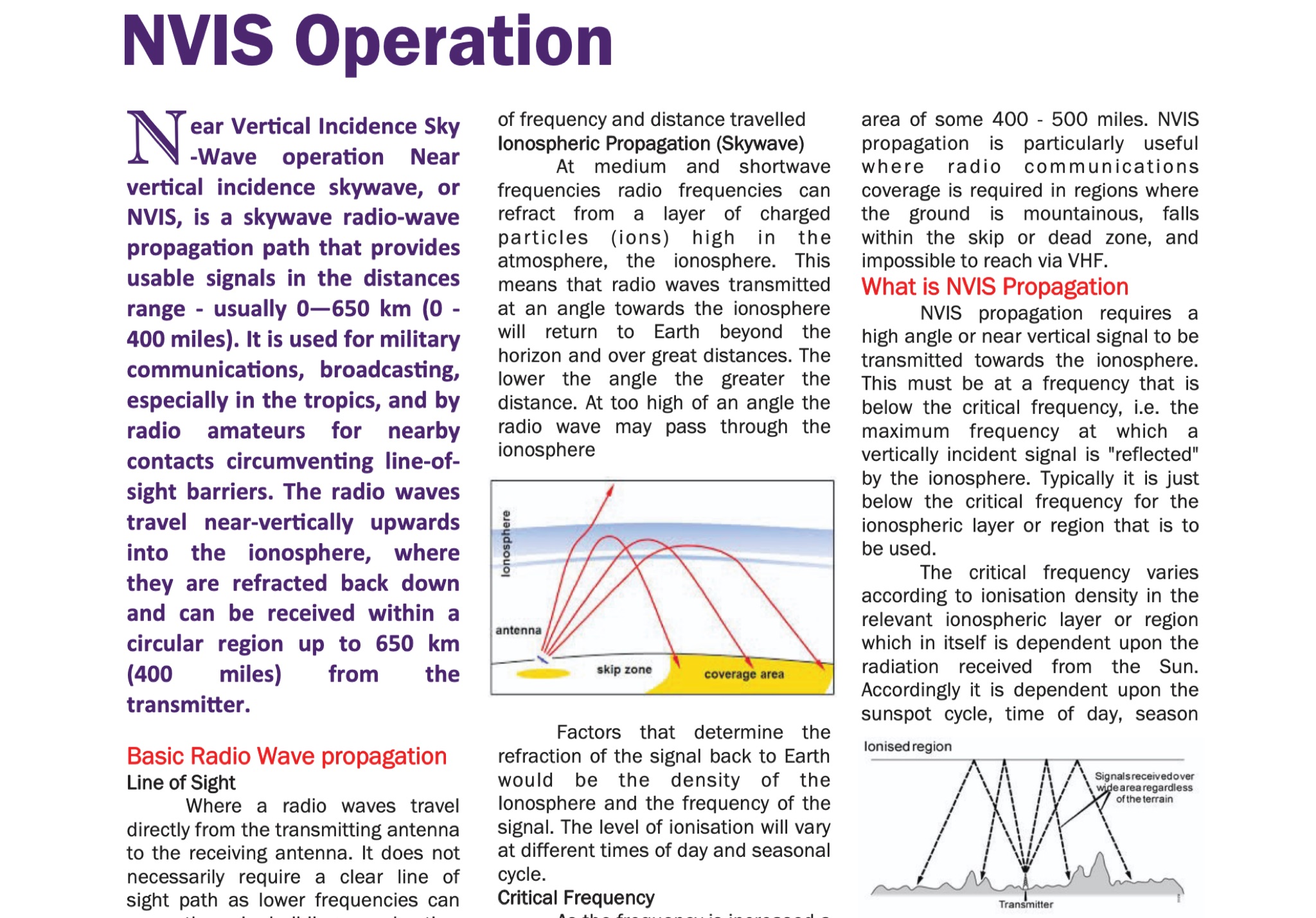 The document provides fundamental information on radio wave propagation and NVIS communication, covering line of sight, surface waves, and ionospheric reflection.<p> It focuses on the Near Vertical Incidence Skywave (NVIS) method for reliable coverage in mountainous or skip zones, especially for regional and emergency communications.
 -
 Integrating a _Software Defined Radio_ (SDR) into an existing ham radio setup involves connecting it with a standard transceiver (TRX), power amplifier (PA), and antennas. The core component is a splitter box that facilitates the connection between the TRX and the SDR, allowing for simultaneous operation without modifying existing equipment. In receive mode, the splitter ties the antenna inputs of both the TRX and a direct conversion receiver (DC RX) together. During transmission, the DC RX input is grounded via a fast telecom relay controlled by the transceiver's -SEND signal, incorporating a 10ms delay for safety. The splitter box includes a 3.7 dB input attenuator for impedance matching and acts as a protective fuse for the DC RX input. Ground loops are mitigated using common mode balun transformers, while the DC RX input is insulated with a broadband transformer. An audio switch box complements the setup, enabling users to listen to either the main transceiver, the SDR output, or both simultaneously. This configuration ensures noise immunity and safety, with the splitter housed in a screened box made from PCB material. On-air tests, such as the CQ WW 160m CW DX Contest, demonstrate the system's effectiveness, showcasing the SDR's ability to handle crowded band conditions with superior selectivity and dynamic range. The SDR's narrow bandwidth filters and waterfall display provide significant advantages, allowing operators to detect weak signals amidst strong interference. The integration of SDR with conventional radios offers enhanced operational flexibility and performance in challenging environments.
 -
 Testing of real antennas is fundamental to antenna theory. The most common and desired measurements are the antenna radiation pattern including antenna gain and efficiency, the impedance or VSWR, the bandwidth, and the polarization. The procedures and equipment used in antenna measurements are described in this page.
 -
 W1JR-style common mode chokes are versatile tools for antenna experimentation. Three variants were constructed using RK4 ferrite cores and RG303 Teflon coax, differing only in output terminals: banana connectors for dipoles, N-connectors for antennas with existing terminals, and bolts with washers for vertical antennas. Materials included junction boxes, terminals, and small hardware. Assembly involves maximizing windings on the core, securing with ties, and gluing components. Improvements included switching to multi-stranded wire for durability. These chokes provide efficient, customizable solutions for various antenna setups.
 -
 This **PDF report** documents a _maritime mobile_ DXpedition operating from the _Southern Ocean_ near Antarctica, detailing antenna deployment strategies on a sailing vessel. It addresses power management systems for remote operations and propagation characteristics specific to polar regions on **20m and 40m** bands. Operational strategies include managing high-density pileups using split frequency operation and maintaining signal integrity during periods of high aurora activity. Equipment considerations cover specific transceiver models like the Icom IC-7300, antenna types optimized for marine vessel installation, and battery power systems for extended periods without shore power. The resource also examines the use of satellite communication for real-time log uploads and QSL confirmation from remote locations, and discusses mitigating signal degradation from ice accumulation on antennas. DXZone Focus: PDF report | Maritime Mobile DXpedition | Polar Propagation | Split Frequency Operation
 -
 The article discusses the evolution of antenna designs, specifically focusing on the upgrade from the W7IUV rotatable Flag to the Waller Flag. Author Pierluigi Mansutti IV3PRK shares insights on modeling these antennas using EZNEC software, detailing their performance in noisy environments. The W7IUV Flag proved effective for receiving signals, while the Waller Flag, developed by NX4D and N4IS, offers improved front-to-back ratios but requires careful consideration of signal levels and noise management. The article emphasizes practical modeling results and interactions between different antenna setups.
 -
 This article from the July 1976 issue of Radio REF discusses the trend of large antennas for ham radio operators on the low bands. It specifically focuses on a Yagi 2 element antenna for the 80m band, detailing its construction and functionality. The author explains how the antenna can be switched between directing signals towards the West or East using a switch at the station. The article also provides technical details on the lengths of the director and reflector elements, and how they impact the antenna's performance. A useful resource for hams looking to build or understand Yagi antennas for the 80m band.
 -
 This article explores the powerful features of AutoEZ as an Excel application working with EZNEC antenna modeling software. The article demonstrates how variables, equations, and formulas enable versatile antenna design and automatic optimization. Through practical examples including dipoles, inverted vees, delta loops, and monopoles, the author shows techniques for achieving resonance, implementing transmission line resonators for broadbanding, and optimizing antennas across frequency ranges. The step-by-step demonstrations cover unit conversion, coordinate calculations, segmentation considerations, and SWR optimization. This practical guide illustrates how AutoEZ extends EZNEC's capabilities, making complex antenna modeling more efficient and accessible.
 -
 Operating on the 60m band requires specialized antennas, and the 2 Element HB9CV, also known as the _ZL special_, excels in this domain. With a gain of **7.3 dBi** when phased at a 162-degree shift, it rivals traditional 3-element Yagi antennas, making it a solid option for enhancing 60m operations. The construction process is thoroughly detailed, providing insights into its performance and practical applications. Real-world comparisons demonstrate that the HB9CV antenna outperforms long Beverage antennas by an average of **5.5 dB** in reception, showcasing its effectiveness in various conditions. Insights from Mr. Cebik's analysis further validate its design, confirming its capability to maximize communication on the 60m band.
 -
 YAGio 1.01 is a Windows-based software for designing DL6WU long Yagi antennas on VHF and UHF frequencies. It supports Windows 2000, XP, Vista, 7, and likely 8. Using keyboard commands, users input specifications such as frequency, gain, and element diameters, and YAGio generates the design. You can download latest Yagio version from this page. Results can be saved in YIO, NEC, YAG, MMA, and YC6 formats, or printed directly.
 -
 Details the construction and performance of a phase-controlled receiving array, specifically a **MicroSWA** variant, optimized for QRP low band fox hunting on 40M and 80M. The resource documents the author's iterative design process, addressing significant regional noise challenges encountered during 0100-0230 UTC fox hunt periods. Initial experiments involved a director wire on a 40M vertical, yielding limited improvement, prompting a shift towards advanced null-steering techniques. The project leverages concepts from Victor Misek’s "The Beverage Antenna Handbook" and Dallas Lankford’s extensive work on phased receiving antennas for urban lots. A key modification involved integrating a new passive phase control box and a push-pull **Norton common base preamp** using 2N5109 transistors, designed for high third-order intercept performance to maintain weak signal integrity amidst strong adjacent signals. The system incorporates Faraday-shielded transformers with RG174 primaries on -75 ferrite cores, housed in ABS plastic pipe. Performance tests confirmed the MicroSWA's ability to produce deep, steerable nulls, achieving approximately 30 dB noise reduction on 160M, 80M, and 40M. This enabled detection of QRP signals undetectable on conventional transmit antennas. The final unit includes front panel controls, a 10-11 dB preamp, and a robust power conditioner, demonstrating effective noise mitigation for challenging low band QRP operations.
 -
 This paper by Leif Asbrink (SM 5 BSZ) presents a practical approach to designing very high gain Yagi antennas, focusing on the "brute force" optimization method. The method, described in a previous article, ensures convergence independent of initial guesses. The paper provides detailed tables of element lengths and positions for Yagi antennas optimized for 144.1 MHz with a 50-ohm feed point impedance, aiming for minimal losses and high accuracy in comparisons.
 -
 145 MHz is the target frequency for this 2-meter Skeleton Slot Yagi Stack antenna project. The design focuses on feeding two stacked Yagi antennas using a skeleton slot radiator, which is a unique approach for VHF enthusiasts. The project details the construction process, including the loop tapered matching section for impedance matching, ensuring optimal performance. The use of specific components like the EH789 element holder and MB456 main mast bracket is highlighted, providing clarity on the assembly process. The construction utilizes 20x20 box aluminum bar for durability and precision. Key dimensions, such as the element length (ER-ED4) and main boom spacing (MM123), are meticulously outlined. This attention to detail aids in replicating the antenna design accurately. The downloadable PDF offers comprehensive instructions, making it accessible for amateur radio operators interested in VHF antenna construction. This project is particularly beneficial for those looking to optimize their 2-meter band operations. The inclusion of a skeleton slot radiator and loop tapered matching section demonstrates advanced techniques in antenna design, catering to both intermediate and advanced builders.
 -
 VE1ZAC's analysis details the performance of **MFJ927** and **SGC239** autotuners with portable HF vertical antennas, specifically comparing 31 ft and 43 ft configurations. The resource originated from challenges encountered during a Maritime QSO Party roving operation, necessitating a lightweight and easily deployable antenna system. Target bands for the contest included 80, 40, 20, 15, and 10 meters, with a maximum power handling of 100 W CW. The author utilized a 30-foot carbon fiber push-up pole to support a vertical wire element, noting its 2 lb weight and reliability. EZNEC modeling was employed to predict performance, showing favorable results for a 30-foot vertical with elevated radials, particularly on 40 and 20 meters. Feedpoint impedance measurements, taken with an AIM4170C, are presented for various HF bands, both with and without a 41-foot RG6 stub designed to reduce reactance on 80 and 20 meters. The stub significantly improved matching on these bands, easing the tuner's workload. Operational tests revealed issues with the MFJ927's reliability during contest setup, leading to reliance on the K3's internal tuner. The SGC239, tested post-contest, performed flawlessly. A detailed side-by-side comparison covers mechanical aspects, connection options, power bias, impedance range, board quality, and documentation. Modifications to the MFJ927, including a new aluminum case, white paint for heat reduction, and upgraded impedance-measuring resistors, are also described.
 -
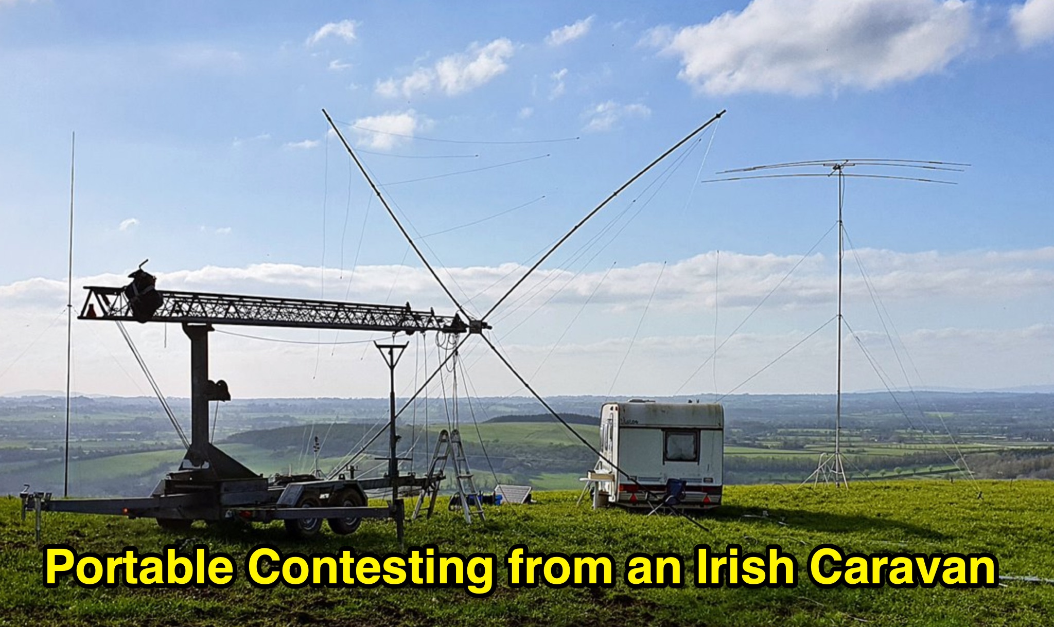 This blog chronicles over a decade of portable HF contesting from rural Ireland (2008–2019) by Olivier, operating under callsigns EI/ON4EI, EI8GQB, EI1A, and EI7T. Using only green energy from a caravan, he achieved top-tier results in major international contests—including 1st World in the 2018 IARU HF Championship (SSB LP) and multiple 1st-place finishes in CQ WW and CQ WPX SSB Europe. Operating in the demanding Single Operator All Band Low Power and SO2R categories, he deployed up to five antennas across five bands, often in remote or emergency-style conditions. The narrative blends technical detail, fieldcraft, and personal reflection, documenting triumphs, setbacks (including carbon monoxide poisoning), and the logistical challenges of sustainable portable operation—culminating in his decision to transition to team-based contesting and future DXpeditions.
 -
 This resource presents a non-rigorous evaluation of the front-to-back (F/B) ratio of short Beverage antennas, specifically designed for low-band operation on frequencies such as 160, 80, 40, and 30 meters. The author, VE1ZAC, details the methodology used to measure the F/B ratio, which involves using a Millen Grid Dip Oscillator as a portable signal source. Measurements were taken by switching the antenna direction and recording S Meter and preamp readings to derive gain numbers. The document discusses the challenges faced in achieving accurate measurements and the assumptions made during the process, such as the calibration of S Meter units at 6 dB. This evaluation is particularly relevant for amateur radio operators interested in antenna performance on low bands.
 -
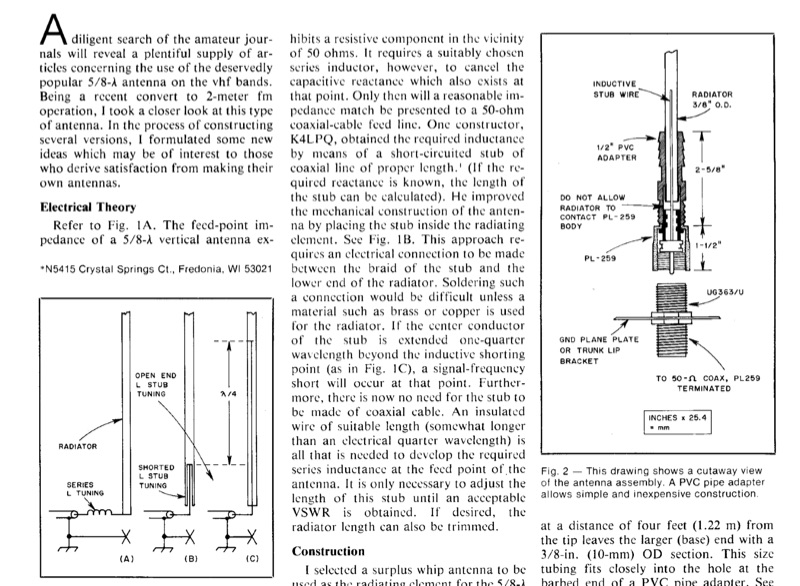 A 5/8-wavelength vertical antenna for 2-meter FM operation is detailed, focusing on eliminating loading coils by utilizing a series inductor to cancel capacitive reactance at the feed point, thereby presenting a 50-ohm impedance match. The design illustrates three basic configurations, including a method employing a short-circuited coaxial stub for inductance, as implemented by K4LPQ. An alternative design is presented where the center conductor of the stub is extended one-quarter wavelength, creating a signal-frequency short and allowing for an insulated wire stub to develop the required series inductance. The article provides electrical theory and mechanical considerations for building the antenna, emphasizing the adjustment of stub length for proper impedance matching. This technical documentation is intended for amateur radio operators interested in homebrewing VHF antennas, offering practical insights into impedance matching techniques for vertical radiators.
 -
 The article describes adding lightning protection to Beverage antennas, which are long wires susceptible to lightning strikes. The author reviews common lightning protection circuits and discusses their components. They then detail their design based on existing methods, highlighting choices for components and reasoning behind them. Finally, the author presents the completed design and its implementation on their Beverage antennas.
 -
 SAT filters ensure effective full-duplex satellite QSOs by mitigating interference between 145 MHz uplink and 435 MHz downlink signals. Custom coaxial and SMD-based filters address transmitter harmonic interference and improve receiver isolation, achieving over 70 dB suppression in the undesired band. Designed for simplicity, these filters maintain optimal VSWR and are housed in shielded brass enclosures. Practical implementations with Yagi antennas demonstrate compatibility with SDR systems, enabling seamless communication even in challenging satellite conditions, such as low-elevation passes and DX pile-ups.
 -
 Demonstrates the construction of an active loop converter specifically designed for the Low Frequency (LF) bands, addressing common localized noise interference in LF reception. The design integrates a sharply tuned circuit and a tuned loop antenna, utilizing the loop as the sole tuned inductive element. By applying positive feedback, the converter significantly increases the loop's effective Q, achieving factors between 1000 and 2000, which sharpens tuning and reduces noise. The circuit employs an _NE602_ mixer stage, feeding its output to an HF receiver, with a crystal-locked local oscillator at 4 MHz. A 20-turn, 0.8-meter square loop antenna with 500 uH inductance is detailed, connected via 2 meters of figure 8 flex cable. The converter offers three selectable frequency bands: 195-490 kHz, 150-220 kHz (including the New Zealand amateur band), and 128-160 kHz (covering the European amateur band). Performance measurements indicate an effective 3dB bandwidth of approximately 100 to 200 hertz at 200 kHz. The article provides insights into component selection, including an _LF353_ op-amp and a trifilar wound transformer on a ferrite core. Sensitivity figures are presented, showing 7.5 uV of converted output per 1 uV/meter signal strength into a 50-ohm load, or 37.5 uV into an _FRG7_ receiver, highlighting its capability to extract weak signals from noise.