Search results
Query: lf antenna
Links: 317 | Categories: 5
-
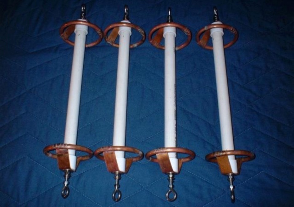 Homebrewing special insulators with PVC and copper corona rings
 -
 KB6NU end-fed, half-wave antenna article and project
 -
 Constructing a compact directional antenna for the 17-meter band, this resource details the build process for a Moxon rectangle, a two-element Yagi variant with folded-back elements. It covers the antenna's evolution from the _VK2ABQ beam_ and provides specific dimensions for a version built using fishing pole whips. The content includes a discussion of the antenna's radiation pattern, feedpoint impedance, and its inherent front-to-back ratio, which is often superior to a standard two-element Yagi. Practical considerations for element spacing and material choices are also addressed, alongside a visual representation of the antenna's physical layout. Performance data presented includes a comparison showing the Moxon rectangle's **2.5 dB gain** over a half-wave dipole and a front-to-back ratio of **20 dB**. The resource also touches upon the antenna's relatively wide bandwidth for a two-element beam and its suitability for portable operations due to its compact footprint. It offers insights into optimizing the design for specific operating conditions and discusses the advantages of its lower take-off angle compared to omnidirectional wire antennas, making it effective for DX contacts on the 17-meter band.
 -
 137 kHz propagation analysis details ground wave and sky wave mechanisms, drawing heavily from **CCIR Rec. 368-6** for ground wave field strength predictions and **CCIR Rep. 265-7** for sky wave modeling. The resource presents field strength values for 1 W ERP at varying distances, considering ground conductivity and permittivity for ground wave, and ionospheric height (70km daytime, 90km nighttime) for sky wave. Key factors like ionospheric focusing (factor "D"), reflection coefficient ("RC"), and antenna ground pattern factors ("Ft", "Fr") are quantified for 137 kHz, enabling calculation of sky wave field strength. Practical coverage ranges are derived for 137 kHz, showing useful ground wave coverage up to 1600 km over seawater and 1100 km over average ground, assuming a -9 dBuV/m noise floor. Sky wave coverage extends beyond 2200 km during night-time and winter daytime, but is negligible during summer daytime at solar minimum. The document also compares ground wave and sky wave strengths, identifying crossover distances at 550 km (night-time), 750 km (winter daytime), and 1250 km (summer daytime), where interference fading can occur. Adjustments for solar maximum conditions are provided, indicating 2-11 dB higher sky wave values depending on distance and season.
 -
 An easy to build and extremely high performance antenna, works perfectly on all HF bands 3.5-28 MHz with some compromises, it is basically an half wave dipole for 40-80 meters, an LC circuit or trap 40 meters allows you to use a single radiating element.
 -
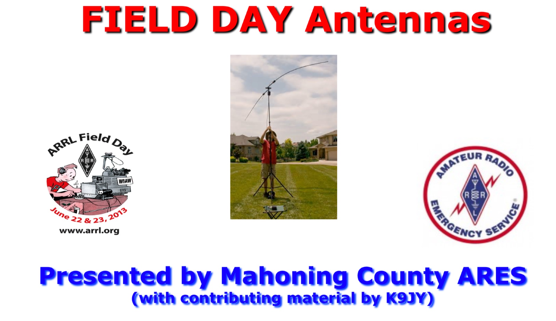 HF VHF UHF antenna ideas to be used for field days. All antennas are quick to set up and take down and offer proven performance and flexibility. Presentation offered by Mahoning Country ARES
 -
 Essentially, a choke balun is designed to 'divorce' your antenna from the feed line. if your feed line is coaxial cable then you don't want it to be part of your antenna. you want to be able to deliver all your power to the radiator itself, i.e. 'the antenna'. a choke balun does this admirably
 -
 The article, "Using 75 Ohm CATV Coaxial Cable," details methods for employing readily available 75-ohm CATV hardline in standard 50-ohm amateur radio setups. It addresses the inherent impedance mismatch and practical considerations, such as connector compatibility, for hams seeking cost-effective, low-loss feedline solutions. The resource specifically contrasts common 50-ohm cables like RG-8, RG213, and _LMR-400_ with 75-ohm hardline, highlighting the latter's lower loss characteristics, particularly at VHF and UHF frequencies. It explores two primary approaches to manage the impedance difference: direct connection with an acceptable SWR compromise and precise impedance transformation. The direct connection method acknowledges that a perfect 1:1 SWR is not always critical, especially when using low-loss coax. For impedance transformation, the article explains the use of half-wavelength sections of coax to reflect the antenna's 50-ohm impedance back to the transmitter, noting its single-frequency effectiveness. It also briefly mentions transformer designs using toroid cores and a technique involving two 1/12 wavelength sections of feedline for broader bandwidth. The content further clarifies the concept of _velocity factor_ for calculating electrical versus physical cable lengths, providing a generic formula for precise length determination. It notes that while half-wave matching is practical for 10 meters and above, it can result in excessively long runs for lower bands like 160 meters, potentially adding **250 feet** of cable. The article also mentions achieving a usable bandwidth of 28.000 MHz up to at least **28.8 MHz** on 10 meters with specific transformation techniques.
 -
 1:49 UNUN using two stacked FT240-43 cores for end fed halfwave antenna. To match the end fed half wave antenna to the coaxial feeder, it is necessary to have a matching network or transmission line transformer.
 -
 This web article details the construction of a 4-meter band coaxial dipole antenna, designed for operation between **70.000 MHz and 70.500 MHz**. The resource provides a bill of materials and step-by-step assembly instructions for a half-wave dipole constructed from _RG-58_ coaxial cable. The design specifies a direct 50 ohm feedpoint impedance, eliminating the need for an external matching network. Construction photographs illustrate the stripping and soldering processes for the coaxial cable elements, ensuring proper electrical connection and physical integrity. The article includes specific dimensions for the radiating elements, derived from calculations for the 70 MHz band. The project outlines the physical dimensions required for resonance at 70 MHz, with the outer braid forming one half and the inner conductor forming the other. The feedline connection is directly to the coaxial dipole's center, maintaining a 50 ohm characteristic impedance. While the article does not present SWR plots or VNA sweeps, it focuses on the mechanical construction and dimensional accuracy for achieving a functional 4-meter dipole. The design is intended for fixed station use, with no specific mention of polarization or height above ground, but implies a standard horizontal orientation for dipole operation. DXZone Focus: Web Article | 4m Coaxial Dipole | Construction Guide | 50 ohm Feed
 -
 Two different ways to create autotransformer for end fed half wave wire antennas, by using ferrite or air core.
 -
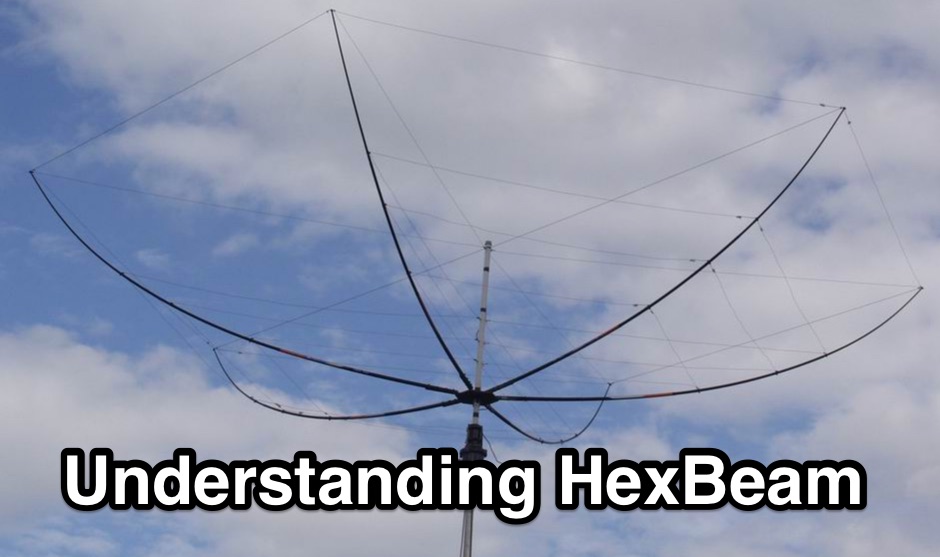 The Hexbeam is a great little antenna! It should be high on your list of options if you want a design that can be multi-banded, exhibits useful gain and directivity, is very lightweight, has a small turning radius, and which lends itself readily to Do It Yourself construction.
 -
 The collinear antenna, or Marconi-Franklin antenna, is an omnidirectional, high-gain antenna composed of in-phase half-wave dipoles aligned vertically. By using quarter-wave transmission line segments, it maximizes gain at a low horizon angle, outperforming a half-wave dipole. Adding segments increases gain but narrows bandwidth. A popular DIY version, the CoCo antenna, uses half-wave coaxial cable segments connected by non-radiating transmission lines. Built with stable velocity factor cables, a matching quarter-wave sleeve balun, and ferrite rings for attenuation, the antenna achieves performance comparable to commercial models.
 -
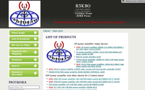 R3KBO is an amateur radio club producing and developing amateur radio kits and assembled products including HF VHF Power Amplifiers or RF Power Kits and amplifier parts, low pass filfers, band pass filters, sourge protections, splitters and combiners, antenna switches
 -
 K1JJ presents a compilation of insights regarding vertical radial ground systems, specifically applied to 160m vertical arrays. The resource details 19 distinct observations and recommendations, emphasizing that ground radials primarily reduce ground losses rather than influencing pattern formation. It explains that RF current flows inefficiently through average soil, necessitating copper radials to create a low-resistance path back to the antenna base. The content suggests that **50-60 radials** are generally sufficient to achieve optimal efficiency, with diminishing returns beyond that number, and that radials should be laid on the surface for best performance. The discussion also addresses practical aspects such as wire gauge, installation techniques using 'U' shaped staples, and methods for connecting radials in multi-element arrays. It highlights the importance of radial length, stating that 1/4 wave radials are a crucial minimum, and that for 160m, radials should be at least _100 feet_ long. The resource critically examines the efficacy of elevated radials versus ground radials, noting that while a few elevated radials may suffice for VHF, HF applications, particularly on 160m, require extensive ground radial systems to efficiently collect RF currents in the near field. It also touches on the impact of radial systems on parasitic elements and the significance of symmetrical radial patterns for minimizing losses. Further practical advice includes wire type recommendations, proper soldering and weatherproofing techniques for radial connections, and considerations for integrating steel towers into the ground system. The author shares personal experience with installing 60 quarter-wave and half-wave radials under each of three in-line verticals, expressing satisfaction with the results.
 -
 How to home made antenna traps with material you can easily find, and how to properly tune it.
 -
 Complete collection of the four main parts of this excellet research on modelling and designing half wave dipole antennas for 40 meters band, covering all aspects beginning from full wave length antennas, to shortened, loaded and reshaped dipoles
 -
 Low Band Receiving Antenna, it is a ground independent Receiving antenna which only needs two 10m support poles by DH1TW
 -
 If you like building good antennas, this one is for you. The J-pole is a slim, omnidirectional, half-wave antenna fed at the end through a quarter-wave shorted transmission line. Its predecessor is the famous Zepp antenna developed for the Zeppelin airship.
 -
 Selecting appropriate coaxial cable and wire for demanding amateur radio applications, particularly those involving high power or harsh environmental conditions, is crucial for maintaining signal integrity and operational safety. This resource details Harbour Industries' specialized offerings, which include Mil-Spec and commercial designs such as NEMA HP3/HP4 and SAE AS22759, suitable for aerospace, military, and industrial sectors. Their product line addresses the need for robust conductors capable of withstanding extreme temperatures and mechanical stress, often encountered in antenna systems or amplifier interconnections. The company highlights its AeroPOWER® Firezone M25038/3 cable, specifically engineered for high-temperature environments like aircraft engines. This particular product exemplifies their focus on solutions for critical infrastructure where reliability under adverse conditions is paramount. Such cables are relevant for hams building or maintaining stations in challenging climates or those operating high-power amplifiers where internal wiring must endure significant thermal loads. Harbour Industries also provides a range of high-performance cables designed to meet stringent specifications. Their expertise in high-temperature and high-performance cable manufacturing positions them as a supplier for specialized wiring needs beyond standard off-the-shelf options, ensuring durability and performance for advanced amateur radio setups.
 -
 Full article on how to build a home-made wire dipole antenna for 40 and 80 meters band. Article is fully in italian, as it was published on ARI RadioRivista, but is plenty of self explaining pictures that will guide you on homebrewing this trapped dipole antenna for the lower amateur radio bands.
 -
 A trapped multi band end-fed-half-wave antenna for 40/30/20/17/15m.
 -
 9M6MU Alfons details his family's efforts to establish an independent, self-sufficient home at Eagle Plateau in Borneo, a 50-acre highland property. The resource highlights their integration of **solar photovoltaic panels** for power generation, alongside managing water supplies, organic gardens, and fruit trees. It covers the practical challenges and rewards of living off-grid, including maintaining power generators and addressing infrastructure needs, all while pursuing the hobby of amateur radio. The narrative emphasizes a holistic approach to healthy living and nature conservation, reflecting the family's aspirations for an ideal ham world. Alfons and his XYL Doris share their experiences in building shelter and antenna farms, showcasing their dedication to independence and sustainable practices away from the conventional grid. The site also references the Hillview Gardens Amateur Radio Club, suggesting community involvement.
 -
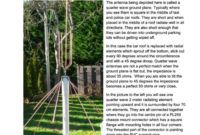 Adapted from a similar project by NA4IT. Made with one quarter wave 2 meter radiating element pointing upward and it is surrounded by four 70 cm elements.
 -
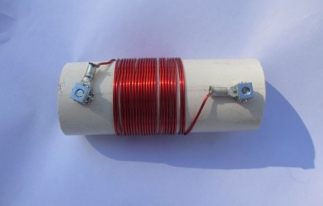
 This antenna is designed for stations having a difficult time putting a decent signal on 160M from small or CC&R d lots. It is a 24.5 ft. vertical antenna, made from three 10 ft. PVC sections bolted together, and half wavelength of antenna wire helically wound around the PVC sections.
 -
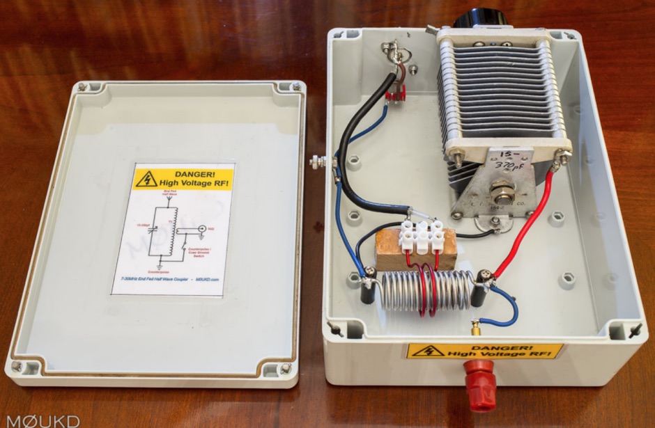
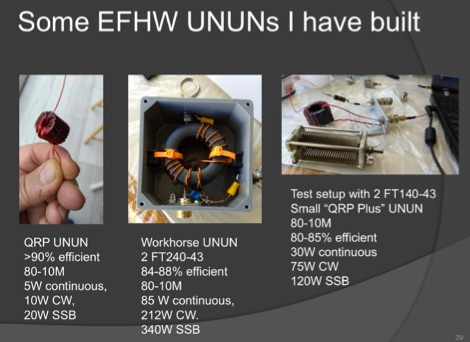 A very well done presentation about End-Fed Half-Wave antennas. This PDF document contains a summary of experiences in how to build custom EFHW antennas. Includes an interesting comparison table of UnUn configurations with recommended toroids, Wire size, turns and capacitors. An useful recap on common errors in building homebrew EFHW Ununs completes the document.
 -
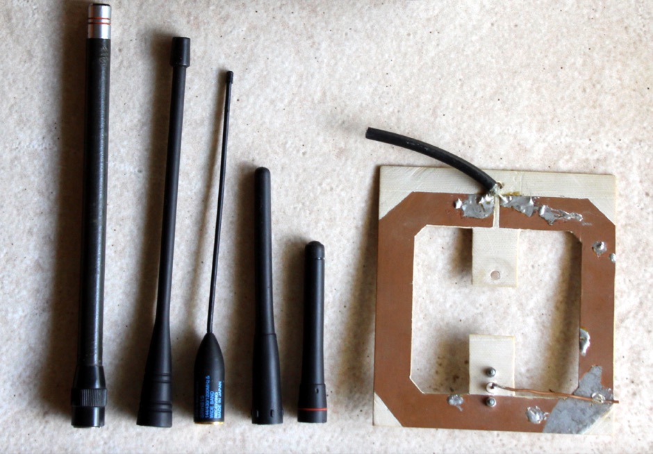 In this article the author analyze six different type of VHF handheld antennas and as result of his self training on his new vector network analyzer published this interesting report
 -
 Comprod Communications specializes in the design and manufacturing of RF communication solutions, including a comprehensive range of antennas, duplexers, multicouplers, and combiners. The resource details their product categories, which encompass base station antennas, mobile antennas, transit antennas, and disguised antennas, alongside mounting solutions and in-building systems. It highlights the company's 40-year history in adapting offerings to client needs and anticipating industry trends, emphasizing product durability and low maintenance for harsh environments. The company's offerings are presented as high-quality, designed to withstand extreme conditions from Arctic cold to equatorial heat and humidity. The site mentions solutions and technical sales support, training, and site analysis and system design as part of their service portfolio. It also references being a market leader trusted by over 1,000 customers worldwide, positioning itself as a partner for RF communication needs.
 -
 Cmpter Electronics specializes in the design and manufacturing of RF coaxial connectors, RF adapters, and RF cable assemblies, serving diverse applications across datacom/telecom, automotive, instrumentation, aerospace, and defense sectors. Their product line includes RF coaxial terminations, attenuators, and waveguide to coax adapters, catering to specific needs in radio frequency systems. The company also offers precision adapters and connectors, alongside glass beads and test cable assemblies, indicating a focus on high-quality components for demanding RF environments. Their resource center provides valuable information, including an "RF Made Simple" section and a product catalog for download, which assists engineers and technicians in selecting appropriate components. The product named system helps in identifying specific parts, streamlining the procurement process for complex RF solutions. With a comprehensive range of RF coaxial cables and related tools, Cmpter Electronics positions itself as a key supplier for critical infrastructure requiring reliable signal integrity. Their offerings support a broad spectrum of RF applications, from basic connectivity to advanced test setups.
 -
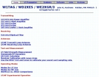 Experimental Stations Run by W1TAG WD2XES has been used to study LF antenna design, propagation and communication modes. Signals from WD2XES have been copied as far away as Russia.
 -
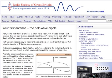 RSGB article for beginners. How to build a dipole antenna, construction tips and correct setup of inverted-ve dipole antennas
 -
 Designing and constructing a two-element receiving loop antenna array for HF operation involves specific considerations for achieving high directivity and noise reduction. This resource details a homebrew system comprising two 30-inch diamond-shaped loops, spaced 20 feet apart, which are fed through mast-mounted preamplifiers and passive signal combiners. The operational principle relies on adjusting phase delays between elements via precise _Belden 8241_ coaxial cable lengths, optimized for specific bands from 160m to 20m. Performance data, derived from _EZ-NEC_ modeling, illustrates consistent 90° azimuth-plane beamwidth and low take-off angles across the target bands, with _Receiving Directivity Factor_ (RDF) values comparable to a 300-foot Beverage antenna. The article presents detailed elevation and azimuth plots for 20m, 30m, 40m, 80m, and 160m, demonstrating the array's ability to provide strong response at low DX angles while also supporting _NVIS_ signals. Key components like the _DX Engineering RPA-1_ preamplifier and _DXE RSC-2_ signal combiner are discussed, alongside the importance of impedance matching to preserve antenna patterns. The construction emphasizes self-contained elements that do not require ground radials, offering a compact solution suitable for suburban environments and stealth installations, with a focus on optimizing receive performance independently from transmit antennas.
 -
 DF0WD DL4YHF Longwave Station include a linear transverter and antenna tuner
 -
 Constructing an End-Fed Half-Wave (EFHW) antenna offers a practical solution for HF operators seeking a multiband wire antenna without the need for extensive radial systems. This design typically employs a high-impedance transformer at the feed point, matching the antenna's inherent high impedance to a 50-ohm coaxial feedline. The article specifically details a 2012 approach, focusing on a transformer with a 49:1 turns ratio, which is a common configuration for EFHW antennas. The resource outlines the construction of a wire element cut for a half-wavelength on the lowest desired band, with specific coil arrangements enabling operation on harmonically related bands such as 40m, 20m, and 10m. It discusses the physical dimensions and winding details for the matching transformer, often utilizing a ferrite toroid core to achieve the necessary impedance transformation. The content provides insights into the operational principles and practical considerations for deploying such an antenna, including methods for tuning and optimizing performance across multiple amateur radio bands. While acknowledging that the presented information from 2012 may be superseded by newer insights, it serves as a foundational reference for understanding EFHW antenna theory and construction.
 -
 The ZS1J/B beacon operates on 28.2025 MHz with 5 Watts output to a half-wave, end-fed vertical antenna, initially installed in 1977 as ZS5VHF near Durban. The 10-meter transmitter is a modified 23-channel CB radio, and the identification keyer uses a diode matrix unit with TTL ICs from the same era. After relocation to Plettenberg Bay in 1993, the beacon has been in continuous service, with additional QRP transmitters later installed for other bands. In 1994, a single-transistor, 80-meter, 0.5-watt QRP transmitter with a half-wave dipole was added on 3586 kHz, followed by a 160-meter, 0.5-watt unit on 1817 kHz. A 30-meter, 0.5-watt transmitter was installed in 1996, operating on 10.124 MHz. In 2002, a 40-meter QRRP beacon on 7029 kHz, with an output of 100 microwatts, achieved DX reports up to 1100 km from ZS6UT in Pretoria. Best DX reports for the 80m and 160m beacons came from 9J2BO.
 -
 Welcome to our line of Low Frequency, Natural Radio Research, Broadcast, Marine and Shortwave products. Our evolving product line is the result of our dedicated research efforts primarily in the areas of LF, VLF, MF, and HF.
 -
 Low-frequency (LF) radio time signals, operating primarily in the 40–80 kHz range, are broadcast by national physics laboratories for precise clock synchronization. Transmitters like **JJY** (40 kHz, 50 kW; 60 kHz, 50 kW), RTZ (50 kHz, 10 kW ERP), MSF (60 kHz, 15 kW ERP), WWVB (60 kHz, 50 kW ERP), RBU (66.66 kHz, 10 kW), and DCF77 (77.5 kHz, 50 kW) cover vast geographic areas, often several hundred to thousands of kilometers. LF signals offer distinct propagation advantages over higher-band transmissions such as GPS. Their long wavelengths (3–6 km) enable effective diffraction around obstacles like mountains and buildings. The ionosphere and ground act as a waveguide, eliminating the need for line-of-sight and allowing a single powerful station to cover extensive regions. Ground wave propagation minimizes ionospheric variability effects on transmission delay, and signals penetrate most building walls effectively. Robust and low-cost receivers, often priced at 20–30 USD/EUR, are widely used in radio clocks. These receivers typically comprise a tuned ferrite core antenna, a receiver IC (e.g., Atmel T4227, U4223B, MAS1016) for amplification and AM detection, and a microcontroller for decoding the time signal and phase-locking a local clock. Specific components for DCF77, MSF, and WWVB are readily available from vendors like HKW Elektronik and Ultralink.
 -
 The Windom antenna, one of the oldest antennas developed for amateur use, has had a complicated history, one as interesting as the theory of the antenna itself.
 -
 Accessing antennas at great height poses many potential safety hazards. Essentially, climbing ladders or scaling towers, regardless of whether or not a commercial safety harness is fitted, is risky business indeed particularly for those hobbyists in their latter years or not as physically capable as others.
 -
 An interesting article on end fed half-wave wire antennas with a couple of original experiments. Author illustrate the role of the QRP matchbox, and a 40/20 meter antenna with a center stub making it a large bandwidth antenna for 40 and 20. Includes also an 80/40 end fed with the typical coil to make it available on 80 merts band.
 -
 A home made end-fed half-wave antenna coupler with antenna lenght calculator and counterpoise calculator based on center frequency. Includes pictures and drawings along to antenna homebrewing instructions with a home made on air wound transformer
 -
 A rotary dipole antenna for 30 meters band. Each arm is about 12.5 ft and is constructed from telescoping fibreglass flag/fishing poles and short lengths of aluminium tubing. Two short lengths of glass-fibre rod were used to insulate the arms from the supporting hardware.
 -
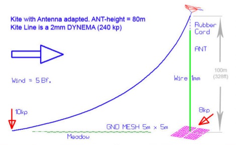 An essential kite antenna plan for the top band, Antenna has been tested at half wave and quarter wave.
 -
 Author experiments end fed half wave antennas using common two conductore speaker wire, this article features a couple of end-fed halfwave wires for the 40M and 20M bands.
 -
 High Speed Multimedia (HSMM) radio, as introduced by John Champa, K8OCL, represents a significant advancement in amateur radio's digital capabilities, moving beyond traditional keyboard modes like packet radio. This initiative, driven by ARRL's Technology Task Force, focuses on developing high-speed digital radio networks capable of up to 20 megabits per second. HSMM primarily facilitates digital voice (DV) and digital video (ADV), enabling real-time video transmission from emergency scenes to an EOC without expensive ATV gear, often requiring only a laptop, a PCMCIA card, a digital camera, and a small antenna. The working group's initial efforts concentrate on cultivating microwave skills within the amateur community to build and support portable and fixed high-speed radio-based local networking, or **RLANs**. These networks prove invaluable for RACES and ARES organizations, as well as homeland security and other emergency communications. Field Day exercises and simulated emergency tests (SETs) are encouraged to hone skills in rapid site surveys and deploying broadband HSMM microwave radio networks, with examples like linking Field Day logging stations or antenna test results at the Midwest VHF-UHF Society Picnic 2003. Getting started with HSMM often involves adapting off-the-shelf **IEEE 802.11** (WiFi) equipment to comply with amateur radio regulations, typically operating in the 2.4 GHz ISM bands. While consumer WiFi gear has range limitations under Part 15 rules, proper setup under amateur regulations can extend coverage significantly, with test networks like the Hinternet achieving 5-15 mile ranges at 54 M bit/s using small mast-mounted dish antennas. Careful selection of equipment with external antenna ports, high transmit power, and low receive sensitivity is crucial, along with using low-loss coaxial cable like LMR-400 for optimal performance at these frequencies.
 -
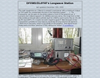
 DF0WD/DL4YHF's Longwave Overview details amateur radio operations on the 135.7 to 137.8 kHz segment in Germany. The author outlines the "inofficial" European band plan, specifying segments for QRSS, TX tests, beacons, conventional CW, and data modes. Early LF activities at DF0WD began with a 20-watt CW transmitter, later upgraded to a homemade linear transverter capable of 100 watts, driven by an Icom IC706 on 10.137 MHz. The station's antenna system includes a 200-meter wire, approximately 10 meters above ground, supported by football field light-masts. Despite its length, the antenna's efficiency is noted as very low due to the immense wavelength of about 2.2 km. The author's experience highlights the significant challenge of achieving effective radiated power (EIRP) on LF, estimating DF0WD's EIRP at around 80 milliwatts based on field strength measurements from PA0SE. DF0WD/DL4YHF has successfully worked numerous countries on 136 kHz CW, including DL, F, G, GI, GM, GU, GW, HB9, HB0, LX, OE, OH, OK, OM, ON, OZ, PA, and SM. The author also mentions ongoing efforts to log contacts with CT, EI, LA/LG, and to complete a two-way QSO with Italy, demonstrating persistent activity on this challenging band.
 -
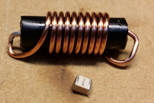
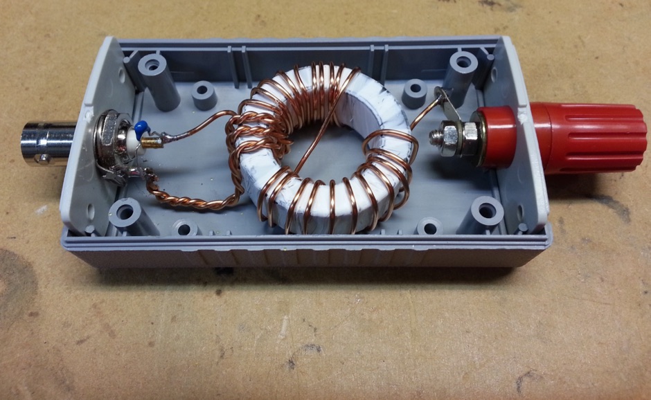 An end-fed half wave antenna matching unit made of 3:24 turns ratio on a FT140-43 toroid with a 150pF capacitor across the input.
 -
 The BikeLoop antenna project details the construction of a double magnetic loop antenna optimized for VLF frequencies, specifically around 136 kHz. This innovative design incorporates two orthogonal loops, which significantly enhance reception capabilities. Key construction hints include utilizing lightweight bicycle rims for the antenna structure, making it easy to transport and set up in various locations. The document provides valuable mathematical and electrical insights into the antenna's performance, alongside practical reception tests conducted in the Italian Alps, showcasing its effectiveness in capturing various VLF signals, including Sferics and FSK transmissions. Proper setup is crucial for optimal performance. The project emphasizes the importance of grounding and avoiding interference from nearby electrical sources. The reception tests revealed the antenna's ability to capture a range of signals, demonstrating its practical application for enthusiasts interested in VLF reception and antenna experimentation. Overall, the BikeLoop serves as an excellent starting point for those looking to explore the world of VLF frequencies and enhance their antenna-building skills.
 -
 This page delves into the Inverted V antenna, a source of myths among ham radio operators. The author explores the behavior of this antenna type with a focus on a 20m half-wave dipole positioned 10m above the ground. From Pythagoras to high school math, the article simplifies the calculation of dimensions and angles for setting up an Inverted V antenna. It includes a spreadsheet for calculating hypotenuse length and angles, crucial for antenna setup. Additionally, it provides insight into the radiation pattern of a 'flat' half-wave dipole at 10m height. Useful for hams planning to optimize their antenna setup. In Norwegian.
 -
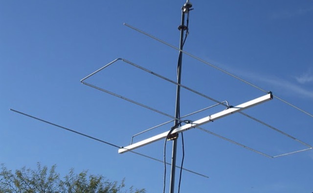 A short 3 element LFA Yagi for 50MHz with a 1.94M boom. This antenna has been designed in order to minimise the upward and downward lobes typically seen the the EL plane on Yagi antennas.