Search results
Query: 50 MHz
Links: 404 | Categories: 8
Categories
- Operating Modes > 50 MHz
- Antennas > 6M > 6 meter Moxon Antennas
- DX Resources > Beacons > 6 meters beacons
- Antennas > 6M
- Radio Equipment > HF Transceivers > Icom IC-703
- Radio Equipment > HF Transceivers > Icom IC-7610
- Radio Equipment > HF Transceivers > Icom IC-7760
- Manufacturers > Antennas > VHF UHF Microwave > Microwave antennas
-
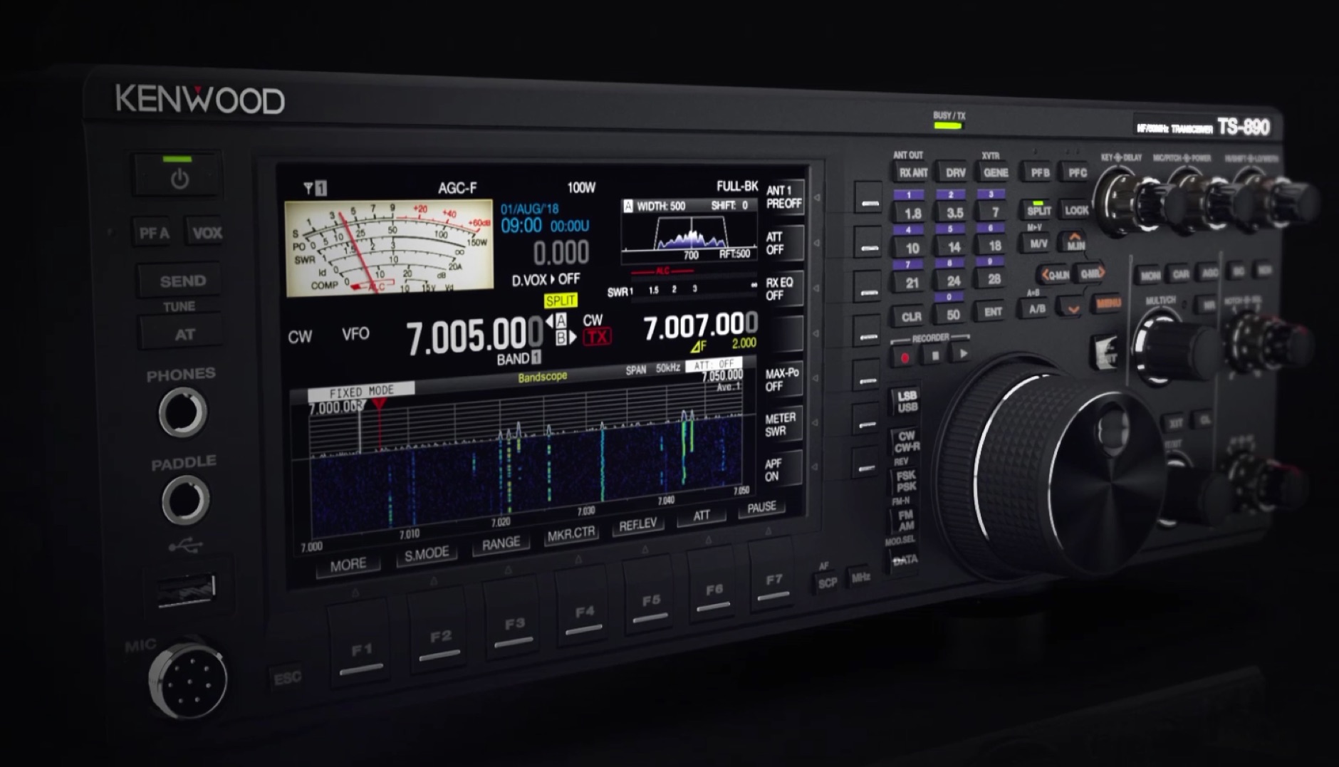 Receiver performance review of the Kenwood TS-890S HF,50MHz,70MHz amateur radio transceiver by Sherwood Engineering
 -
 50MHz DX Bulletin edited by O. Bjorn Matt Madsen
 -
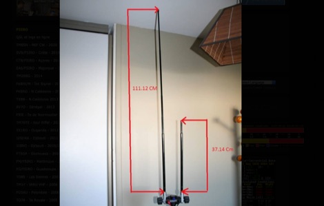
 Documents the construction of a **VHF/UHF** antenna addition for the Buddipole HF antenna system, leveraging the existing Versa-Tee component. The project details the fabrication of a custom antenna mount from angle aluminum, including specific drilling and tapping for 3/16"-24 bolts, and the creation of radials from Simpson Strong Tie Insulation Supports. It specifies radial lengths for 70 centimeters (6 inches from the center stud) and 2 meters (19 1/4 inches), noting the use of wire nuts for safety. The resource outlines the construction of a mast from 1/2" ID PVC conduit, connected with 3/8"-24 connecting nuts and bolts, mirroring the Buddipole's modular design. It describes the integration of a mobile dual-band antenna with a 3/8"-24 mounting stud and the custom coax setup with BNC and **PL-259** connectors. Field testing with an FT-817ND and a separate dual-band SWR meter confirmed good SWR on both 2 meters and the 440-450 MHz section of 70 centimeters, with positive reception reports during Field Day activities. Further, the article describes the creation of a custom carrying solution, including a 22-inch tripod bag and a fabric roll-up, to emulate the portability of the original Buddipole system.
 -
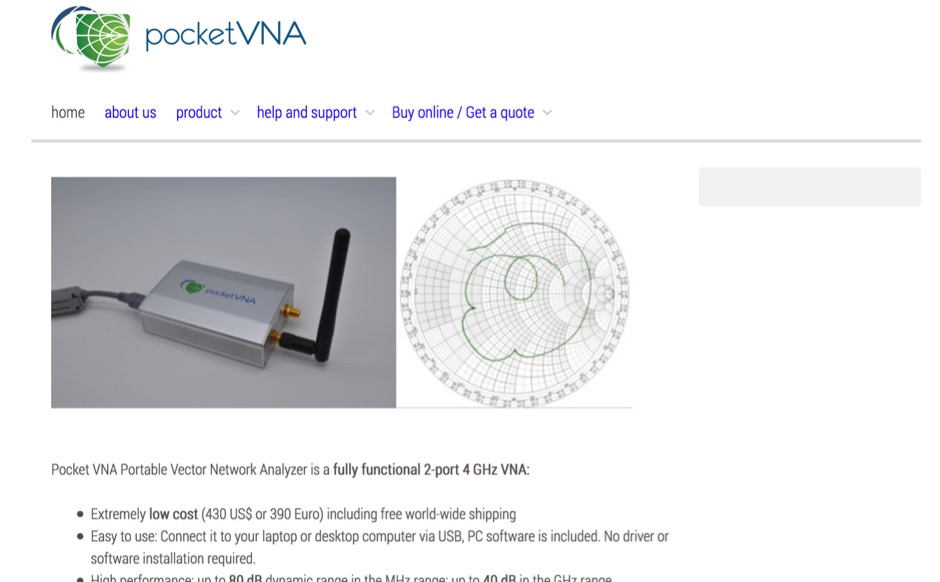 A 500 kHz to 5.5GHz 2-port vector network analyzer designed for use with any Linux, Windows or MacOS computer. High performance: up to 80 dB dynamic range in the MHz range; up to 40 dB in the GHz range
 -
 The Broadcast Employees Amateur Radio Society, Inc. (BEARS) operates an extensive network of **VHF and UHF repeaters** across New York, the Hudson Valley, Long Island, and New Jersey, accessible to all licensed amateur radio operators. This resource details the club's structure as a 501c3 tax-exempt non-profit, emphasizing its role in providing ham radio training, testing, and critical communications support to various public and private emergency response agencies. Key repeaters include W2ABC/RPT on 147.27 MHz with a 141.3 PL tone, serving as a central point for club activities and broader network access. BEARS is also a founding member of the **Disney Amateur Radio Interconnect (DARI)**, a consortium of open, linked VHF and UHF repeaters spanning major metropolitan areas such as Philadelphia, Baltimore/Washington DC, Orlando, Bristol, Los Angeles, and Boston. This interconnected system facilitates wide-area communication for members and supports emergency preparedness efforts across multiple regions. The club's focus extends beyond Disney employees, welcoming aspiring and current hams from outside the company to participate in its activities and utilize its robust repeater infrastructure.
 -
 The Lakeshore Repeater Association (KR9RK) operates a **VHF** 2-meter repeater on 147.270 MHz, utilizing a +600 kHz offset and a 100 Hz PL tone, serving the Raymond, Wisconsin area. The organization provides access to monthly newsletters, with recent editions including March 2026, February 2026, and January 2026, detailing club activities and operational updates. A Google Docs link is provided for newsletters with functional embedded links, addressing issues with PDF versions. The association's Megacycle Group is actively constructing a **DX Contest** level HF network, designed for remote accessibility. This initiative aims to provide members with a competitive edge in global DX hunts by enabling worldwide access to the station's radios. Additionally, the Lakeshore Radio Association is commemorating its 50th anniversary with a special event station, K5O, inviting all members to participate in on-air operations.
 -
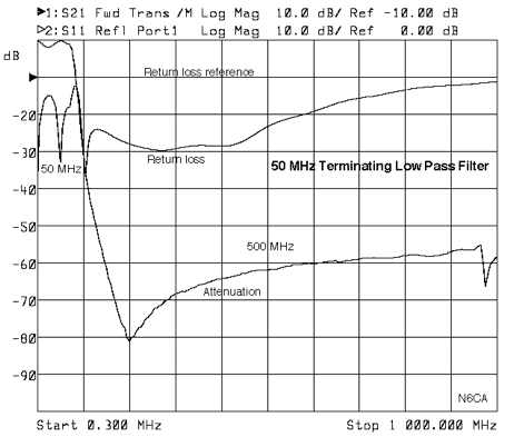 This low pass filter terminates all harmonics from the 2nd to above the 10th harmonic in a better than 15 db return loss load
 -
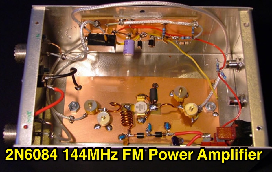 A 144MHz FM class C RF Power Amplifier based on a 2N6084 RF transistor, that can produce 50w output max
 -
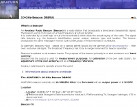 beacon transmits on 10.368,850 MHz in the 3cm-band
 -
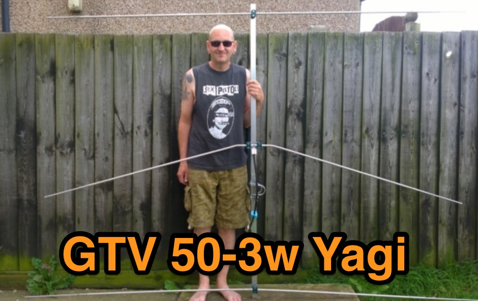
 Plans for building your own 3-element beam for use on 6m.
 -
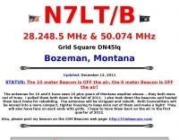 Operating 28.249 MHz and 50.074 MHz from Bozeman, Montana
 -

-
 Six meter band DJ9BV yagi antennas by YT1VP
 -
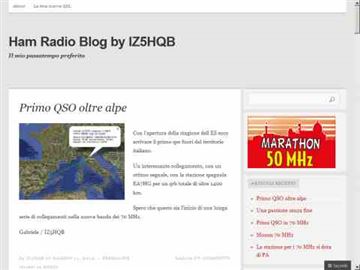 ContestLogHQB is a free windows contest logging program developed by Gabriele IZ5HQB. Currently in Italian, support most of the VHF and Up contests including Maraton 50Mhz.
 -
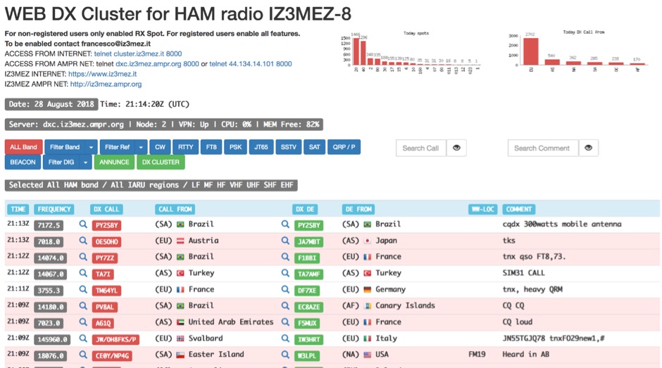 The IZ3MEZ Web DX Cluster presents real-time amateur radio DX spots across 20 distinct frequency bands, spanning from **LF (2190m)** at 135.7 kHz up to **SHF (QO-100)** at 10499 MHz. It displays the DX callsign, frequency, DXCC entity, spotter callsign, and spotter DXCC entity, along with any accompanying comments. The cluster also lists various operating modes such as CW, RTTY, FT8, FT4, FT2, PSK, and SSTV, and supports special operating activities like QRP/P and specific award programs including IOTA, POTA, SOTA, WCA, and JOTA. The cluster's interface provides a dynamic feed of the latest 50 spots, continuously updated with precise timestamps. It offers direct **Telnet protocol** access for users preferring a command-line interface, with configuration instructions provided. The resource also integrates with other spotting networks like RBN and PSK Reporter, enhancing its utility for DXers and contesters seeking propagation information and activity monitoring across a broad spectrum of amateur radio frequencies.
 -
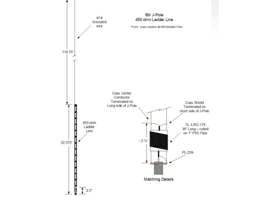 A J-pole antenna plan for 50 MHz based on the DK7ZB design
 -
 IZ5CML, Enrico Giannerini, obtained his amateur radio license in 1998, achieving DXCC contacts with all entities over 18 years of activity. His station, located in Empoli, Tuscany, Italy, focuses on HF and 50 MHz operations, primarily using SSB, CW, and some RTTY. He emphasizes direct radio communication, preferring "human modes" over digital modes like FT8/4, which he views as detaching the operator from the signal. Enrico's operating interests include DXing, IOTA activations, and major HF contests, where he has participated both individually and with teams like IQ5LV and IO5O. Notable activations include Sao Miguel and Flores (CU8, EU-089) in the Azores in 2005, and Antiparos and Paros (EU-067) in Greece in 2006 and 2014. He also contributes to the Hamradioweb forum, promoting good operating practices and publishing the monthly "Dxschedule" for upcoming DX and contest activities. The website includes a blog with articles on DX, ionospheric propagation, and antennas, reflecting his long-standing passion for radio, sparked by the 1980s film "La Tenda Rossa" and years as an SWL.
 -
-
 Much information about 50 Mhz and 2 meters : log , info , links .Also J28VS log.
 -
 Article about a high-gain, narrow-band version feature 7.15 dBd and a F/B 13dB with details on how to setup in array mode
 -
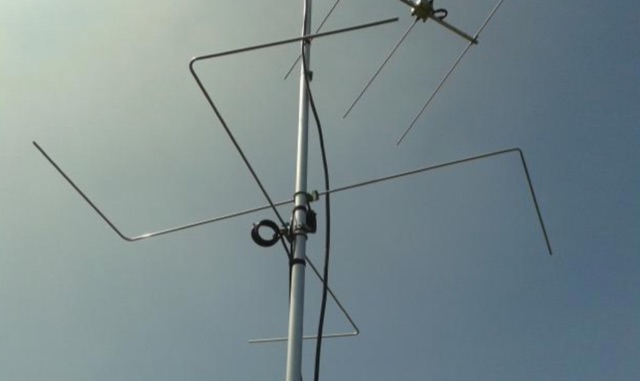 Horizontal polarized omni directional 50MHz Antenna. This antenna is intented to use in a contest station as a second system beside the stacked yagi beam system. An omnidirectional systeem can be an advantage when it comes to short openings on wich the operator must react quickly.
 -
 4 Stacked 4 element yagi for six meters band
 -

-
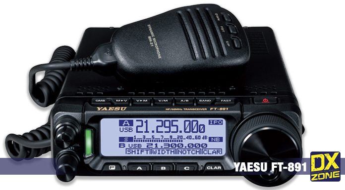 HF/50 MHz 100W All Mode Transceiver. The FT-891 provides stable 100 W (25 W AM) high power output
 -
-
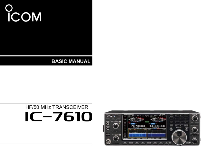 The ICOM IC-7610 SDR HF/50MHz Transceiver Basic Manual in English PDF File 13 MB
 -
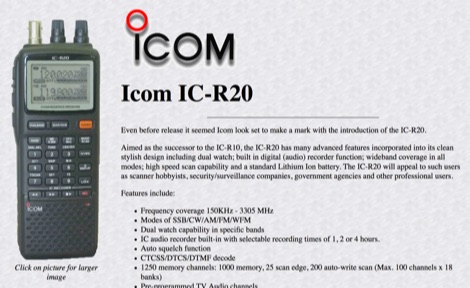 Javiation page dedicated to the ICOM IC-R20 150KHz - 3305 MHz communication receiver
 -
 Constructing a high-performance RF spectrum analyzer up to 1000 MHz requires careful attention to component selection, shielding, and circuit isolation. This resource details a project that improves upon the _Spectrum Analyzer for the Radio Amateur_ design by Wes Hayward (W7ZOI) and Terry White (K7TAU), incorporating ideas from Scotty Sprowls' project, particularly his 1013.3 MHz IF bandpass cavity filter. The analyzer utilizes a Mini-Circuits SRA-11 mixer with a sweeping local oscillator from 1013 to 2013 MHz, feeding into a 4-pole copper pipe cavity filter. The design employs a second SRA-11 mixer with a fixed 1024 MHz LO to produce a 10.7 MHz final IF. This signal then passes through narrowband resolution filters and is processed by Analog Devices AD603 and AD8307 ICs for IF amplification and logarithmic detection, driving an oscilloscope in X/Y mode. The project emphasizes modular construction, using salvaged components and double-sided FR4 material for PCBs, with critical notes on minimizing spurious images through effective shielding and proper voltage regulation for each module. Key components include a Z-Communications V585ME48 VCO for the first LO and a Z-Comm V583ME01 VCO controlled by a Motorola MC145151 PLL for the second LO. An optional Hittite HMC307 step attenuator and K&L 5L121-1000/T5000-O/O low-pass filter manage RF input. Tuning procedures for the 10.7 MHz IF resolution filter are also detailed, showing before-and-after spectrum views.
 -
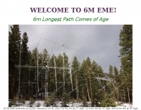 Making EME contacts on six meter band. An US Experience using a pair of 8 yagi arrays for the 50 Mhz.
 -
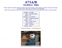 50,006.0 MHz from LL55SH by Qatar Amateur Radio Society
 -
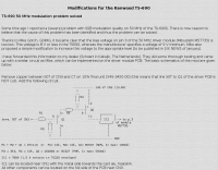 TS-690 50 MHz modulation problem solved
 -
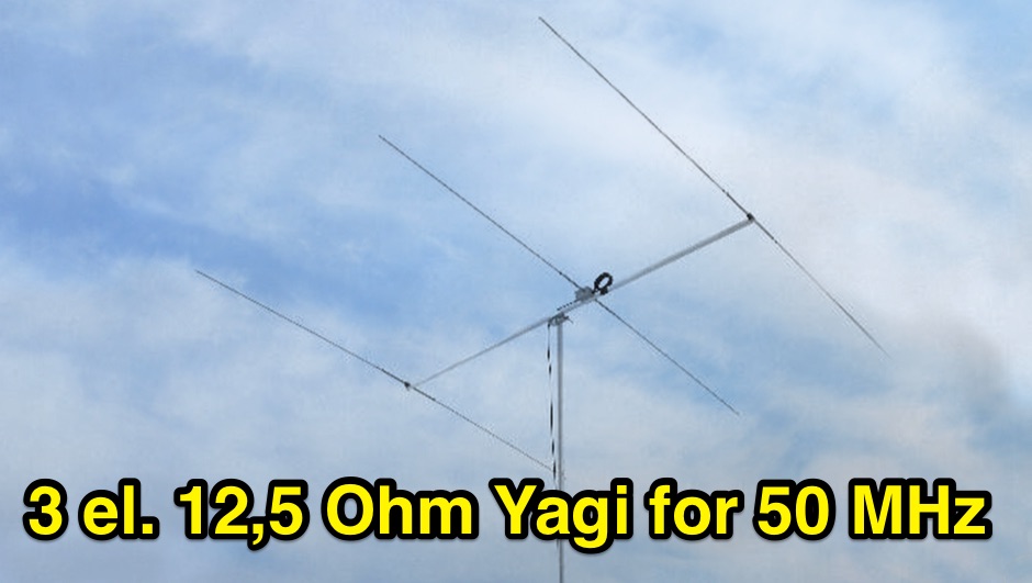
 6 Elements on 50 MHz / 6 metres
 -
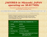 JA6YBR/b in Miyazaki, JAPAN operating on 50.017MHz
 -
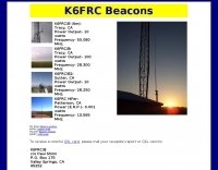 50Mhz 28Mhz 13.5Mhz amateur radio propagation beacons by K6FRC
 -
 Demonstrates the construction of a high-power 6-meter (50 MHz) amplifier, specifically designed for demanding modes like EME, TEP, and multiskip Es. It details the use of a _GU-43B_ tetrode in a grounded-cathode configuration, emphasizing the need for stabilized grid voltage and input capacitance compensation. The resource provides a comprehensive schematic, power supply design, and practical considerations for component sourcing, particularly for high-voltage and high-current sections. The builder achieved an output power of **1250 watts** with an anode current of 0.65 amperes and 3200 volts anode voltage. The article also covers the physical construction within a modified P6-31 enclosure, outlining the internal layout for RF and power supply sections, and includes photos of the completed unit. It highlights critical safety precautions for working with high voltages and reactive currents up to **20 Amperes** in the P-network.
 -
 A compact high G/T Yagi with bent Drive element by DG7YBN
 -
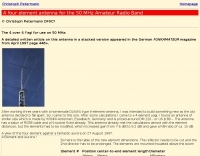
 The antenna described in this article is for 50 MHz, but the design can be scaled for any band, including VHF, UHF, or even the higher HF bands. The antenna is nothing more than a square loop of wire, approximately 30" (or ~76cm) per side. The loop is fed in the middle of one side, and the opposite side to the feed point has a gap in it.
 -
 Icom IC-703 HF + 50 MHz transceiver, english official instruction manual available in PDF File to download.
 -
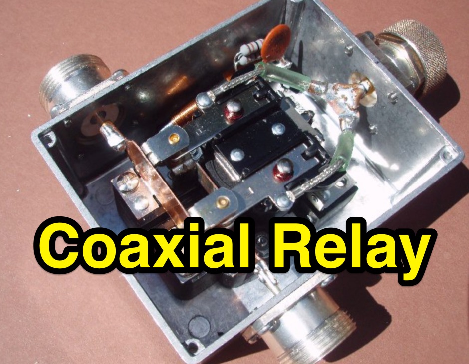 Build a SPDT coaxial relay that can be used as a main Transmit/Receive relay or an A-B switch to select between two different 6m antennas
 -
 A six meter band Marathon managed by ARI Firenze, a 4 month marathon for itailan radio amateurs.
 -
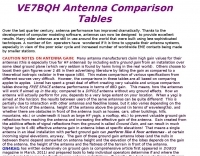
 Article on 50 Mhz Yagi Antennas stacking by OH1ZAA/NN0Y
 -
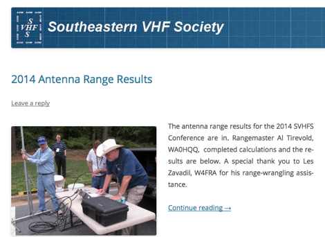 The Southeastern VHF Society (SVHFS) is a not-for-profit organization incorporated to promote amateur radio operation on the bands above 50 MHz in the southeastern United States.
 -
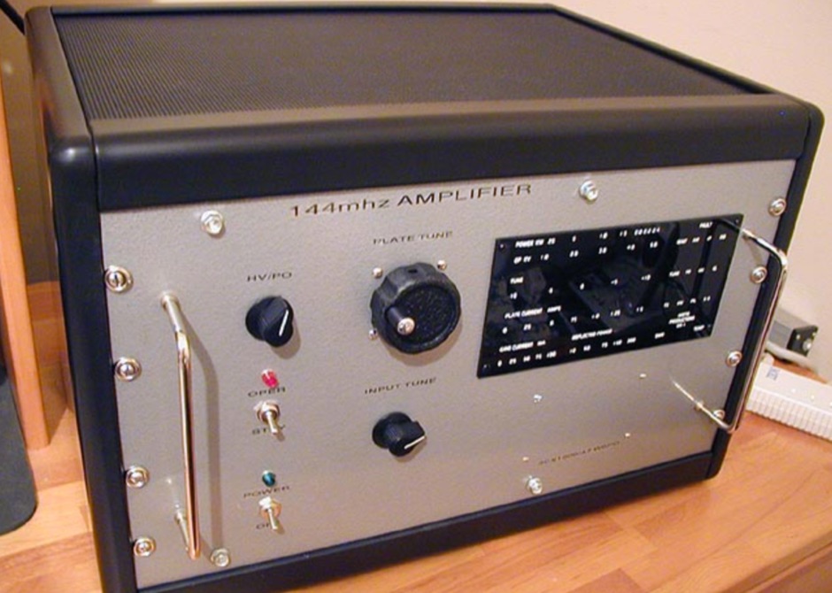 A 3CX1500/A7 8877 144mhz W6PO amplifier, that running a little over 4kv on the plate, this Amp will do over 2kw out.
 -
 Developing operational amateur radio equipment for the 134 GHz band presents significant technical challenges, particularly in frequency generation and stability. This resource details the construction of a 134 GHz system, outlining its architecture with separate transmit (Tx) and receive (Rx) modules, each employing a local oscillator (LO) and RF head units. The system utilizes a dual Flann 50 GHz lens-type horn antenna configuration for optimal signal coupling. The transmit path incorporates an LMX2541 synthesizer chip operating at approximately 2.8 GHz, referenced by a 10 MHz double-oven Morion OCXO for exceptional stability. This signal is multiplied through a series of stages (X4, then X2) to generate a 22.4 GHz signal, which subsequently drives a dual series diode multiplier to produce the final X6 signal for 134 GHz operation. The receive side features an anti-parallel diode mixer coupled to a 144 MHz transceiver via a preamplifier, ensuring effective downconversion. Operational mode is CW, achieved by keying a multiplier stage. The project includes images of the Tx and Rx head units and describes a successful 3.5 km test with G8ACE, demonstrating stable signal tones due to PLLs locked to OCXOs at both ends, confirming the system's robust performance.
 -
 How to setup and configure the buddipole antenna in the J-Pole mode for the six meter band
 -
 Transmitting operations in the 50-54 MHz range offer some unique problems that over the past 50 years have stymied station owners, forcing them to tolerate quiet hours and hostility from family and neighbors attempting to enjoy other electronic services.
 -
 A fand dipole antenna home made for the 7,14,50 MHz. This article descbribes how to homebrew the antenna, hot to setup and some SWR measurements.
 -
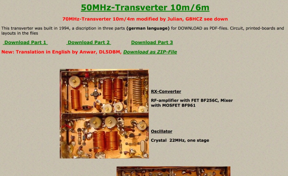 This transverter was built in 1994 and include in this page a pdf with circuit board, and a version of this project for 70MHz.
 -
 A multi-band off centre fed dipole, designed to operate on all bands from 40m (7MHz) to 6m (50MHz). Author claims it will operate on 40, 30, 20, 17, 15, 12 and 10m without an ATU (SWR <3:1) plus 6m with an ATU.
 -
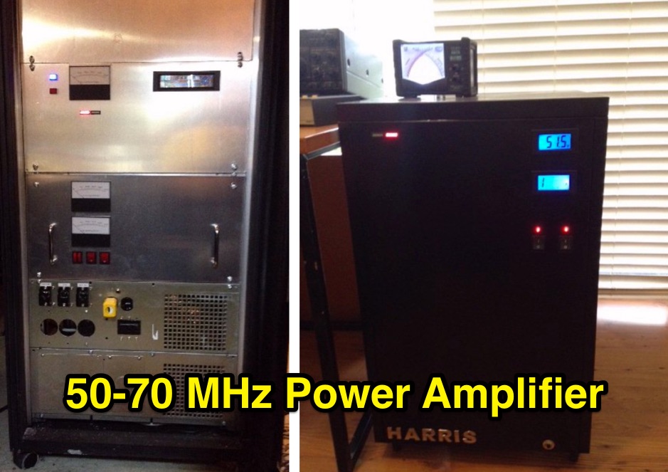 Harris Platinum I Solid State Channel 2, and 3 TV Amplifier Modules for use, on 50 or 70 MHz