Search results
Query: feed
Links: 466 | Categories: 11
Categories
- Antennas > Feed Lines
- Antennas > Resonant Feedline Dipole
- Antennas > Baluns
- Shortwave Radio > Broadcasters
- Antennas > Microwave
- Antennas > Feed Lines > Open Wire
- Internet and Radio > Police Scanners
- Radio Scanning > Police Scanning
- Radio Scanning > RailRoad
- Internet and Radio > Tutorials
- Internet and Radio > Web Cams
-
 Long Beach Los Angeles county live scanner feed
 -
 Based on a simple project based on a 2 elements Yagi for 20m band, and then becomed a triband yagi with a open-sleeve feed system
 -
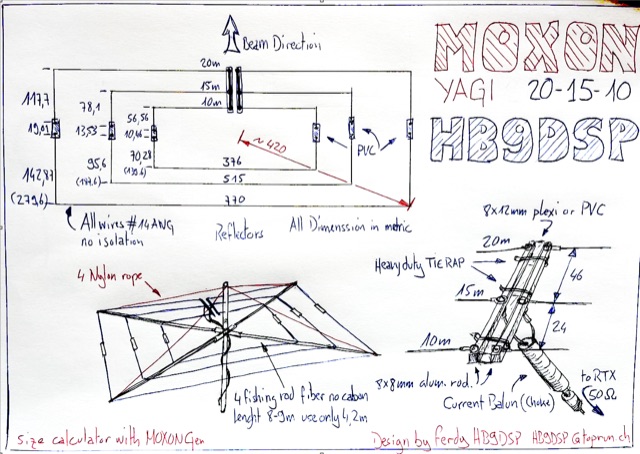 Multi band Moxon Yagi Antenna for 10,15,20 meters band with just one feed line. Drawing and project with dimensions
 -
 The official web-site of the firm IK-Telecom, Finland, manufacturer of base station antenna-feeder systems
 -
 Live feed for NHP rural areas of Moapa Laughlin Primm Alamo Indian Springs
 -
 Presents the construction of a 2-meter **Skeleton Slot Yagi** stack, detailing the design process and practical considerations for VHF operation. The author shares insights from building and testing this antenna, emphasizing its performance characteristics for local and extended range contacts. The project outlines the specific dimensions and materials used, providing a clear path for other radio amateurs to replicate or adapt the design for their own stations. The resource covers the unique aspects of the Skeleton Slot radiator, explaining how its geometry contributes to gain and pattern control. It includes discussions on impedance matching and feedline considerations crucial for optimizing power transfer and minimizing SWR. The article draws on real-world testing, offering practical results that validate the theoretical design. This project serves as a valuable reference for those interested in custom VHF antenna solutions.
 -
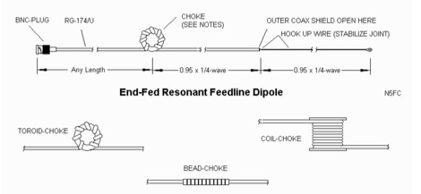
 Building a Resonant Feed line Dipole for 2 Meters
 -
 St. Louis Repeater runs four repeaters in the St. Louis Metro Area, including two with autopatch capability.
 -
 The NB6Zep Antenna, an electrically shortened 80-meter end-fed wire, addresses space constraints for low-band operation by integrating two loading coils into a 37-foot wire. This design, modeled with _EZNEC_, explores configurations like the quarter-wave sloper and inverted-L, with the latter providing a more vertical radiation pattern and practical backyard deployment. The resource details specific coil construction, recommending 21 uH coils made from _BW coil stock #3026_ or similar, and outlines wire segment lengths for optimal tuning. Performance analysis indicates a radiating efficiency of approximately 27% with good ground conductivity, resulting in a signal typically 3-4 dB down compared to a full-size quarter-wave vertical. The antenna exhibits a narrow bandwidth, around 50 kHz, due to its high Q, necessitating a tuner for broader band operation. Feedpoint impedance is low, with ground resistance playing a critical role in achieving a usable SWR. The article emphasizes the importance of an effective ground rod at the feedpoint for proper operation and tuning, suggesting an antenna analyzer for precise adjustments. It confirms the antenna's suitability for DX, citing successful contacts from Oregon to the East Coast and Hawaii on a 160-meter variant, making it a viable option for urban operators seeking low-angle radiation on 80 meters.
 -
 City of Milwaukee Fire Department Live Audio Feed
 -
 A wire antenna feeded with an unsymmetrical feed and a 1:4 balun can be tuned from 6 to 80 meters band but can be noisier than a dipole and cause RF in the shack
 -
 Live Police and Fire scanner feeds from Albion PA, Erie County PA USA.
 -
 Several HD video overlay devices are offered, including the GeoStamp HD, which overlays GPS latitude, longitude, heading, speed, altitude, date, time, and depth onto AHD, HD-TVI, and HD-CVI (720p/1080p) video sources. The VideoStamp HD allows user-defined text overlays on similar HD video inputs, while the VideoStamp Keyboard HD enables text input via a PS/2 keyboard for video overlay. For commercial applications, the PostMark HD integrates with cash registers and POS terminals to overlay transaction data onto security camera feeds. Beyond HD video solutions, the DTMF-8 DTMF Decoder provides remote control capabilities for up to eight devices or relays using touch tones from a radio or other audio source. This decoder supports four operational modes and includes password protection, storing all settings in non-volatile EEPROM memory. The product line also includes standard definition OSD, RS-232, GPS, and POS text inserters, along with various DTMF encoders and DVR solutions.
 -
 Live audio of the National Hurricane Center’s Skywarn Nets. This live feed covers several different states, and locations throughout the US including: TX, LA, MS, AL, FL, GA, SC, NC, VA, MD, DE, PA, NJ, NY, CT, RI, MA, VT, and ME
 -
 Antenna modeling discussions about What happens if... a dipole is bent horizontally, laterally, vertically. Zig-zag, meander, catenary curve. Effect of sag, elevation, radials. OCF off-center feed, harmonics. Includes 4NEC2 antenna models for each study.
 -
 Demonstrating the construction of a short dipole antenna tailored for the 60 meter band, this resource provides detailed instructions for radio enthusiasts with limited space. The design incorporates inductive loading using two inductors (L1/L2) made from PVC tubes, allowing for effective operation on 5 MHz. The antenna consists of 12 meters of wire, divided into four sections, with specific dimensions and materials outlined for optimal performance. Results from users indicate that this antenna can significantly enhance DXing capabilities on the 60 meter band. Feedback from operators suggests that while the design is effective, adjustments may be necessary based on individual setups, such as coil diameter and wire gauge. Many users report successful construction and operation, with some experimenting with variations to improve resonance. The practical application of this antenna design has led to successful contacts and improved signal quality, making it a popular choice among 60 meter band operators.
 -
-
 Illinois Cook County, police scanner includes Chicago Fire Dispatch channels (North, South, and HazMat)
 -
 Balanced feed with coaxial line by John F. Clemens W9ERN
 -
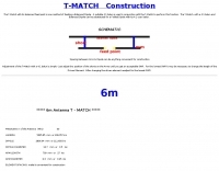 The T-Match with its balanced feed point is one method of feeding a Balanced Dipole.
 -
 Demonstrates the construction and tuning of a **20-17-15 meter fan dipole** using 12-gauge PVC insulated copper wire and an Alpha-Delta C kit feedpoint. The project details the use of 14-inch pine dowels with 6-inch spaced holes to maintain wire separation for the parallel elements. Initial tuning was performed at shoulder height, with final adjustments made after elevation to 38 feet, accounting for frequency shifts observed between ground-level and elevated antenna positions. SWR analysis graphs are presented, showing performance below 1:3 across the entire 20-meter band, below 1:2 for 17 meters, and below 1:3 for 15 meters. The author notes significant RX improvements of +3 to +9 dB, occasionally exceeding +20 dB, compared to a commercial Alpha Delta DX LB Plus. The total hardware cost for this DIY antenna project was approximately $90, with the author emphasizing the utility of an **antenna analyzer** like the RigExpert AA54 for precise tuning. The fan dipole also exhibits tunable resonance on 12, 10, and 6 meters, though with reduced efficiency. Performance comparisons on 20 meters showed the fan dipole outperforming the Alpha-Delta on long-path north-south DX contacts.
 -
 Oakcallsigns.com specializes in custom-crafted oak call signs, presenting various designs for amateur radio shacks. The resource showcases different styles, including standard call sign plaques and options featuring iconic ham radio silhouettes like the _D-104_ microphone. Each item is described with pricing, ranging from $15.00 to **$25.00**, and includes details on shipping and seller reputation. The platform highlights the craftsmanship involved, emphasizing personalized scroll-saw work on each oak piece. It details the seller's positive feedback rating of **99.4%** from over 10,000 transactions, indicating a reliable source for these unique accessories. The site also provides information on the number of units sold for specific designs, such as 2,338 for the standard call sign gift and 554 for the smaller personalized version. This commercial offering focuses on decorative and personalized items for the ham radio enthusiast, distinct from operational equipment. It serves as a direct retail channel for custom shack adornments.
 -
 Experiences with the end-fed dipole based on the concepts presented by J. Taylor in an article titled RFD-1 and RFD-2: Resonant Feed-Line Dipoles in QST. August 1991.
 -
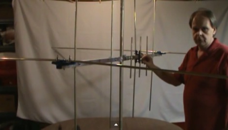 6m/2m/70cm Yagi Antenna Built from Old TV Antenna This turned out to be a great little antenna. It works the 6 meter, 2 meter and 70 centimeter bands. You can use one common feedpoint or two seperate feedpoints depending on how you would like to connect this antenna to your transceiver.
 -
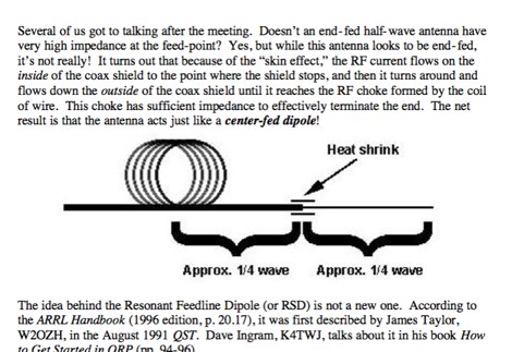 An article on RFD antennas, resonant feed-line antennas
 -
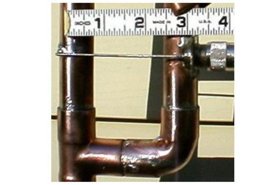
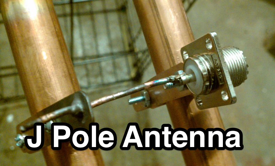 The copper J-Pole antenna soldered in a couple of hours with an interesting method to setup the feeding point
 -
 Wondering whether to spend a fine day with the YL or with the antenna? This article may help you decide by W1GV
 -
 Choosing the right feed line for your antennas, is a critical decision to your station setup.
 -
 Demonstrates the swift setup process for a **Trans World Antenna**, showcasing its utility for portable amateur radio operations. The video highlights the antenna's design for quick deployment, a critical factor for activations like Summits On The Air (SOTA) or Parks On The Air (POTA), where efficiency in establishing a station is paramount. It illustrates the physical components and the sequence of assembly, emphasizing ease of use in varied field environments. The antenna system is presented as a multi-band solution, capable of operating across various HF frequencies. This adaptability makes it a versatile choice for hams engaging in outdoor activities or emergency communications. The visual demonstration provides practical insights into managing the antenna elements and feedline for optimal performance during temporary deployments. The focus remains on the practical aspects of field setup, rather than detailed technical specifications or performance metrics.
 -
 About windom antennas and OCF dipoles, tricks on covering more bands moving feed-points and potential problems. Problems caused by common mode currents in OCF dipoles
 -
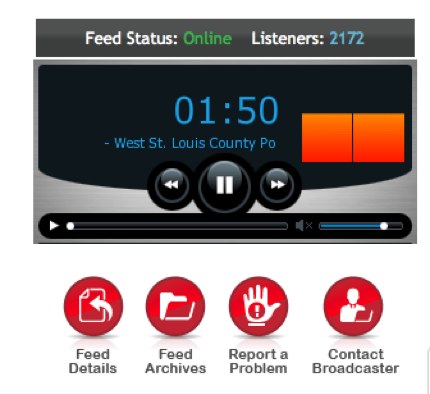 West St. Louis County Police and Fire Live Audio Feed
 -
 A Resonant FeeD line (RFD) antenna for 7 MHz prohect tested and tuned.
 -
 The _Sci.Electronics FAQ: Repair: RFI/EMI Info_ document, authored by Daniel 9V1ZV, provides a detailed analysis of computer-generated RFI/EMI, focusing on its impact on radio reception. It identifies common RFI sources such as CPU clock rates (e.g., 4.77 MHz to 80 MHz), video card oscillators (e.g., 14.316 MHz), and even keyboard microprocessors, all of which generate square-wave harmonics across HF and L-VHF regions. The resource outlines a systematic procedure for pinpointing RFI origins, including disconnecting peripherals and using a portable AM/SW receiver with a ferrite rod antenna to localize strong interference sources. The document categorizes RFI mitigation into shielding, filtering, and design problems, offering practical solutions for each. It recommends applying conductive sprays like _EMI-LAC_ or _EMV-LACK_ to plastic casings of radios, monitors, and CPUs to create effective Faraday cages, emphasizing proper grounding and avoiding short circuits. For filtering, the guide suggests using line filters, ferrite beads, and toroids on power and data lines, and small value capacitors (e.g., 0.01 uF for serial/parallel, 100 pF for video) to shunt RFI to ground. It also discusses the use of bandpass, high-pass, low-pass, and notch filters on the receiver front-end or antenna feed to combat specific in-band noise.
 -
 An overview of coax cable often called coaxial feeder or RF cable, used to feed antennas and deliver radio frequency power from one point to another
 -
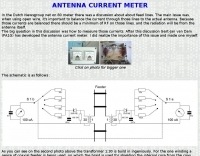
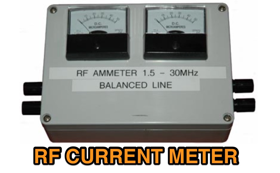 This R.F. current meter was developed to assist in measuring line currents in balance feed lines as used in the All Band HF Antenna.
 -
 Operating a ham station often involves encountering radio frequency interference (RFI), RF feedback, or RF burns, which are frequently misattributed to poor equipment grounding. This resource meticulously dissects these assumptions, asserting that RF grounds on the operating desk often merely mask more significant system flaws. It identifies five primary causes for RF problems, including antenna system design flaws, proximity of the antenna to the operating position, DC power supply ground loops, equipment design defects, and poorly installed connectors or defective cables. The content emphasizes that issues like "hot cabinets" or changes in SWR when connecting a ground indicate substantial RF flowing over wiring or cabinets, a phenomenon known as common-mode current. The article provides detailed explanations of common-mode current generation, particularly from single-wire fed antennas like longwires, random wires, and OCF dipoles, which inherently present high levels of RF in the shack. It also illustrates how vertical antennas, lacking a perfect ground system, can excite feed lines with significant common-mode current. Through simulations, the author demonstrates how a dipole without a proper _balun_ can cause RF problems at the operating desk, showing current patterns and voltage distributions on feed line shields. The discussion extends to the proper application of _RF isolators_ and _ferrite beads_, clarifying their role in modifying common-mode impedance on cable shields and cautioning against their use as a band-aid for fundamental system defects. The resource advocates for correcting the actual source of RF problems, such as antenna system issues or poor connector mounting, rather than relying on internal shack grounding or isolators. It highlights that properly functioning two-conductor feed lines, like coaxial or open-wire lines, should result in minimal RF levels at the operating position, even without a desk RF ground. The author shares personal experience, noting that his stations since the late 1970s have operated without RF grounds at the desks, relying instead on proper antenna system design and feed line integrity.
 -
 Baltimore County Scanner Radio - Live feed
 -
 Current program schedules, RealAudio feeds, and listening tips from Belgian Public Radio which broadcasts worldwide in Dutch, German, French and English.
 -
 Constructing a compact directional antenna for the 17-meter band, this resource details the build process for a Moxon rectangle, a two-element Yagi variant with folded-back elements. It covers the antenna's evolution from the _VK2ABQ beam_ and provides specific dimensions for a version built using fishing pole whips. The content includes a discussion of the antenna's radiation pattern, feedpoint impedance, and its inherent front-to-back ratio, which is often superior to a standard two-element Yagi. Practical considerations for element spacing and material choices are also addressed, alongside a visual representation of the antenna's physical layout. Performance data presented includes a comparison showing the Moxon rectangle's **2.5 dB gain** over a half-wave dipole and a front-to-back ratio of **20 dB**. The resource also touches upon the antenna's relatively wide bandwidth for a two-element beam and its suitability for portable operations due to its compact footprint. It offers insights into optimizing the design for specific operating conditions and discusses the advantages of its lower take-off angle compared to omnidirectional wire antennas, making it effective for DX contacts on the 17-meter band.
 -
 Amateur radio repeater scanner at Pomona California
 -
 A copper J Antenna for 144 and 430 article with design, feeding methods and pictures
 -
 T2FD is a 600-900 ohms folded dipole, terminated with resistor. Feed impedance is coupled with 50/600 ohms voltage balun. It is a wide band antenna with rather low SWR over the full designed frequency range: antenna tuner is seldom needed.
 -
 Council Bluffs area Sheriff, Police, Fire, and State Police IOWA
 -
 This tutorial will get you on the road to running your own live scanner feed on the Internet, be it railroad, fire/ems or law enforcement related.
 -
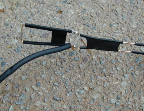
 Essentially, a choke balun is designed to 'divorce' your antenna from the feed line. if your feed line is coaxial cable then you don't want it to be part of your antenna. you want to be able to deliver all your power to the radiator itself, i.e. 'the antenna'. a choke balun does this admirably
 -
 The article, "Using 75 Ohm CATV Coaxial Cable," details methods for employing readily available 75-ohm CATV hardline in standard 50-ohm amateur radio setups. It addresses the inherent impedance mismatch and practical considerations, such as connector compatibility, for hams seeking cost-effective, low-loss feedline solutions. The resource specifically contrasts common 50-ohm cables like RG-8, RG213, and _LMR-400_ with 75-ohm hardline, highlighting the latter's lower loss characteristics, particularly at VHF and UHF frequencies. It explores two primary approaches to manage the impedance difference: direct connection with an acceptable SWR compromise and precise impedance transformation. The direct connection method acknowledges that a perfect 1:1 SWR is not always critical, especially when using low-loss coax. For impedance transformation, the article explains the use of half-wavelength sections of coax to reflect the antenna's 50-ohm impedance back to the transmitter, noting its single-frequency effectiveness. It also briefly mentions transformer designs using toroid cores and a technique involving two 1/12 wavelength sections of feedline for broader bandwidth. The content further clarifies the concept of _velocity factor_ for calculating electrical versus physical cable lengths, providing a generic formula for precise length determination. It notes that while half-wave matching is practical for 10 meters and above, it can result in excessively long runs for lower bands like 160 meters, potentially adding **250 feet** of cable. The article also mentions achieving a usable bandwidth of 28.000 MHz up to at least **28.8 MHz** on 10 meters with specific transformation techniques.
 -
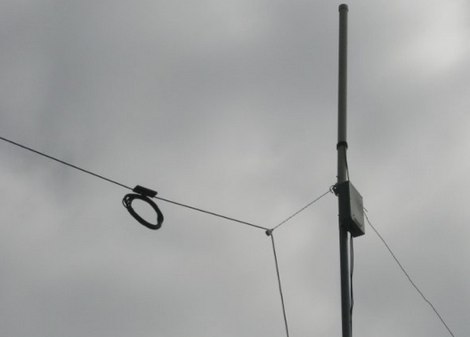
 1:49 UNUN using two stacked FT240-43 cores for end fed halfwave antenna. To match the end fed half wave antenna to the coaxial feeder, it is necessary to have a matching network or transmission line transformer.
 -
 Listen to Cleveland Police Dispatch and Metro Housing Authority via the Live Audio Feed Web Player
 -
 This 6 meter 2 element yagi antenna is simple, compact and effective antenna for 50 Mhz. The design antenna was optimized with AO for best match to 50 ohms, no matching network. A choke balun is recommended to decouple feedline currents.
 -
 A 102-inch vertical whip, commonly a CB antenna, forms the core of this low-profile 10-meter antenna design, optimized for the 28 MHz band. The construction details specify three 8-foot radials made from scrap wire, connected to a common point. This simple yet effective setup is designed for ease of construction and deployment, making it accessible for operators with limited space or materials. The design emphasizes using readily available components, including PVC pipe for the mast and a SO-239 connector for the feedline, ensuring a straightforward build process for a resonant quarter-wave vertical. Field results indicate that this antenna provides good performance for local and DX contacts on 10 meters, despite its compact footprint. The author, N8WRL, shares practical insights into its construction and tuning, highlighting its suitability for temporary or permanent installations where a full-sized antenna might be impractical. Comparisons to more complex designs suggest that this low-profile vertical offers a respectable signal-to-noise ratio and effective radiated power for its size, proving that simple designs can yield satisfying on-air results.