Search results
Query: RF power
Links: 417 | Categories: 10
Categories
- Manufacturers > Test Equipment > Power Meter
- Technical Reference > Power Meter
- Radio Equipment > HF Amplifiers > Ameritron AL-80B
- Manufacturers > Amplifiers
- Manufacturers > Cable and Connectors
- Software > Oscilloscope
- Radio Equipment > VHF-UHF Amplifiers > RM VLA-200
- Manufacturers > SWR Meters
- Radio Equipment > VHF-UHF Amplifiers > TE Systems 1452G
- Manufacturers > Wattmeters
-
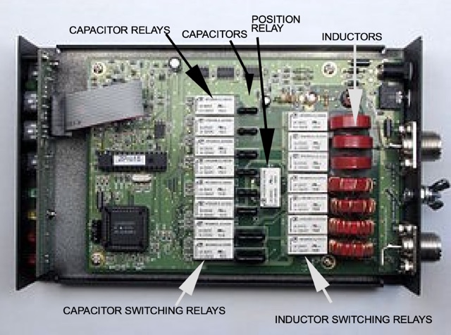 Collection of several topics on antenna tuners and their performance. Why use an antenna tuner? How does an antenna tuner…tune Does an antenna tuner fool the radio? Will an antenna tuner waste power? Can an antenna tuner help get more power to the antenna?
 -
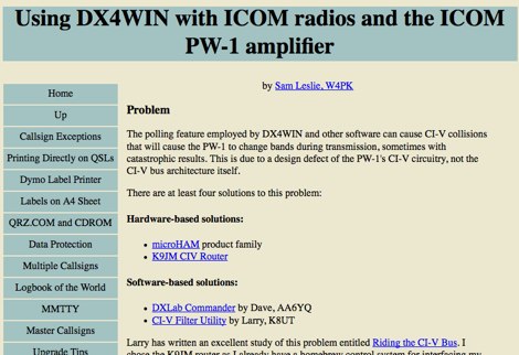 Using DX4WIN with ICOM radios and the ICOM PW-1 RF power amplifier
 -
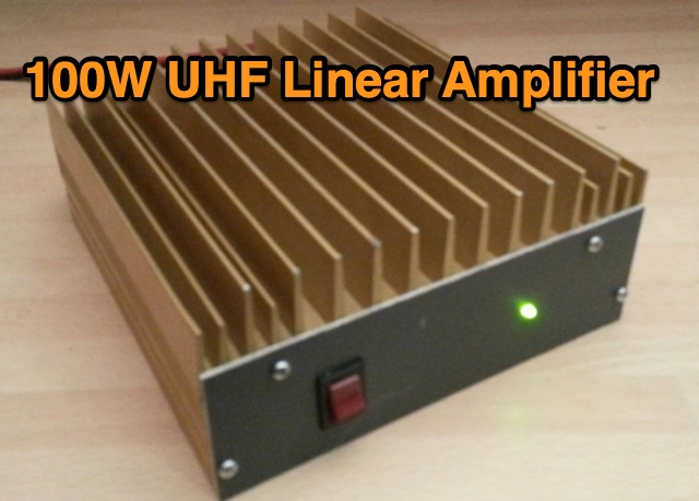 This page details my building of a 100 Watt Power Amplifier for the 432 MHz Band based on two Motorola MRF646 transistors taking inspiration by Carlo Gnaccarini VK3PY, formerly VK3BRZ
 -
 A distance of 1/8 lambda between the antenna and the vehicle roof is suggested for optimal performance, with slight adjustments possible to lower the take-off angle for terrestrial contacts. This resource details the adaptation of an _Eggbeater_ antenna for mobile use, specifically for VHF operation, leveraging the car's metal roof as a ground plane. It illustrates the mounting method, repurposing a magnetic ski carrier base, and describes the integration of coaxial relays for polarization reversal, a feature also applicable to UHF versions as discussed in "_Eggbeater Antenna VHF/UHF – Part 2_". This mobile configuration proves effective for satellite communications, such as through the International Space Station (ISS), while also maintaining strong performance for land-based radio contacts. The inclusion of switches with indicator lights for VHF and UHF polarization control, powered by the vehicle's battery, highlights practical considerations for field deployment. The system's adaptability for portable operations underscores its versatility beyond fixed mobile installations.
 -
 The DX FT8 is a compact, multiband tablet transceiver designed for FT8 digital mode enthusiasts. Supporting five or seven HF bands, it integrates an STM32F746-based touchscreen interface for standalone operation, eliminating the need for a PC. The latest firmware (v1.9.2) adds SOTA/POTA calling and free-text messaging. Its efficient power design, unique RF amplifier, and 3D-printed case enhance portability. Open-source firmware and community-driven development make it a versatile choice for portable FT8 operation, ideal for SOTA, POTA, and travel use. DX FT8 TRANSCEIVER PROJECT is a collaboration between Charles(Charley)Hill, W5BAA and Barbaros(Barb)Asuroglu, WB2CBA.
 -
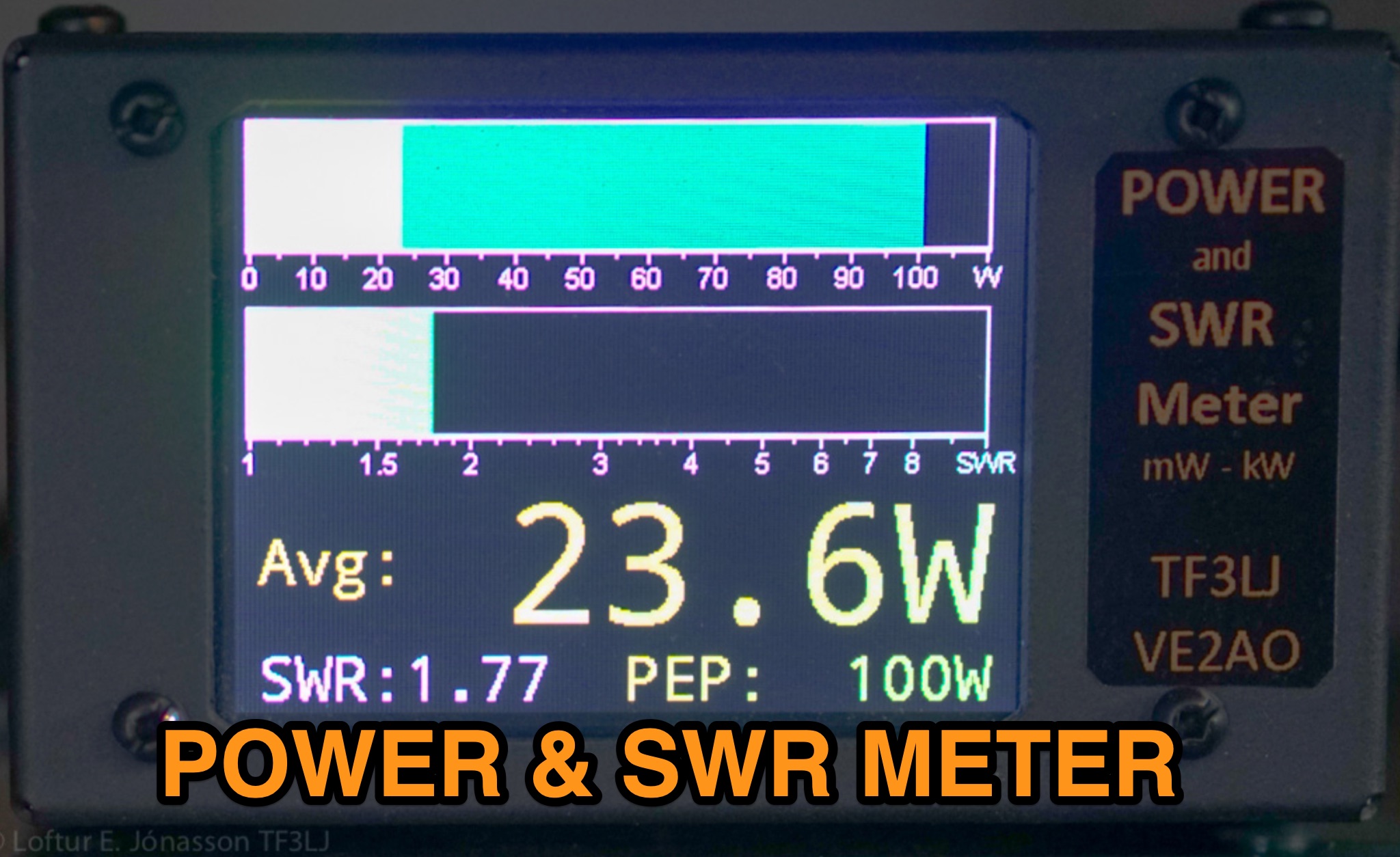 This page describes an update to a project for a Power and SWR Meter for ham radio operators. The update includes a more powerful microcontroller, increased sampling rate, and improved display options. It explains how to use the new components and provides detailed instructions for building the updated meter. The page also offers alternative display options and includes the full source code for the firmware. Overall, this update enhances the functionality and performance of the Power and SWR Meter project, making it more versatile and user-friendly for hams looking to measure RF power and SWR in their radio setups.
 -
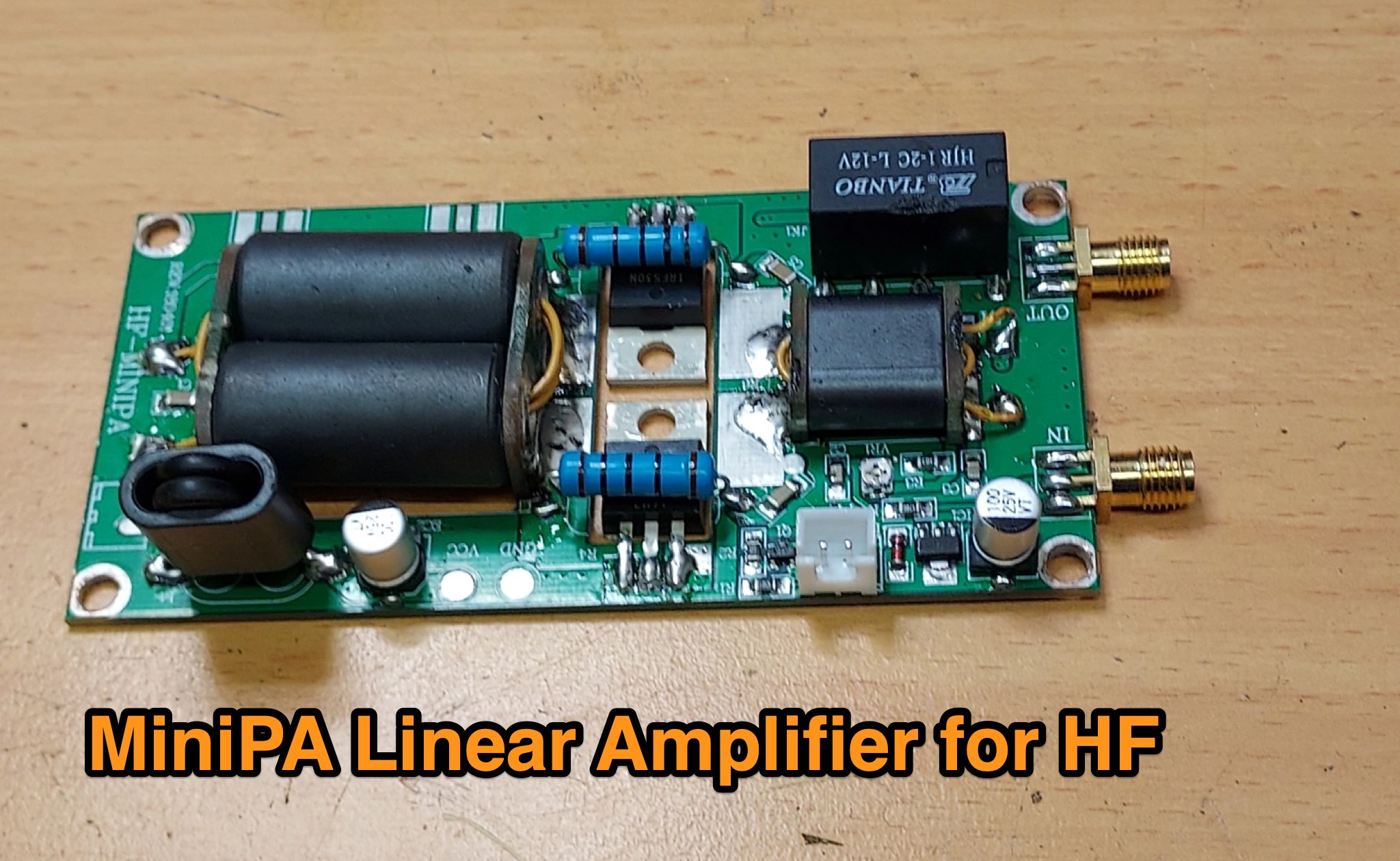 The MiniPA Linear Amplifier for HF page discusses the popularity of QRP for HF among ham radio operators, such as those using the Yaesu FT818 or low power SDR transceivers. It explores the use of cheap kits from eBay or Chinese suppliers to build a 70-100W SSB amplifier using IRF530 MOSFET transistors. The article provides a review of the MiniPA design, including its features, components, and assembly process. It also highlights the importance of using a heatsink and forced air cooling for optimal performance. This page is useful for hams looking to enhance their HF rig with a budget-friendly amplifier.
 -
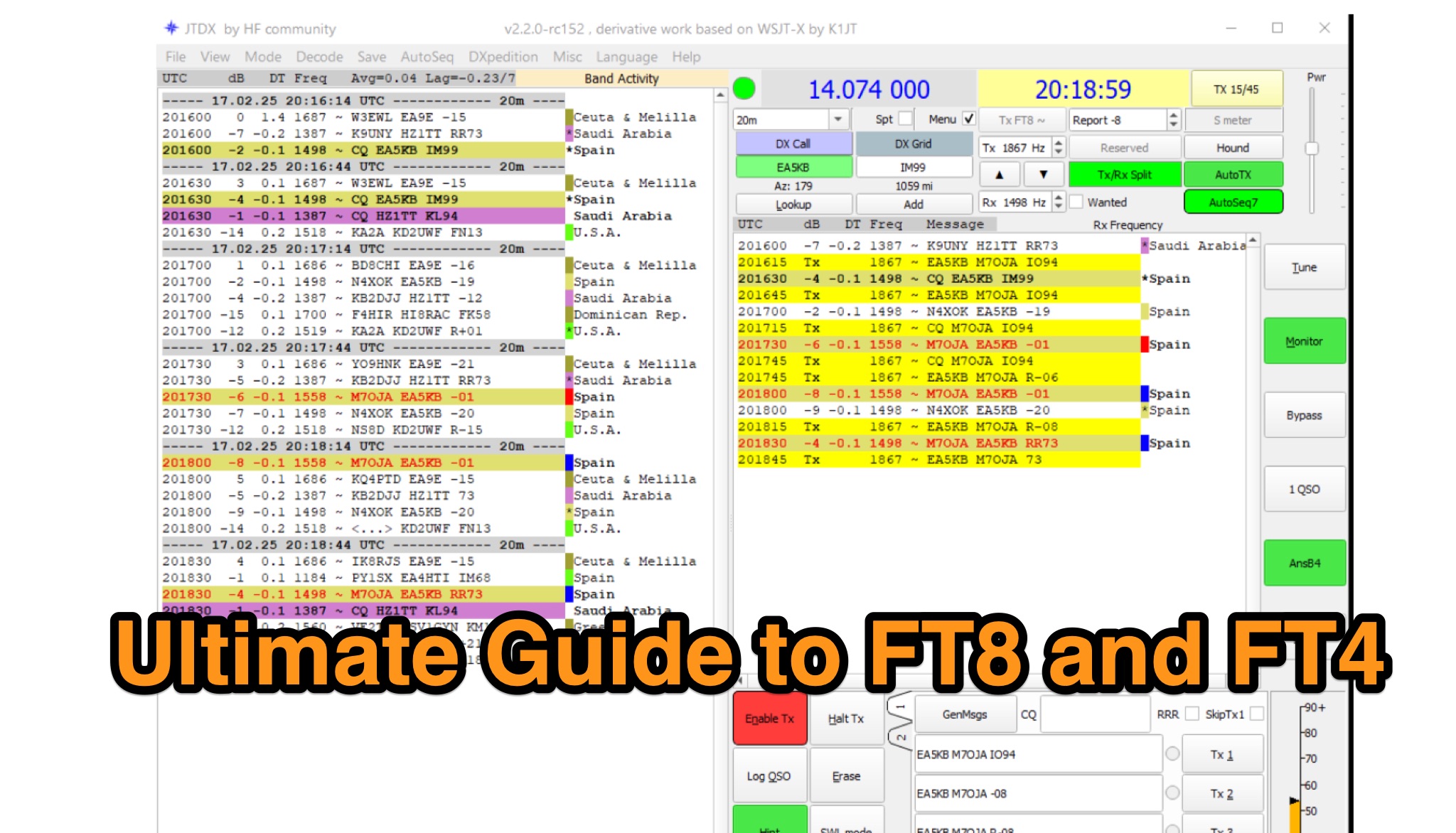 Learn all about FT8 and FT4 digital modes in ham radio. Discover how to configure software to use these powerful modes for making contacts even in poor conditions. Find out how to hunt for awards and view instant statistics of your transmissions. Explore the benefits of using digital modes such as FT8 and FT4 for enhancing your ham radio experience.
 -
 An article by MicroHam on using the Icom PW-1 RF Power Amplifier safely and with non-Icom transceivers.
 -
 Constructing a directional antenna for VHF operations, particularly for 2-meter band contests or local communication, often involves balancing performance with ease of build. The Moxon rectangle, a compact two-element beam, offers a good front-to-back ratio and gain in a smaller footprint compared to a Yagi, making it suitable for portable or temporary setups where space is limited. This design typically uses a driven element and a single reflector, bent into a rectangular shape to achieve its unique radiation pattern. The article details the construction of a 2-meter Moxon antenna, specifically for 144 MHz, utilizing readily available materials like PVC pipe for the frame and copper wire for the elements. It outlines the dimensions for the driven element at 970mm and the reflector at 910mm, with a spacing of 140mm between them, and a 50mm gap at the element ends. The feedpoint is a direct 50-ohm connection, simplifying matching requirements. The project includes a parts list, a basic diagram illustrating the element layout and dimensions, and photographs of the completed antenna. The author notes the antenna's performance during a QRP contest, achieving contacts up to 100km with 5 watts, demonstrating its effectiveness for low-power VHF work.
 -
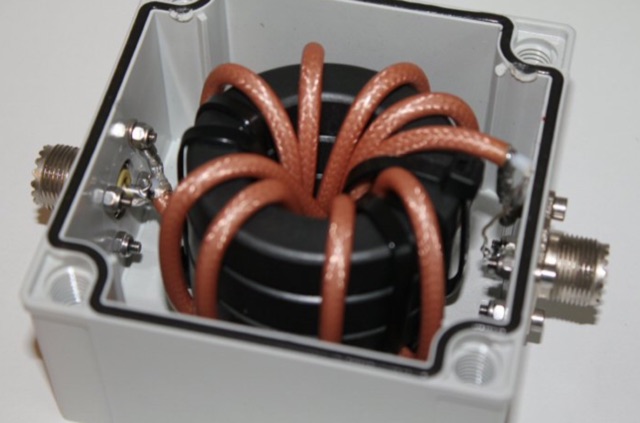 Home brewing a high performance, high power common mode choke for HF bands
 -
 Communications Equip. & Military, Harris Radios parts, test equipment, power supplies, RF parts online dealer
 -
 Paul McMahon presents a compact VSWR meter designed for QRP portable use, ideal for SOTA operations with rigs like the FT817. The device, constructed from readily available components, employs a simple resistive bridge for wideband performance from 1.8MHz to 52MHz, with diminishing accuracy at higher frequencies. Key features include no need for external power, simple calibration, and operation with low power levels. The design, detailed with parts lists, schematics, and construction guidelines, ensures a 2:1 worst-case VSWR to protect transceivers during antenna matching. Calibration points are set for accurate VSWR readings at various loads.
 -
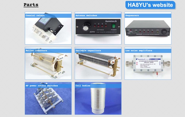 HAM-made engineering products supplies and produces coaxial relays, antenna switches, sequencers, roller inductors, variable capacitors, low noise preamplifiers, RF power rotary switches and coil bodies.
 -
 Operating an amateur radio station effectively requires reliable coaxial cable to minimize signal loss between the transceiver and antenna. SIVA Cavi, an Italian manufacturer, produces a range of coaxial cables, including specific 50 Ohm low-loss types suitable for amateur radio applications. Their product line features cables like **RG 58 SHF1**, **RG 213 SHF1**, and **RF 400 SHF1**, which are commonly deployed in HF and VHF/UHF setups. The company also offers specialized cables such as the **HF 214 UF Ultraflex**, a high-performance broadband low-loss 50 Ohm cable designed for flexibility and reduced attenuation across various amateur bands. These cables are engineered with solid or foam dielectric materials, impacting their electrical characteristics and suitability for different power levels and frequency ranges. For instance, foam dielectric cables often exhibit lower loss at higher frequencies, a critical factor for VHF/UHF operations. Beyond amateur radio, SIVA Cavi manufactures cables for digital video broadcast, offshore marine use, and fire detecting systems, demonstrating a broad engineering capability in coaxial cable technology.
 -
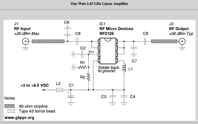 This will show you how to add a RF power amplifier to your Proxim Symphony for under $50. The cost is reduced by using the existing components on the Symphony, such as the PIN diode switch, and just inserting a higher power final amplifier. Increase the RF output power of your wireless network card to 1 Watt.
 -
 The _G3TSO_ Mobile Antenna Page details construction and tuning methods for mobile antennas operating across **10 to 160 metres**. The content describes a Hustler-based design, optimized for RF performance and vehicle speeds, featuring centre loading. For optimal operation on various bands, the loading coil placement requires clearance from the vehicle body. Antenna resonance is critical for efficient mobile operation. A mobile antenna's base impedance may be as low as 27 ohms, requiring specific matching to achieve maximum radiation, as a minimum SWR at the transmitter does not always indicate resonance or maximum output. Tuning involves physical adjustment of antenna length to achieve resonance at the operating frequency. The _G3TSO_ page outlines a tuning procedure utilizing a low-power signal source and a field strength meter to identify maximum radiation before impedance matching. Loading coil placement, either at the base, center, or top of the antenna, influences radiation efficiency and mechanical stability for mobile installations. Centre-loaded whips, such as the Hustler design, offer a compromise between efficiency and stability, often for single-band operation. Helically wound antennas, including those for **28 MHz**, may present base impedances around 17 ohms, resulting in a 3:1 SWR at resonance. Low resistance grounding at the antenna base is also specified for optimizing performance and minimizing RFI during mobile operation. DXZone Focus: Mobile | Any | Antenna Tuning | HF
 -
 eHam user's review of the Icom PW-1 RF Power Amplifier
 -
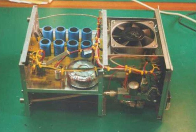 A 50 MHz stable and small power amplifier, suitable for portable and domestic use. This RF Power amplifier delivers 900W with used pair of tubes primary installed into amplifier.
 -
 The 80-meter Skyloop antenna, a top-performing HF antenna, excels in weak signal work, low-noise operation, and omnidirectional coverage. Ideal for fixed stations, it delivers strong performance at low power, outperforming many alternatives, including 80m half-wave end-fed antennas. Requiring significant space for deployment, it’s well-suited for NVIS and groundwave use. Though not portable, it’s cost-effective and durable, with minor maintenance needs. Tuning may require adjustments for optimal resonance. It’s a standout for base stations, though a lighter portable version could enhance its versatility.
 -
 The DK7ZB-Dualband-Moxon-Beam provides a compact, high-performance antenna solution for 28 MHz and 50 MHz operations, utilizing a single 50-ohm feedpoint. This design functions as a mini-beam on 10 meters, achieving a gain of **4.0 dBd** with a front-to-back ratio of _30 dB_, while operating as a 2-element Yagi on 6 meters, yielding a gain of **4.3 dBd** and an 11 dB F/B ratio. The antenna's dimensions are approximately two-thirds that of a full-size 10-meter beam, making it suitable for smaller spaces. Construction details include a parts list specifying aluminum tubes of various diameters and lengths for the reflector and radiator elements. Builders like Aleks (S54S) and Marcio (PY2OK) have successfully replicated the design, with Aleks noting the utility of bending corners during assembly. Fine-tuning is accomplished by adjusting the length of specific elements that slide into larger tubes. The feeding system incorporates a balun, with options for either 300 watts using RG188 on an FT140-43 core or 1 kilowatt using _Aircell-5_ on an FT240-43 core, ensuring versatility for different power levels.
 -
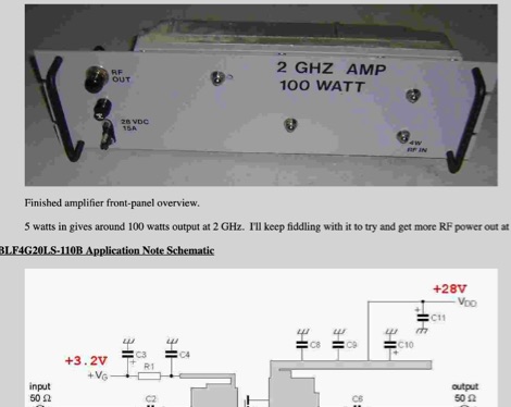 Modification to an old cellular phone base station modules, with a fairly reduced output power (10 watts or so), the stock power amplifier modules will cover the 2.3 GHz and 2.4 GHz amateur radio bands.
 -
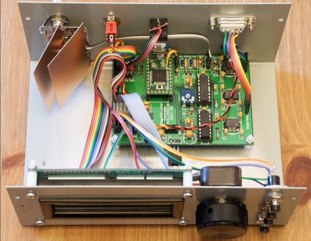 A Magnetic Loop Controller project details the construction and operation of an automatic tuning system for magnetic loop antennas, which are resonant circuits using an oversized inductor and an adjustable capacitor. The system employs a stepper motor to precisely adjust the variable capacitor, maintaining optimal resonance across the HF bands. It integrates with various transceivers, including _Icom_, _Kenwood_, and _Yaesu_ models, by monitoring the VFO frequency and adjusting the loop's tuning accordingly. The project provides comprehensive building instructions, a PowerPoint-style presentation, and the full source code for the controller's firmware, enabling hams to replicate and customize the design. The controller's firmware offers diverse functionality, including automatic frequency tracking, manual tuning, and SWR monitoring, significantly enhancing the operational efficiency of magnetic loop antennas, particularly for QRP and portable operations. The design emphasizes accurate capacitor positioning, crucial for achieving low SWR and maximum radiated power. Comparisons with manual tuning methods highlight the benefits of real-time adjustment, especially when operating across different bands or making frequent QSYs. The project's detailed documentation and available source code facilitate experimentation and modification by advanced builders, allowing for tailored performance characteristics.
 -
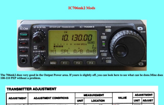 Presents two distinct hardware modifications for the Icom IC-7300 transceiver, detailing the necessary steps for each. The first modification, a _MARS_ transmit expansion, involves the physical removal of specific surface-mount diodes (D422) from the main board, enabling transmit capabilities across a broader frequency range, including out-of-band frequencies. It specifies the diode location on US versions of the IC-7300 and suggests using small diagonal cutters if a soldering iron is not preferred or available. The second modification focuses on the internal antenna tuner, aiming to provide wider impedance matching capabilities. This involves adding a **100k ohm** resistor to a designated point within the tuner circuit. The resource also briefly mentions a microphone modification for the _HM219_ and a general power increase, though without specific instructions for the latter two. It emphasizes safety precautions, such as disconnecting power and inspecting the work area.
 -
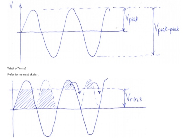 RF Power measurement using a DVM, RF Power measurement using an RF detector, RF Power measurement using an Oscilloscope and using a Spectrum Analyzer
 -
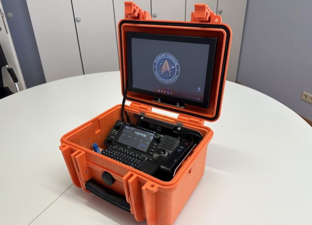 This project details the creation of a portable GoBox housing an IC705, Windows 11 PC, and Bluetooth microphone. The robust setup, enclosed in a weatherproof Hofbauer Explorer Case, ensures stability and functionality for QRP and emergency radio activities. The aluminum-mounted devices minimize RF interference, and a built-in LifePO4 battery powers the 10.1 TFT touch LED monitor, providing approximately 12 hours of use in receive mode. With a focus on grab-and-go versatility, this GoBox stands as an efficient solution for outdoor ham radio operations.
 -
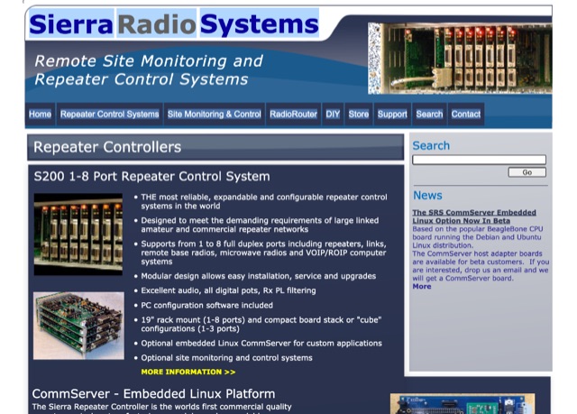 Sierra Radio Systems site controllers are used to monitor and control remote radio and equipment sites, often implemented to monitor repeater systems, broadcast equipment, solar power infrastructure, tracking rf power, temperature, voltage, current and switch closure
 -
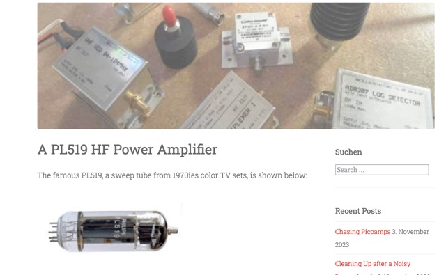 his article explores the construction of a PL519 tube amplifier, utilizing Ulrich L. Rohde N1UL's insights. Focusing on a modest 25W continuous output, the design ensures robustness with forced air cooling. The detailed breakdown covers input matching, screen grid voltage generation, bias adjustment, anode power supply, heater power supply, and monitoring circuitry, providing valuable guidance for ham radio enthusiasts.
 -
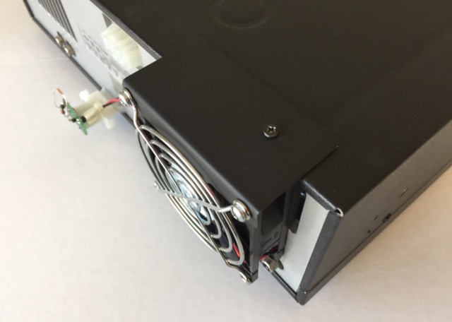 ICOM IC756 PRO II III, PS125 Fan Modifications, install an external cooling fan on the ICOM IC756 PROIII to minimize the heat on the chassis, then will perform a fan modification on the ICOM PS125 power supply to minimize the fan noise.
 -
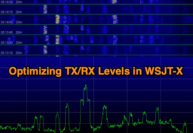 Exploring digital radio modes, the author rethinks how to adjust transmit and receive levels in WSJT-X. Despite effective communication using Yaesu's settings, a new procedure aims for better performance. For RX, set audio device levels to 100%, disable AGC, and adjust RF gain. For TX, enable "Remember power settings" and adjust power output to avoid ALC engagement. This method ensures reliable communication without signal degradation, enhancing dynamic range and minimizing noise.
 -
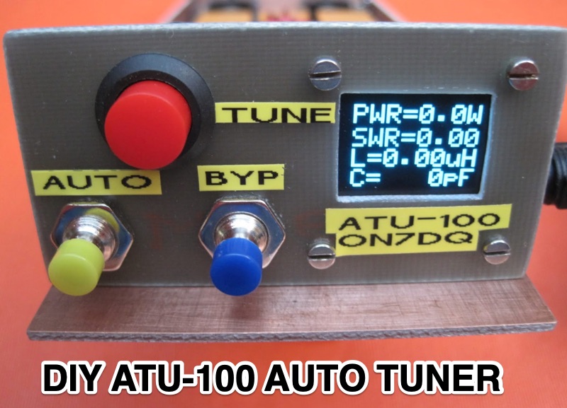 Demonstrates the construction of an **ATU-100 (N7DDC)** automatic antenna tuner, detailing the assembly process from component arrival to final enclosure. The resource covers winding the tandem match transformer, connecting the OLED display, and integrating optional control buttons. Specific attention is given to modifying the EEPROM settings for **QRP operation**, reducing the minimum tuning power to 1 Watt, and addressing potential RF interference with CPU by adding capacitors to button connections. The build log includes practical tips such as adapting RG58 coaxial cable strands for PCB mounting and utilizing a repurposed Macbook Pro cover for the custom enclosure. The author references external GitHub pages for comprehensive information, R0AEK's resources for additional details, and a video by MW0SAW for EEPROM configuration across different ATU-100 variants. Future plans involve field testing the completed tuner during SOTA or other portable activations.
 -
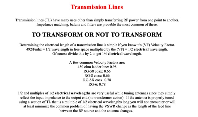 Transmission lines have many uses other than simply transferring RF power from one point to another. Impedance matching, baluns and filters are probable the most common of these.
 -
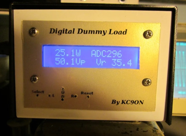 Check your RF power with an easy to read and build digital display
 -
 This is a power amplifier project for a RF 600W 1.8 MHz to 70 MHz linear amplifier including a Low Pass Filter. Projects includes schematics, pictures, PCD design, fans details, note on PA ferrite chokes and assembling instructions
 -
 This innovative antenna tuning unit (ATU) enables QRP operators to match their antennas without transmitting RF signals. Using a noise bridge technique instead of traditional transmit-and-tune methods, it achieves truly silent operation. The design incorporates an L-match network with switched inductors and variable capacitor, handling impedance matching from 3-30MHz. Operating from a 9V battery, it includes a built-in RF power meter and dummy load for QRP transmitter testing. The compact unit is particularly suitable for portable operations where minimal RF emissions during tuning are desired.
 -
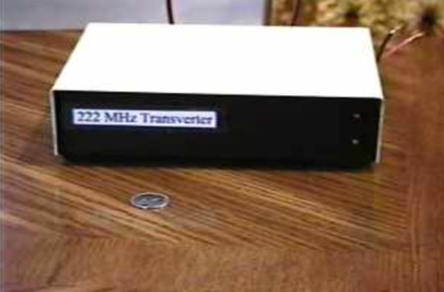 The 222 MHz Transverter project, based on Zack Lau's (W1VT) original July 1993 QEX magazine design, provides an IF of 28 MHz for both transmit and receive paths. Rick Bandla (VE3CVG) contributed supplemental notes and construction details, including modifications to achieve 10 mW output power from an initial 4 mW PEP. The design incorporates three distinct boards: a Local Oscillator (LO), a Transmitter (Tx), and a Receiver (Rx), with an estimated parts cost of just over $150 CDN, significantly less than commercial kits. Construction involves both through-hole and surface-mount components, with specific guidance on mounting MAV and MAR devices, grounding techniques, and component selection. The project details include parts lists, schematics for the LO, Tx, and Rx, and board layouts. Troubleshooting advice emphasizes sequential testing, starting with the LO, then Tx, and finally Rx, using a 194 MHz and 222.100 MHz capable FM handheld for signal tracing. Further enhancements are discussed, such as an optional Tx driver stage to boost output to 100 mW and the potential modification of a Motorola Maxor 80 PA for 222 MHz SSB/CW operation. The resource also covers practical aspects like power attenuation pads for IF radios (e.g., FT817) and considerations for enclosure design, including repurposing a Maxor 80 case. Performance reports indicate successful 70 km contacts with only 4 mW output.
 -
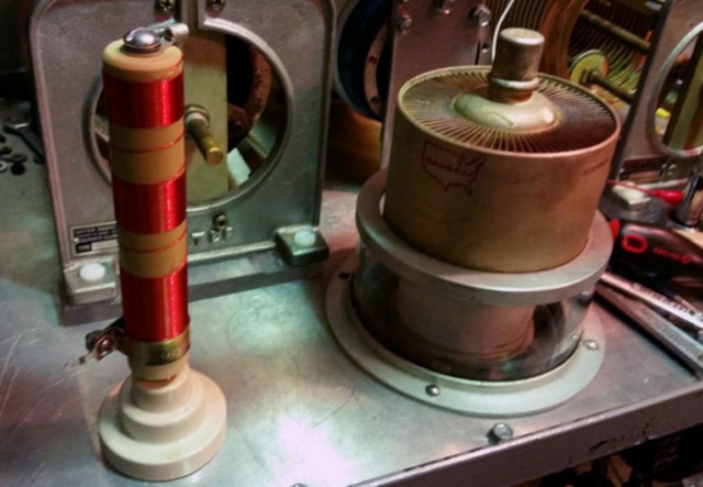 A picture gallery of a home-brew RF Power amplifier made with 3CX3000
 -
 Presents an interactive online **Moxon antenna designer** tool, enabling radio amateurs to configure and analyze lightweight Moxon antennas for HF and VHF bands. Users can specify design frequency, element lengths, wire diameter, insulation, and support height. The tool visualizes the antenna in interactive 3D graphics and generates comprehensive performance charts, including azimuth, elevation, 3D, and polarization radiation patterns, VSWR charts, antenna current diagrams, and Smith charts. It also allows selection of various ground types (e.g., very poor soil, salt water, free space) to model environmental effects on antenna performance. The designer provides insights into how physical dimensions and ground conditions influence key antenna parameters like forward gain, front-to-back ratio, and feed-point impedance, which is typically close to 50 ohms. It also includes a feature to model the effect of coaxial cable losses on **VSWR** at the transmitter end, distinguishing it from the feed-point VSWR. This helps operators understand the actual radiated power efficiency versus the apparent match at the transceiver, offering a practical perspective on antenna system performance in portable operations.
 -
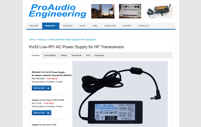 Over 1000 _Elecraft_ KX2 owners have benefited from the Kx22 Heatsink, experiencing cooler rig temperatures and higher output powers. PAE manufactures these heatsinks, along with AC power supplies for HF transceivers, remote power relays, and Ethernet relays, with all machined products manufactured in the **USA**. PAE distributes _Fair-Rite_ Mix 31 ferrite snap-it cores and toroid cores, essential for RFI suppression and impedance matching in amateur radio setups. The product line also includes commercial monitoring antennas, UQUI transformers, ULP AC power filters, and 3M conductive adhesive copper tape, catering to various station build-out and maintenance needs. The AM1 Portable Antenna Mount System and its AM1-VA Multi-Angle Adapter offer flexible antenna deployment options. PAE ensures careful packing of fragile ferrite products, with shipping cost adjustments communicated post-order for larger, heavier combinations to guarantee safe delivery.
 -
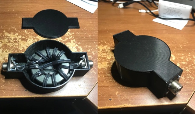 This article presents an RF Choke featuring an 11-bifilar turn winding of #14 house wire on a Fair-rite FT240-31 toroid. The choke is enclosed in a 3D-printed case from Thingiverse, though this may pose thermal concerns at higher power levels. With SWR concerns up to 30MHz, the author plans to employ two series chokes at the rig input for improved performance. This choke offers versatility for portable use, with potential mismatch resolution using an antenna tuner. Further testing is anticipated upon the arrival of new cables.
 -
 Where to buy solar panels for portable operations. PowerFilm panels and Genasun charge controllers in North America or in Europe
 -
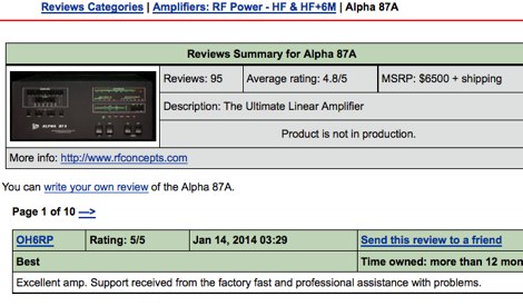 eHam reviews of the Alpha 87A RF power amplifier
 -
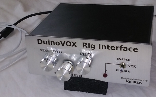 Cheap and easy to build digital modes USB interface for Ham Radio. The DuinoVOX Arduino powered digital modes USB interface for ham radio.
 -
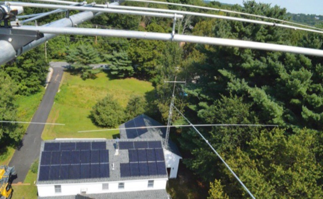 If you are having problems with RFI from Solar Panels this document from QST provides useful advice. According to this article it is possible to prevent and mitigate RF interferences, with your amateur radio equipment, by suppressing the RF either in the shack and to the solar power infrastructure.
 -
 A homebrew spectrum analyzer, the Specan, provides a crucial measurement capability often missing from the typical amateur radio shack, allowing for detailed analysis of RF signals up to 70 MHz. This double-conversion superheterodyne receiver design incorporates 112 MHz and 12 MHz intermediate frequencies, utilizing an _Si570_ as the local oscillator for fine tuning down to 1 Hz steps. It offers two resolution bandwidths: 300 KHz for broad spectrum sweeps and 1 KHz for precise close-in distortion measurements, achieving an 80 dB spur-free dynamic range at 1 KHz resolution. The project, a reboot of the classic _W7ZOI/K7TAU_ design from November 1998 QST, integrates an _Arduino_ microcontroller for controlling the Si570, managing a front-panel LCD, and communicating with a PC for spectrum plotting. This approach significantly reduces cost compared to commercial units, making advanced RF diagnostics accessible to homebrewers. The Specan can measure carrier suppression, VFO cleanliness, antenna VSWR, transmitter harmonics, and filter passband shapes, providing insights beyond what an oscilloscope or frequency counter can offer. Construction emphasizes modularity and careful shielding, with each stage built and tested individually on unetched copper clad board. The design includes detailed instructions for integrating the Arduino, building the Si570 oscillator, and aligning the various modules, often using the Specan itself for calibration. It requires a well-regulated linear power supply and can be built with common tools and readily available components, making it a practical and rewarding endeavor for those looking to enhance their RF test bench.
 -
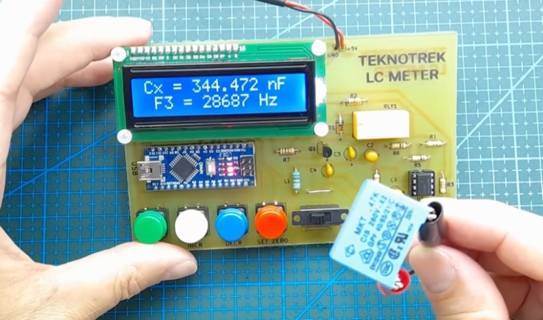 An **Arduino LC Meter** provides an accessible solution for precisely measuring inductance and capacitance values, crucial for RF circuit design, filter tuning, and troubleshooting in amateur radio applications. This project details the construction of a low-cost, accurate instrument using readily available components, making it an attractive alternative to commercial units for hams and electronics enthusiasts. The build process involves assembling a resonant circuit, integrating an Arduino microcontroller for frequency measurement, and displaying results on an LCD. Key components include an Arduino Uno, a 16x2 LCD, a 74HC14 Schmitt trigger inverter, and a few passive components. The design leverages the Arduino's processing power to calculate L and C values from resonant frequency shifts. Calibration procedures are outlined to ensure measurement accuracy, which is vital for critical RF work. The project includes schematics, a parts list, and the necessary Arduino code, enabling hams to construct a functional LC meter for their workbench.
 -
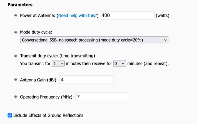 To use the RF Exposure Calculator, fill-in the form with your operating power, antenna gain, and the operating frequency. Depending on how far above ground the RF source is located, you might want to consider ground reflections too.
 -
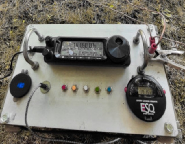 The author shares a unique experiment with a 200ft Grasswire antenna—laying wire directly on the ground. Despite inherent losses, the setup enables successful radio communication with a Kentucky station, highlighting the antenna's practicality for portable use with minimal power.
 -
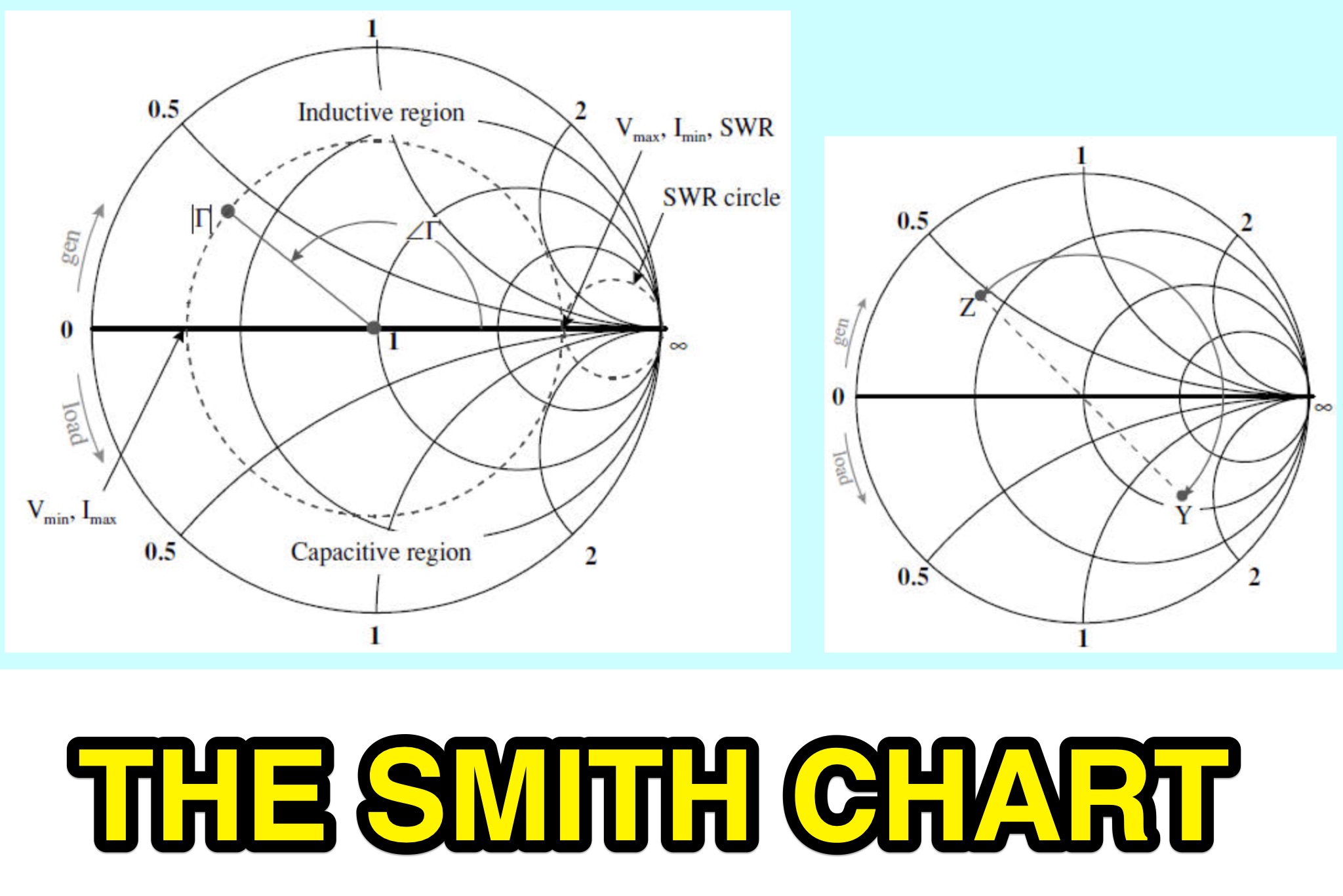 The Smith Chart, named after its inventor Phillip H. Smith, is a graphic tool used to solve transmission line problems in the field of ham radio operations. By using the Smith Chart, ham radio operators can determine the feed point impedance of an antenna, design impedance-matching networks, and optimize power transfer between a source and its load. The chart consists of resistance and reactance circles, providing a visual representation of complex mathematical relationships related to transmission line operations. Understanding and utilizing the Smith Chart is essential for hams looking to enhance the performance of their RF circuitry.
 -
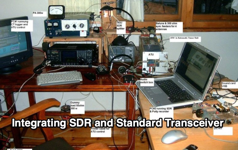 Integrating a _Software Defined Radio_ (SDR) into an existing ham radio setup involves connecting it with a standard transceiver (TRX), power amplifier (PA), and antennas. The core component is a splitter box that facilitates the connection between the TRX and the SDR, allowing for simultaneous operation without modifying existing equipment. In receive mode, the splitter ties the antenna inputs of both the TRX and a direct conversion receiver (DC RX) together. During transmission, the DC RX input is grounded via a fast telecom relay controlled by the transceiver's -SEND signal, incorporating a 10ms delay for safety. The splitter box includes a 3.7 dB input attenuator for impedance matching and acts as a protective fuse for the DC RX input. Ground loops are mitigated using common mode balun transformers, while the DC RX input is insulated with a broadband transformer. An audio switch box complements the setup, enabling users to listen to either the main transceiver, the SDR output, or both simultaneously. This configuration ensures noise immunity and safety, with the splitter housed in a screened box made from PCB material. On-air tests, such as the CQ WW 160m CW DX Contest, demonstrate the system's effectiveness, showcasing the SDR's ability to handle crowded band conditions with superior selectivity and dynamic range. The SDR's narrow bandwidth filters and waterfall display provide significant advantages, allowing operators to detect weak signals amidst strong interference. The integration of SDR with conventional radios offers enhanced operational flexibility and performance in challenging environments.