Search results
Query: qsl.net
Links: 1836 | Categories: 0
This query is too generic. Please try adding an additional term to focus your research.
-
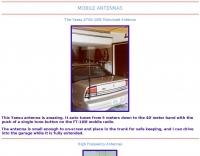 The K0RWU 75-meter mobile antenna design features a 7.5-foot overall length, incorporating a 2.5-foot loading coil wound with #20 enamel wire on a 1/2-inch fiberglass rod, subsequently covered with 1/2-inch shrink tubing to increase diameter to 3/4 inch. This configuration achieved resonance at 3965 kHz with a 5-foot stainless steel whip. The antenna integrates a matching transformer, identified by larger turns near the PL259 connector, and is constructed using a modified Radio Shack CB antenna base. Construction involves drilling and epoxying a 1/2-inch fiberglass rod into a PL259 connector, feeding #20 enamel wire through the rod, and winding 17 turns of #18 matching coil wire between the PL259 sleeve and the center feed point. The main loading coil fills the 2.5-foot rod section. The design allows the antenna to bend for garage clearance and emphasizes maintaining a 50-ohm feed impedance to prevent vehicle electrical damage. The author also discusses experiences with a Yaesu ATAS-100 motorized antenna and a 10-meter antenna project, noting issues with auto couplers and the ATAS-100's performance on 17 meters. Future modifications considered include adding a small servo for band spreading and increasing the fiberglass rod length for a 3-foot loading coil to improve bandwidth. The antenna's sharp tuning, between 3960 kHz and 3970 kHz, necessitates careful adjustment of coil turns for optimal VSWR.
-
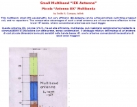 A multi band version of the EH antenna by Emilio S. Campus IS0IEK
-
 QSL extra offers QSL informations for every ardent dxer, with over 30.000 entries.
-
 Two 50 Mhz amplifiers and antenna switch
-
-
-
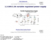 1.2-30V 1.5A variable regulated power supply
-
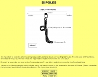 The simple dipole is perhaps the best antenna for consistent performance. Basic page on dipoles by G3PTO
-
-

-
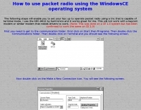 How to use packet radio using the WindowsCE operating system
-
-
 Presents the detailed construction of the _FLA25HV_ antenna, a specialized array optimized for Earth-Moon-Earth (EME) communications on the 2-meter band. This resource provides schematics and practical insights into building a high-gain antenna system capable of reflecting signals off the lunar surface, a challenging but rewarding aspect of amateur radio. It covers the mechanical and electrical considerations essential for achieving the precise pointing and signal strength required for successful moonbounce contacts, often yielding **20 dB** or more gain. Amateur radio operators pursuing EME operations require robust antenna systems and precise tracking capabilities. The FLA25HV design addresses these needs by focusing on element spacing, impedance matching, and structural integrity to withstand environmental factors while maintaining critical alignment for lunar reflections. Such systems are crucial for making contacts over distances exceeding **768,000 km**. This personal page serves as a practical guide for hams interested in constructing their own EME arrays, offering a glimpse into the technical dedication involved in pushing the boundaries of VHF/UHF propagation.
-
 Information on how to access the IRC #CQDX chat room for DXers. Also contains a live feed of DX spots directly from DX Summit.
-
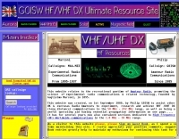 VHF/UHF DX site showing latest propagation, software, radio dealers, awards, maps etc.
-
 Details the construction of a **17-meter Moxon Rectangle** antenna, specifically engineered for mounting on a mast beneath an existing beam. The design incorporates insulated wire calculations (0.95804 x generator length) to compensate for velocity factor differences, utilizing readily available materials such as crappie poles for elements, PVC for the boom and mast, and a Budwig HQ-1 dipole connector for the 50 Ohm coax feed. The project outlines a step-by-step assembly process, including mast construction from PVC T-connectors and pipe, element fabrication from crappie poles, and securing elements to prevent droop. Initial testing demonstrated an SWR of 1.3:1 on 17 meters, achieving a 5-8 signal report into Texas with 100 watts. Subsequent reinforcement and elevation of the antenna resulted in a 15 over 9 report from Florida. Comparative testing against an 88-foot center-fed Zepp antenna indicated superior performance, with the Moxon consistently outperforming the Zepp and receiving signals the Zepp could not. A notable DX contact with JA8NFV in Hokkaido, Japan, yielded a 5-9+ signal report both ways using 100 watts.
-
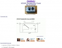 A small portable antenna tuner for HF and VHF bands by ON6MU
-
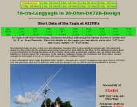
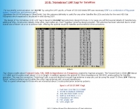 Based on DL6UW Yagi antenna's design-formula The forward gain is 13.6 dBi (about 11.5 dBd) and it's pretty small, about 1,5 m in length
-
 Satellite Tracking/Orbital Prediction Program an open-source, multi-user satellite tracking and orbital prediction program written under the Linux operating system by John A. Magliacane, KD2BD. PREDICT is free software
-
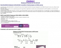 Demonstrates the construction of two distinct wideband RF preamplifiers, detailing their component requirements and performance characteristics. The first design leverages monolithic microwave integrated circuits (MMICs) such as the MAR-6, MAR-8, or PGA103, offering a broad frequency response from DC to 2 GHz with a gain of 22.5 dB at 100 MHz and a noise figure typically below 3 dB. This MMIC-based amplifier incorporates protection against power supply transients and features a 50 Ohm input/output impedance, operating from an 8-20 volt supply with low current drain. The second preamplifier design utilizes a BSX-20 transistor, providing amplification across the 14 MHz to 550 MHz range. This simpler, more economical build achieves an average gain of 12 dB at 145 MHz and a noise figure of approximately 1.1 dB. It operates from a 7-15 volt battery supply with a current draw of 6 mA. Both projects emphasize critical construction techniques, such as maintaining short RF connections, ensuring 50 Ohm impedance paths, and mounting the circuit within a shielded enclosure to optimize performance and minimize noise. The resource also discusses phantom power options for antenna-mounted preamplifiers and precautions for use with transceivers, including output protection diodes and static bleeders.
-
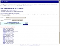 Search for your call in many of the logs hosted online, also contains links to other logs on the internet.
-
-
-

-
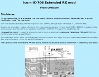 Icom IC-706 Extended receing mod From OH6LGM
-
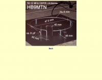 Pictures and dimensions of and HB9MTN DDRR antenna for 6 meters band
-

-
 Constructing a functional spectrum analyzer for the 0-100 MHz range presents a significant challenge for radio amateurs, often requiring specialized components and careful calibration. This project details a homebrew spectrum analyzer design utilizing common integrated circuits like the _SA605D_ FM receiver IC and _MAR-6_ MMIC amplifiers, aiming for a cost-effective solution. The design incorporates a low-pass filter, RF amplification, a voltage-controlled oscillator (VCO) for downconversion, and multiple IF stages at 150 MHz and 10.7 MHz, with a resolution bandwidth (RBW) of 15 kHz. Critical components such as the _SBL-1_ mixer and varicap diodes are specified, alongside instructions for winding inductors and tuning filters. The analyzer's performance is discussed in terms of input level limitations, specifically the 1dB-compression point and third-order intercept point, to ensure accurate measurements and prevent component damage. The _SA605D_'s logarithmic Received Signal Strength Indicator (RSSI) output serves as the detector, driving the Y-input of an oscilloscope, while a _TL084_ op-amp generates the sweep signal for the X-input. Potential enhancements include adding a step attenuator, improving front-end filtering, and implementing switchable IF filters for variable RBW, allowing for greater versatility in analyzing RF signals.
-
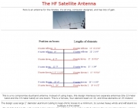 Here is an antenna for the nineties. It's strong, computer designed, and has lots of gain. It is a full size, four element beam on 10, and three elements on 15 meters
-
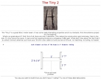 The "Tiny 2" is a great little 2 meter beam. It has some really interesting properties and it is a fantastic first time antenna project for the beginner.
-
 How to easy connect two Pc together with a Ethernet Lan
-
-
 VU2VWN project to homebrew a CW for 40 meters band
-
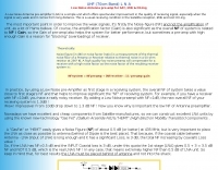 Low Noise Antenna pre-amp for SAT, EME & DX-ing
-
 Lots of projects and introductions to RDF and T Hunting
-
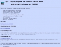 Simple program for ham radio Uses AX25 support built in Linux kernel, works in X11 graphics environment.
-

-
 This array has been in use since 1989. The SWR from 3.5 to 3.9 is below 1.5:1. The F/R of the array is 20dB average and with some signals even better.
-
 A three tube regenerodyne receiver by Gary Johanson, WD4NKA
-
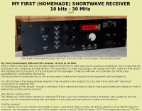 My first homemade SSB and CW receiver 10 kHz to 30 MHz
-
 This circuit provides an interface between the Yaesu 920 transceiver and IBM computer sound card which allows data transfer and control of PSK31, RTTY, KEYBOARD CW, and SSTV modes for Amateur Radio
-
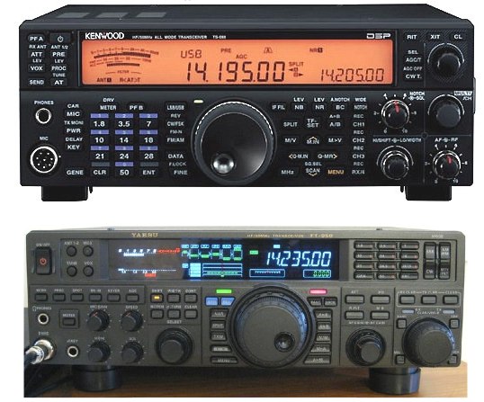 An interesting and very detailed report analysis of three populare HF+6m transceivers. Yaesu FT-950, ICOM IC-7410 and the Kenwood TS-590S by AB4OJ
-
 Applying for an FCC vanity call sign requires navigating the _Universal Licensing System_ (ULS) database to identify available call sign blocks and specific desired combinations. The process involves submitting an online application via the FCC website, ensuring all instructions are meticulously followed to avoid rejection. Typical processing time for a vanity call sign application is approximately **18 days**, after which the ULS database reflects the updated license grant. Operators often seek vanity call signs for various reasons, including aligning with a new license class, desiring a shorter call sign for CW efficiency, or simply preferring a more memorable phonetics. The resource emphasizes self-application to avoid third-party service fees, directing users to verify availability through tools like Vanity HQ. Key steps include selecting a primary call sign and several alternates, ensuring the chosen call sign conforms to FCC rules for the operator's license class. Payment can be made online or via check, with prompt submission critical to prevent application dismissal.
-
 Memory manager for ICOM IC-706 MKIIG, IC-737, IC-7000, IC-746, IC-756 ProIII, Kenwood TS-570D, TS-570DG, TS-870, TS-2000 and Yaesu FT-920, FT-1000 , FT-2000, run on windows, free by OH2KXO
-
 More links to Icom IC-746 resources on the web
-
 An RF power supply for 144 MHz schematics and instructions
-
 Web Site of CB Radio station from Vernadsky Research Station on Galindez island 140URL9909
-
 This page shows W5AJ & KD5AAU setting up a self supporting crank over tower.
-
 A site exclusively meant for the novice. Find all the information necessary to become an amateur radio operator! More India specific information.
-
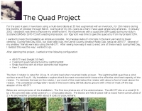
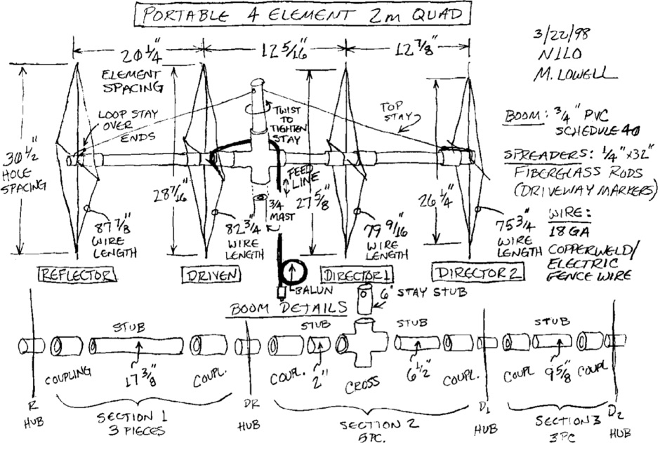 A portable 4 elements quad antenna for 144 MHz, 9 to 10 DBd forward gain, 30 DB front-to-back ratio, and 33 DB front-to-side ratio