Search results
Query: HT cable
Links: 437 | Categories: 0
-
 An Attic Coaxial-Cable trap dipole for 10, 15, 20, 30, 40, and 80 meters
 -
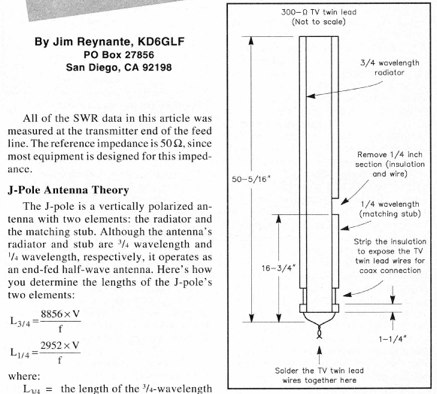 An Easy Dual-Band VHF/UHF vertical Antenna made with a TV twin lead and coax cable
 -
 The 4-band Fritzel model FD4 is a special version of a Windom antenna. It is a half-wave long on the lowest frequency, and is fed from a coax cable through a transformer inserted in the wire at one-third from one end
 -
 Sixty-four years of operating experience inform Glynn E. "Buck" Rogers Sr., K4ABT's, insights into the J-Pole antenna, which he describes as a direct descendant of the _Windom_ or _ZEPP_. His first article on the J-Pole appeared in HRC magazine in 1958, and he has since published numerous pieces in publications like CQ Magazine, consistently referring to the J-Pole as a Windom with a folded-back short section forming the parasitic element. He emphasizes that both the Windom and J-Pole are powerful multi-band antennas, performing exceptionally well at harmonics of their fundamental design frequency, and advocates for 50-ohm coaxial cable with a _BALUN_ at the feed-point to avoid RF energy losses. K4ABT details the J-Pole's features, noting its ease of erection, lack of radials, low angle radiation, greater bandwidth, and immunity to terrestrial noise. He highlights its suitability for local nets and distant repeaters, claiming more gain and durability than most ground planes, and its ability to meet stealth antenna requirements. The guide provides specific dimensions for 2-meter (145.000 to 146.000 MHz) and 6-meter (50.500 to 51.500 MHz) J-Pole antennas, including measurements for the long driven element, short tuning stub, and spacing. The construction section illustrates a modified feed technique using an SO-239 chassis-mount coax connector soldered into a copper tee, deviating from the usual hose clamp method. The author also discusses the use of _EMT_ (electrical metallic thin-wall conduit) as an alternative to copper in earlier days. He cautions against building a 75-meter J-Pole due to its impractical length, reinforcing the antenna's optimal application for VHF and UHF bands.
 -
 This resource details the fundamental aspects of deploying longwire antennas, emphasizing ease of construction and installation for shortwave listening (SWL) and broadcast reception. It covers wire gauge selection, suggesting 14 to 24 AWG for general use, with heavier gauges (14-20 AWG) for permanent outdoor installations. Guidance is provided for various deployment scenarios, including indoor setups where the wire can be run around a room, temporary outdoor installations from balconies using light 18-24 AWG wire, and permanent outdoor configurations requiring higher placement and slack for tree movement. Feeding methods are discussed, recommending coaxial cable (50-75 ohms) to mitigate man-made interference, with instructions for connecting only the center conductor to the longwire. Safety precautions are highlighted, particularly avoiding contact with power lines and conductive materials, and managing static electricity buildup by unplugging the antenna after use and bleeding off charges before connection. The article also advises against using outdoor longwires during thunderstorms or snowstorms due to static and lightning risks. Optimal height considerations are presented, advocating for the highest safe placement, ideally a couple of feet above underlying structures, to maintain free air space. The text mentions a personal setup with one end at a roof peak (20 feet) and the other at a 17-foot mast, illustrating practical deployment without strict height requirements beyond safety and clearance.
 -
 The JACK Audio Connection Kit provides a robust, cross-platform solution for routing audio and MIDI data between various software applications with minimal latency. It addresses the common challenge of directing the output of one program, such as a digital mode decoder or SDR application, into the input of another, like a logging program or audio recorder. Jack audio is a multi platform application, runs on Linux, Windows and MacOS. This virtual audio cable functionality allows for complex signal flows, enabling users to simultaneously send audio from a single source to multiple destinations and even loop it back for recording or further processing within the same or different applications. For amateur radio operators, JACK facilitates advanced configurations for digital modes, contesting, and signal analysis. It supports intricate setups where a single radio's audio output can feed multiple decoders, spectrum analyzers, or recording utilities concurrently. The API is designed for real-time performance, crucial for applications requiring precise timing and minimal delay in audio processing.
 -
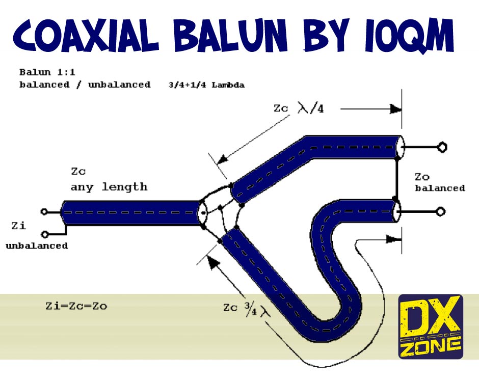 PDF article about a coaxial 1:1 balun, original concept by I4BBE using a quarter-wavelength and the three-quarter-wave adapting sections with the 50-Ohm coaxial cable by I0QM
 -
 Details the construction of a J-vertical antenna specifically for the 10-meter band, offering a practical alternative to a _Slim Jim_ design for 28 MHz. The resource outlines the use of aluminum tubing for the half-wave vertical section and coaxial cable for the quarter-wave matching section, providing specific calculations for element lengths based on frequency and coaxial cable velocity factor. It contrasts the performance of the J-vertical with center-fed dipoles and end-fed verticals, noting superior results in previous comparisons. The article further presents a more recent iteration of the J-vertical, constructed using a fiberglass pole and insulated wire, with updated dimensions for 28.8 MHz. It includes practical advice on weatherproofing connections and securing the antenna for durability against adverse conditions, referencing the survival of an original _J Vertical_ during 110 MPH winds in 1987. The SWR performance is reported as 1.1:1 at 28.6 MHz, maintaining below 1.5:1 across 28.3 to 29 MHz.
 -
 A 9 dB gain 70cm collinear antenna construction is detailed, utilizing eight half-wavelength sections of _RG58/U_ coaxial cable. The design incorporates specific calculations for velocity factor (0.66 for RG58/U) to determine precise element lengths, such as 223mm for a half-wavelength at 444 MHz. A quarter-wave radiating element of #16 solid wire, 169mm long, is added to the top, and a 160mm aluminum tube acts as a quarter-wave counterpoise at the feed point. RF choke baluns, constructed from three _FT50-43_ toroids, are positioned a half-wavelength from the feed point to mitigate common mode current. Assembly involves soldering the coax sections in series, followed by SWR testing during construction and final mounting within a ¾-inch PVC pipe. The article suggests using four half-wave elements for a shorter antenna, noting a potential slight increase in SWR, which can be mitigated with quarter-wave ground radials. The design principles and formulas are scalable for other VHF/UHF bands like 6m, 2m, or 1¼m, providing a versatile homebrew solution for enhanced gain.
 -
 This resource presents the _FCC_ Online Table of Frequency Allocations, codified under 47 C.F.R. § 2.106. The document details frequency assignments across the electromagnetic spectrum, from 0 kHz to beyond 2170 MHz, specifying allocations for various radio services including amateur, maritime mobile, aeronautical radionavigation, and broadcasting. The table is structured with columns for International Table (ITU Radio Regulations Article 5, Section IV, 2019 Edition), United States Table (Federal and Non-Federal), and corresponding _FCC_ Rule Part(s). Specific frequency ranges, such as **135.7-137.8 kHz** and **472-479 kHz**, are identified with their primary and secondary allocations, including Amateur Radio (Part 97) and Maritime Mobile (Part 80). The methodology involves direct publication of regulatory data, reflecting amendments adopted by the _FCC_ that may not yet be codified in the Code of Federal Regulations. Each entry provides the allocated service (e.g., METEOROLOGICAL AIDS, RADIONAVIGATION), relevant footnotes (e.g., 5.53, US18), and the applicable _FCC_ Rule Part. For example, the 1800-2000 kHz range is allocated to AMATEUR radio under Part 97, alongside MOBILE services. Contact information for the Office of Engineering and Technology Policy and Rules Division is provided for inquiries regarding the data. DXZone Focus: Regulatory Database | FCC Publication | Frequency Allocation | Rule Part Reference
 -
 Canada's premier amateur radio, shortwave radio, scanner, CB, marine and aircraft radio store. A complete line of acessories is also available along with full service and repair facilities.
 -
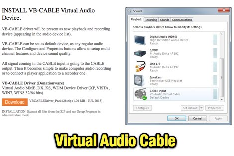 VB-Audio CABLE is a Windows Audio Driver working as Virtual Audio Cable. Will allow you to connect Audio Software together with Virtual Audio Device, to record input of streaming software. Donationware.
 -
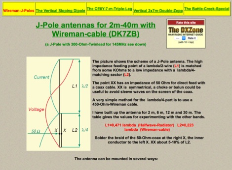 J-Poles with Wireman-cables for the quarterwave matching section, working on VHF and HF bands
 -
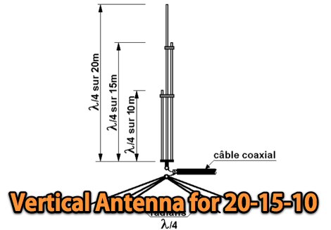 This is a vertical multiband antenna made up of several aerial elements lambda/4 length, feeded with just a coaxial cable in French.
 -
 Determining the actual need for an antenna tuner often hinges on the specific antenna and feed line configuration in use. While many hams believe a tuner is always essential, its primary role is to present a 50-ohm impedance to the transceiver, not to "tune" the antenna itself. For instance, a resonant dipole fed with _coaxial cable_ at its design frequency typically requires no tuner, as the feed line impedance closely matches the radio's output. However, operating a non-resonant antenna, or using a resonant antenna on multiple bands, frequently necessitates a tuner to manage high Standing Wave Ratio (SWR) on the feed line. The article clarifies that a tuner placed at the transceiver only matches the radio to the feed line, not the antenna to the feed line. For maximum efficiency with a non-resonant antenna, an _automatic antenna tuner_ (ATU) or a remote tuner placed at the antenna feed point is often more effective, minimizing losses in the feed line. The discussion also touches on the practical implications of SWR, noting that modern transceivers often fold back power at high SWR, making a tuner a practical necessity to achieve full output power, even if the antenna itself is not perfectly matched.
 -
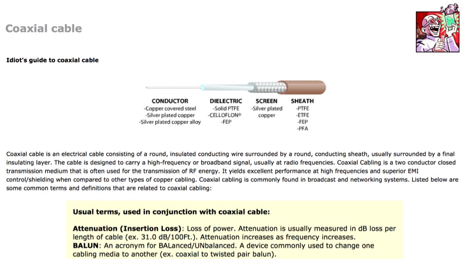 A very beginner's guide to coax cables. Characteristics, detailed comparison of typical coaxial cables, commonly used connectors, and a few words about SWR.
 -
 An efficient program to calculate dimensions of coax dipoles, or bazooka antennas considering velocity length of different coax cables. Express dimensions in feet/inch and meters/cm. Freeware by VE3SQB
 -
 This article describes how to make a quadrifilar helix (QFH) antenna easily, from inexpensive materials: uPVC plumbing pipe and RG-58U co-axial cable. A low-cost, easy-to-build Quadrifilar Helix (QFH) antenna for weather satellite reception using uPVC plumbing pipe and RG-58U coaxial cable. Unlike traditional designs requiring copper pipe and plumbing skills, this approach enables construction with basic tools and minimal technical expertise. The antenna's shorter, wider proportions favor higher elevation angles, reducing interference from horizon-level pager transmitters. Electrical connections are simplified at the antenna's apex, with the coaxial cable forming the radiating elements. Testing demonstrated consistent signal strength throughout satellite passes, proving effective weather satellite reception is achievable without precision engineering to sub-millimeter tolerances.
 -
 A switchable antenna for 80/160 meters by IK1ZOY. A new version of a 1/4L 80 m. dipole modified for use in 160 m. band. using it's own coaxial cable feeder to wrap a coil.
 -
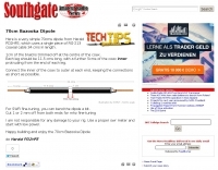 Here is a very simple 70cms dipole from Harald PD2HFE, which uses a single piece of RG-213 coaxial cable 34 cms in length.
 -
 The G3TPW CobWebb antenna design provides a compact, horizontally polarized, omni-directional solution for 20m, 17m, 15m, 12m, and 10m bands. This antenna utilizes five full-size half-wave dipoles, each bent into a square configuration to achieve omni-directional radiation without the nulls typically found in straight dipoles. The design incorporates a single 50-ohm coaxial feedline with an integrated air-core choke balun, minimizing feeder radiation and reducing EMC issues. Construction details include using PVC-covered multi-stranded copper twin cable for elements, supported by a fiberglass cross. The document specifies tapping points for impedance matching to 50 ohms on all five bands, ensuring high radiation efficiency without lossy traps or loading coils. Physical dimensions are compact, with 2.6-meter (8.5 feet) sides and a total weight of 6 kg (14 lbs), making it suitable for mounting on a 20-foot aluminum scaffold pole. Detailed instructions for assembling the junction box, including terminal strip wiring and the coaxial choke balun, are provided with photographs and diagrams. The design emphasizes a confined electric field to reduce coupling to nearby conductors, which helps mitigate TVI and makes the antenna less sensitive to mounting height or ground conductivity.
 -
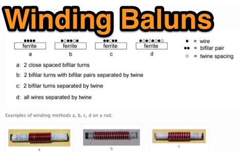 Show diagrams, winding methods and tables of some 1:1 and 4:1 baluns for 1.8 - 30 MHz suitable for use up to 200W (400W peak) on systems using 50 or 75 ohm coaxial cable input where SWR should not exceed 1.6:1.
 -
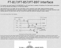 To connect up your FT-817/857/897 to a PC you have a number of options. For the serial connection you can go ahead and obtain a CT-62 from YAESU. Alternatively you can make up your box with a level converter and cable using schematic in this page
 -
 The Flower Pot Antenna project details a portable dual-band antenna primarily operating on 10 meters, with secondary resonance near the 30-meter band. Construction involves winding RG58 coaxial cable uniformly around a large plastic flower pot, approximately 70cm high with a 60cm top diameter. The design eliminates the need for radials, contributing to its compact and lightweight nature. Key construction steps include soldering the inner conductor to the shield at one end of the wound cable and connecting the wound cable's shield to the rig cable's inner conductor at the base. An LC network, comprising a variable capacitor (0-200pF) and an inductor (10 coils, 5cm diameter, 2mm wire), is inserted between the wound cable's inner conductor and the rig cable's shield. Tuning is performed with an antenna analyzer, adjusting cable length and the variable capacitor for optimal impedance on 10 meters. The antenna performs effectively when installed horizontally.
 -
 Maco Manufacturing, HF Antennas, gamma matches, cable assemblies, power supply, swr meters, watt meters
 -
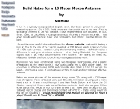 Building a directional antenna for limited space, M0MRR shares his experience constructing a 10-meter Moxon rectangle. Initially using fiberglass fishing poles and a plastic breadboard, he achieved a 1:1.2 SWR across the band with 50 watts, making contacts as far as PY2TO from the UK. The design incorporates 10-amp power cable for elements and RG58 coax with crocodile clips for feeding, demonstrating a cost-effective approach. His field observations confirm the directional properties, noting European signals fading when facing Stateside, and receiving better reports from stations in the antenna's favored direction. While not formally measured, the front-to-back ratio appears effective. The initial build was somewhat flimsy, intended for temporary deployment, but proved effective for DX. Later, M0MRR constructed a more robust 10-meter Moxon using tubular aluminum pipe, indicating an evolution in his design approach for durability. The project highlights practical antenna building for small backyards, emphasizing the benefits of a directional antenna even with modest power.
 -
 Connect your FT-100 or FT-817 to your pc with this CAT interface cable
 -
 This drawing shows a simple 10 meter wire J-pole antenna designed for 28.4 MHz. It is a vertical, end-fed Zepp-style antenna made from common materials and intended for easy home construction. The main radiating element is a straight length of stranded copper wire, either 14 or 18 gauge, cut to about 16.5 feet. At the top, the wire is supported by an insulator, allowing the antenna to be hoisted vertically. The matching section is made from 450-ohm ladder line, approximately 7 feet 9.5 inches long, and shorted at the bottom. This matching stub transforms the impedance so the antenna can be fed with coaxial cable. The feed point is tapped about 6 inches above the bottom of the stub, with the shield and center conductor connected at the proper points. A choke balun is formed with five turns of RG-58 coax in a 4-inch diameter loop to help reduce unwanted RF on the feed line. The drawing notes that this antenna has about 0 dBd gain, similar to a dipole, but offers an omnidirectional pattern and low-angle radiation when installed high. Its main advantage is practical performance, simple construction, and effective coverage for 10 meter operation.
 -
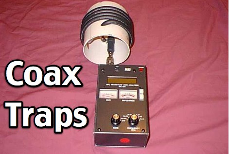 This page describes the design and construction materials W8WWV used to build a coaxial cable trap. A coaxial cable trap is a parallel resonant circuit that is usually inserted in an antenna element to enable multiband operation.
 -
 Notes on making the W2DU choke balun by placing several ferrite sleeves around a coaxial cable.
 -
 Here is a serial control (CAT) cable that plugs into the FT-857's microphone jack, freeing the CAT/Linear jack for other purposes.
 -
 A cost effective current-mode 1:1 balun can be constructed from a length of coax and a rod typically used for a broadcast antenna loop-stick, some electrical tape, cable ties, a length of PVC water-pipe and some connectors.
 -
 Constructing a compact, directional antenna for the 6-meter band presents unique challenges, especially for operators with limited space or those seeking portable solutions. This project details the build of a 50 MHz Moxon rectangle, specifically engineered for balcony or temporary mast deployment, using readily available materials from a typical hardware store. The design emphasizes ease of construction and portability, allowing for quick setup and breakdown. The antenna's dimensions are precisely calculated using _Moxgen_ software for 50.200 MHz, ensuring optimal performance. Key construction techniques include using aluminum U-channel for elements, fiberglass driveway markers for insulation, and cable ties for secure assembly. The guide provides detailed instructions for fabricating the driven element, reflector, and boom, including a clever method for creating foldable element tips for transport. Performance observations indicate a respectable front-to-back ratio, capable of reducing an S7 signal to S0 when pointed away, and a modest gain over a simple wire antenna. The design incorporates a ferrite bead choke balun at the feedpoint to mitigate common-mode current and reduce shack noise, a critical consideration for urban or apartment-based operations.
 -
 This improved multiband trap dipole introduces a new trap design and a change in trap location. The antenna features double-coaxial-cable-wound traps having lower reactance and a higher quality factor (Q) than earlier coax-cable traps by W8NX
 -
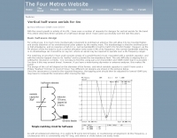 This project details three variants of a vertical half-wave antenna design for the 4-meter (70MHz) amateur radio band. The antennas use end-feeding with a parallel-tuned circuit for impedance matching to 50-ohm coaxial cable. The first variant uses suspended flexible wire for portable use, the second employs a fiberglass rod with internal wire for permanent outdoor installation, and the third utilizes aluminum tent poles for quick mobile deployment. Despite the narrow bandwidth of the matching circuit, this suits the narrow 4m FM allocation well. The design offers an effective omnidirectional radiation pattern and can be constructed with readily available materials.
 -
 manufactures and distributes HF, VHF, UHF and SHF equipment covering 10MHz. - 47.0GHz. Our products include: Wireless LAN / WAN Bidirectional Linear Amplifiers, Low Noise Preamplifiers - LNA's, RF Linear Amplifiers, Relays, Transverter Systems, Frequency Translation Systems, Downconverters, Antennas, Parabolic Dishes, Coaxial Cable, Relays, Antenna Switches, Microwave Test equipment, PC controlled Receivers, Microwave Linear Amplifiers including models for Telemetry, Wireless, and CDMA applications.
 -
 A 70 MHz Moxon rectangle antenna, built with 0.83mm enamelled copper wire and a lightweight fiberglass kite spar frame, offers a compact two-element beam solution for the 4-meter band. This design, originally for HF, scales effectively to VHF, reducing the antenna's width to approximately 75% of a half-wavelength while allowing direct coaxial cable feeding. The author, G6GVI, details the construction process, including the use of an automated design tool for precise dimensions. Initial field testing revealed a VSWR of approximately 1.3, with distinct nulls observed at 90 degrees when the antenna was mounted horizontally. The lightweight build, supported by a wooden block and U-bolt for mast attachment, makes it suitable for thinner mast sections. Further experimentation included testing with vertical polarization and considering its potential for indoor loft installation due to its relatively short major axis, offering a discreet option for urban hams.
 -
 This small window application will calculate Coax Cable loss from SWR and SWR from Cable Loss
 -
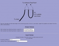 Online calculator for a 4 to 1 coax cable balun
 -
 A 10-meter J-Pole antenna, detailed in QST February 1950, offers a straightforward solution for hams operating with restricted space. This design, originally presented by W1BLR, is a **half-wave radiator** fed by a quarter-wave matching stub, providing a low-angle radiation pattern beneficial for DX. The article describes building the antenna from readily available materials like copper pipe, emphasizing its simplicity and effectiveness for **single-band operation**. The J-Pole's inherent design provides a good impedance match to 50-ohm coaxial cable without the need for an external tuner, a significant advantage for portable or minimalist stations. Its nondirectional pattern ensures coverage in all directions, making it a versatile choice for general operating on the 28 MHz band. The construction plans are clear, allowing even those with basic workshop skills to assemble a functional antenna.
 -
 RT Systems provides programming software for Windows operating systems, supporting a wide range of amateur radio transceivers, scanners, and receivers from manufacturers like Icom, Yaesu, and Kenwood. The software facilitates memory management and radio settings configuration, often surpassing OEM software in user-friendliness and functionality. Their **USB programming cables**, featuring **FTDI chipsets**, are noted for reliable operation, even in virtualized environments like Windows ARM on a Mac, where OEM cables might fail. Users report that RT Systems software simplifies the often complex process of radio programming, making it less arduous than manual entry. The availability of integrated frequency databases is a significant advantage. The software and cables are frequently cited for their long-term reliability, effective customer support, and thoughtful hardware design, which collectively address common real-world programming challenges for various radio models, including the Icom ID-880H and Anytone 878.
 -
 AEA Technology Inc. is a pioneer and leading manufacturer of RF and cable test equipment for the wireless, Telco, CATV, NMR & MRI, RFID, telemetry, aviation, commercial, military, and two-way radio industries. Produces SWR Meters, Pre Amplifiers, filters, power meters and antenna testing products
 -
 Presents the design and construction details for a VHF bicycle-mobile antenna, originally published in QST. The antenna utilizes a modified _Arrow J-Pole_ design, adapted for portable operation on a bicycle frame. Performance characteristics include a reported **1.5:1 SWR** across the 2-meter band, demonstrating effective impedance matching for typical handheld transceivers. Construction involves readily available materials, emphasizing lightweight components suitable for mobile deployment. The document provides a parts list and step-by-step assembly instructions, detailing the radiator and ground plane element lengths for optimal resonance at 146 MHz. Mechanical considerations for mounting on a bicycle are also addressed. The resource covers practical aspects of integrating the antenna with a bicycle, including cable routing and securing methods. It offers insights into achieving reliable VHF communications while operating in a mobile, low-power environment, making it relevant for field day activities or casual portable operation.
 -
 This is a picture of a schematic diagram of a multifunctional interface for Yaesu FT-8x7 Series Transceivers. It will work for Yaesu radios like FT-897 FT-857 FT-817
 -
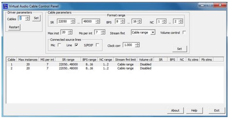 Virtual Audio Cable software allows you to transfer audio streams between applications and devices. Windows commercial software, offer a trial version limited to 3 virtual cables.
 -
 Antennas, books, rf parts, tubes,connectors and cables and many accessories at RF parts.
 -
 Antennas, base mobile scanner and vhf antenna, coax cables, coax switch, Lightning Arrestor, mounts, power supply, speakers and wattmeters
 -
 The resource details the construction and performance of a dual-band 40/30 meter _Moxon_ antenna, evolving from an initial single-band 30-meter design that failed in a storm. It specifies materials such as four 10-meter fishing rods, galvanized iron TV antenna support pipes, 1mm diameter PVC-covered copper wire, and a piece of 75-ohm TV satellite cable for feedline. The document outlines the iterative design process, including initial resonance measurements of 9.9 MHz for 30 meters and subsequent recalculations to shift the center frequency by 300 kHz using _Moxon software_. Initial testing on a roof yielded SWR readings of 1.4:1 at 7.200 MHz and 1.5:1 at 10.280 MHz. After installation atop a 30-meter tower, the final SWR measurements were 1.1 at 7.130 MHz and 1.4 at 10.230 MHz, with a notable 30 dB front-to-back ratio on 40 meters. The 30-meter performance, while good, showed a front-to-back ratio of approximately 15 dB, suggesting a slightly high resonance. The antenna's placement on a 700-meter hill, with a significant ground drop in certain directions, is noted as a potential factor in its excellent DX performance, enabling daily contacts with the USA West Coast on 30 and 40 meters with 100 watts.
 -
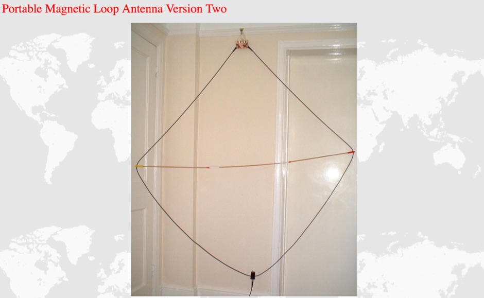 A simple multi-band magnetic loop antenna designed for 20, 30 and 40 metres, made from 16 feet of RG58 coax cable. The performance is impressive for its size but not meant to replace a Yagi. The antenna features a tuning head, matching unit, tuning capacitors, band change switch, and matching transformer. The feedpoint is at the bottom of the loop. The document provides detailed instructions on assembly and operation.
 -
 Described here is a simple omni-directional, vertically-polarized dipole for two meters. Made from coaxial cable, it can be rolled up and stored in a small container