Search results
Query: WAV output
Links: 32 | Categories: 0
-
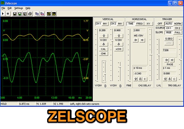 Zelscope is a Windows software that converts your PC into a dual-trace storage oscilloscope and spectrum analyzer. It uses your computer's sound card as analog-to-digital converter, presenting a real-time waveform or spectrum of the signal - which can be music, speech, or output from an electronic circuit.
-
 Determining the actual need for an antenna tuner often hinges on the specific antenna and feed line configuration in use. While many hams believe a tuner is always essential, its primary role is to present a 50-ohm impedance to the transceiver, not to "tune" the antenna itself. For instance, a resonant dipole fed with _coaxial cable_ at its design frequency typically requires no tuner, as the feed line impedance closely matches the radio's output. However, operating a non-resonant antenna, or using a resonant antenna on multiple bands, frequently necessitates a tuner to manage high Standing Wave Ratio (SWR) on the feed line. The article clarifies that a tuner placed at the transceiver only matches the radio to the feed line, not the antenna to the feed line. For maximum efficiency with a non-resonant antenna, an _automatic antenna tuner_ (ATU) or a remote tuner placed at the antenna feed point is often more effective, minimizing losses in the feed line. The discussion also touches on the practical implications of SWR, noting that modern transceivers often fold back power at high SWR, making a tuner a practical necessity to achieve full output power, even if the antenna itself is not perfectly matched.
-
 Freeware windows Wave Generator use the sound card's output as sine wave output. A built in sweep algorithm is used by audio hackers to measure frequency repsonses of their amplifiers
-
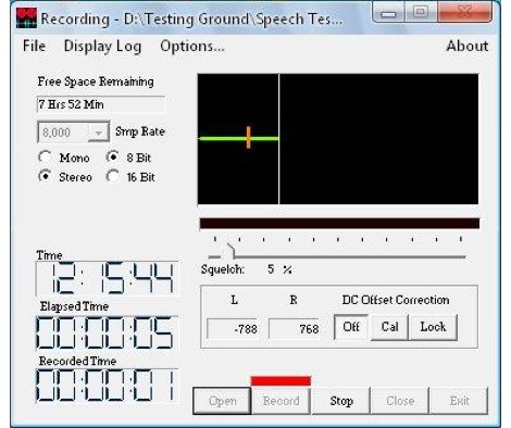 Capturing intermittent radio transmissions efficiently requires a robust audio recording solution that can intelligently manage disk space. Scanrec, a freeware Windows application, addresses this by providing a **Voice Operated Exchange (VOX)** control feature, enabling the recorder to activate only when audio signals exceed a user-defined threshold. This functionality is particularly effective for **FM communications** due to their strong squelch characteristics, minimizing recordings of static or noise. The software supports recording radio communications, air traffic control, and infrequently active channels, preserving disk space by pausing when no sound is detected. It incorporates an anti-clipping feature to ensure the beginning of audio events is not lost, a common issue with mechanical VOX systems. Output files are saved in WAV format, compatible with standard Windows Media Player. Scanrec operates on older Windows systems including Win95, Win98, NT, W2000, and XP, requiring minimal resources like a 486 PC, 4 MB RAM, and a sound card with line or microphone input. While optimized for FM, its VOX gate can be challenging to set for HF ham bands and World Band radio due to their poorer signal-to-noise ratios.
-
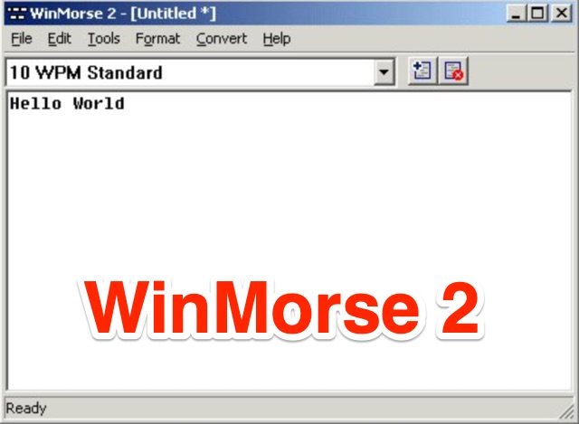 Convert text into morse code. It does this by reading text from one of three sources: the Windows clipboard, a file, or you may directly type the text. WinMorse outputs the morse code as a standard windows wav file
-
 We worry a lot about Standing Wave Ratio (SWR) in amateur radio since SWR is one indication of how well our antenna system is working. Most HF transceivers and antenna tuners have built in SWR meters. SWR is a measure of a transceiver' s output power verses the portion of that power reflected by the antenna system
-
 Signal generator using the PC soundcard to output continuous tone, CW, SSTV, AO-40 telemetry, and PSK31 test signals with variable AWGN. The program will also output to a RIFF .wav file by AE4JY
-
 PA3FWM's software defined radio (SDR) page documents his extensive hardware and software development efforts between 2004 and 2009. Initial experiments utilized a direct conversion receiver with 90-degree phase difference, feeding a PC soundcard at 48 kHz sample rate, covering 24 kHz of spectrum around a 7080.5 kHz local oscillator. This setup, similar to AC50G's QEX 2002 article, allowed for basic I/Q signal processing to distinguish signals above and below the LO frequency. Limitations included fixed crystal frequencies, 16-bit dynamic range, and narrow bandwidth. Subsequent hardware iterations aimed for enhanced performance, incorporating external 24-bit ADCs with 192 kHz sample rates, connected via 10 Mbit/s Ethernet. A **MC145170-based PLL** and programmable octave divider provided a 58 kHz to 30 MHz tuning range. The **Tayloe mixer** was employed, with differential outputs feeding a PCM1804 ADC. An ATmega32 microcontroller handled serial data conversion to Ethernet frames, though without CRC calculation due to processing constraints. Later designs integrated AD7760 2.5 Msamples/second ADCs and a Xilinx Spartan-3 FPGA, enabling direct reception of 0-1 MHz spectrum and eventually 2.5 MHz bandwidth across the shortwave spectrum. Software was refactored to use an initial 8192 non-windowed FFT for efficient high-bandwidth processing. The project culminated in a two-way QSO on 21 MHz using the developed hardware and software, demonstrating transmit capabilities with a D/A converter. The system exhibited a 2.5 MHz wide spectrum display and a zoomed 19 kHz display, capturing signals like ionospheric chirp sounders and RTTY contest activity. Challenges included noise leakage from digital circuitry and cooling for high-power dissipation components.
-
 RSCW demonstrates a Linux/Unix command-line utility engineered for **Morse code** decoding via a computer's sound card. It specifically targets the extraction of weak CW signals from noise, operating on 8-bit, 8000 samples/second audio input, typically from `/dev/dsp`. The program outputs decoded characters to `stdout`, supporting user-specified speeds in words per minute (WPM) and carrier frequencies. While effective for machine-sent signals, it exhibits a 2-second decoding lag and requires manual speed input, making it less suitable for general-purpose, real-time contest operation. The resource details the program's components, including `rscw` (the main decoder), `rscwx` (an X11 graphical auxiliary for spectrum and internal signal visualization), `rs12tlmdec` (a specialized decoder for RS-12 amateur radio satellite telemetry), and `noisycw` (a utility for generating noisy Morse signals for testing). Installation instructions involve downloading a `.tgz` file, compiling with `Make`, and requiring the FFTW library (and GTK 2.0 for `rscwx`). Performance is illustrated with a .wav file example of a 12 WPM, 800 Hz CW signal at 12 dB Eb/N0, showcasing RSCW's near-error-free decoding of a test message. The site provides command-line examples utilizing `sox` for audio conversion and `noisycw` for signal generation, inviting comparisons with other decoding software and human operators, particularly for weak signal conditions.
-
 An antenna does not have to be resonant to work, as the primary reason for resonance is to eliminate the need for an impedance-matching device. A non-resonant wire dipole fed with open-wire line and an antenna tuner can function as an effective multiband antenna. Two wires are essential for powering an antenna, ideally with a balanced configuration like a dipole fed by parallel-wire line, though coaxial cable can be used with a 1:1 balun to mitigate RF feedback on the shield. Antenna gain is achieved by shaping and aiming RF energy, concentrating it in a particular direction, as seen in beam antennas or shaped radiation patterns of wire antennas. The function of an antenna tuner is to match the transceiver's 50 Ohm output to the antenna system's impedance, which can vary widely. Wire antennas do not always require center feeding; end-fed long wires or off-center-fed dipoles (Windom antennas) can be used, often requiring a counterpoise or radial system. Dipole antennas do not need to be perfectly horizontal; their legs can be bent, inclined, or even vertical, affecting feed point impedance. Vertical antennas shorter than a half wavelength necessitate a ground system, typically comprising radial wires, with more radials generally leading to greater efficiency. A 1:1 SWR indicates an impedance match but does not guarantee a good antenna, as an inefficient antenna with a poor ground system can still show a perfect SWR while wasting RF as heat. Always using the best feed line affordable is crucial for minimizing loss and maximizing RF signal delivery to and from the antenna.
-
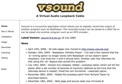 Vsound is a Linux software which allows you to digitally record the output of another program. The recorded output can be saved to a WAV file or can be transferred into another software. It's basically an audio transfer cable software.
-
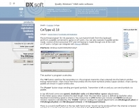 CwType v2.35 provides a dedicated terminal interface for **CW operators**, facilitating Morse code transmission from a Windows PC. Users can input characters via the keyboard or a connected paddle, supporting iambic keying. The software manages transceiver control, including PTT and CW keying, through COM or LPT ports. It offers adjustable speed, dash/dot ratio, and inter-letter spacing, with real-time speed display in LPM and WPM calculated by the "PARIS" method. The program includes features like MOX mode for automatic TX on/off, configurable weighting to compensate for transceiver element clipping, and programmable F-key macros for sending predefined text or special sequences. CwType can integrate with logging software such as AALog (V1.0.3 and later) for data transfer, and supports various character sets including English, Russian, and Swedish. A beacon mode is also available, executing the Alt-F12 macro periodically at a user-defined interval. Audio output for monitoring can be routed through the internal PC speaker or a sound card, with options for sine waveform and smooth envelope generation for SSB transmitters. The software is compatible with **Windows XP/Vista/7/8/10** and is distributed as freeware.
-
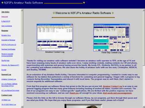 N3FJP's ARRL Field Day Contest Log 6.6.10 is a dedicated software solution for Windows 7 through Windows 11, specifically tailored for the annual ARRL Field Day event in June. This program provides essential contesting features such as duplicate checking, including partials, and a dynamic list of sections that change color upon being worked. It seamlessly interfaces with popular digital mode software like WSJT-X, Fldigi, and JTAlert via API, and supports rig control for most Elecraft, Icom, Kenwood, and Yaesu transceivers. The software also generates computer-generated CW via serial port or Winkeyer, plays wave files, and offers DX spotting capabilities. Operators can leverage its fully networkable design to allow multiple PCs to update a single log file simultaneously, enhancing club operations during Field Day. The program outputs ASCII log, dupe, and summary files for contest submission and provides real-time statistics. A quick start video is available to guide new users through the basics of the software. Registration for permanent use costs $8.99, or it can be obtained as part of the N3FJP Software Package, which includes over one hundred amateur radio programs for a one-time fee of $59.99.
-
 Generating Morse code audio files from text input is the primary function of _MorseGen v1.2_, a utility designed for amateur radio operators. The software allows users to specify the tone frequency and words-per-minute (WPM) speed for the generated CW. A key feature is its ability to create a WAVE audio file containing the Morse code, which can then be used in various applications. The program also supports repeating the generated CW sequence at user-defined intervals, making it particularly useful for creating station identification signals or beacons. The practical application of this tool extends to automated station identification, especially for repeaters or digital mode gateways that require a CW ident. By producing a standard _WAVE file_, the output is compatible with most audio playback systems and software. This functionality provides a straightforward method for integrating custom Morse code messages into existing amateur radio setups, eliminating the need for external hardware keyers for simple identification tasks. The adjustable parameters offer flexibility to match specific operational requirements or personal preferences for CW characteristics.
-
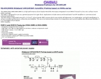 Demonstrates the construction of two distinct wideband RF preamplifiers, detailing their component requirements and performance characteristics. The first design leverages monolithic microwave integrated circuits (MMICs) such as the MAR-6, MAR-8, or PGA103, offering a broad frequency response from DC to 2 GHz with a gain of 22.5 dB at 100 MHz and a noise figure typically below 3 dB. This MMIC-based amplifier incorporates protection against power supply transients and features a 50 Ohm input/output impedance, operating from an 8-20 volt supply with low current drain. The second preamplifier design utilizes a BSX-20 transistor, providing amplification across the 14 MHz to 550 MHz range. This simpler, more economical build achieves an average gain of 12 dB at 145 MHz and a noise figure of approximately 1.1 dB. It operates from a 7-15 volt battery supply with a current draw of 6 mA. Both projects emphasize critical construction techniques, such as maintaining short RF connections, ensuring 50 Ohm impedance paths, and mounting the circuit within a shielded enclosure to optimize performance and minimize noise. The resource also discusses phantom power options for antenna-mounted preamplifiers and precautions for use with transceivers, including output protection diodes and static bleeders.
-
 Loop antennae have been used from ELF to UHF since the beginning of radiocommunications. At low frequencies, the main problem for loop antennae is to have enough sensitivity; the antenna being very small respect to the wavelength the collected energy is also small. To increase the output level the loop may be made resonant, so loosing it%u2019s intrinsic aperiodic characteristics.
-
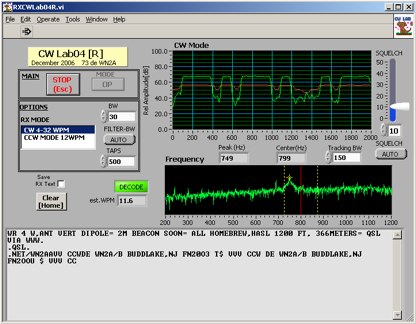 Deciphering weak or noisy **CW** (Continuous Wave) signals often presents a challenge for amateur radio operators, particularly in contest environments or during DXpeditions. CWLab04X addresses this by providing a software solution that leverages **DSP** (Digital Signal Processing) capabilities of a soundcard to decode Morse code. It functions as both a receiver and a sender, supporting traditional CW and a unique "CCW" mode designed to enhance copyability of signals struggling against high noise floors. The program offers two installation methods: a Windows-specific installer for straightforward setup or a zipped package compatible with Windows and Linux systems running Wine. Users must first download and review the accompanying PDF documentation, CWLab04.pdf and CWLab04_Hardware.pdf, which detail the software's operation and the necessary soundcard interface circuit. The hardware PDF outlines a direct connection from the receiver audio output to the soundcard input, with optional conversion of the soundcard output for hard-keying or microphone input. CWLab04X is intended as an operational aid rather than a replacement for skilled human copy, particularly highlighting the effectiveness of its CCW mode in adverse signal conditions. The software was last revised in April 2009, with installation requiring the LV Runtime 602.
-
 The Voice of America (VOA) website serves as a primary digital platform for its international news and information services, broadcasting in 44 languages. The resource presents a wide array of current events, geopolitical analyses, and cultural reports, reflecting a global perspective on news originating from the United States. Content spans various regions, including Africa, Asia, the Middle East, and specific country-focused reports from VOA's language services, such as VOA Uzbek, VOA Kurdish, and VOA Russian. The site features top stories, special reports, and sections like "All About America" and "VOA Explains," providing in-depth context on US-related topics and global issues. The VOA platform offers a continuous stream of updated news articles, covering political developments like government shutdowns, diplomatic relations, and international conflicts, alongside social and economic issues. It also includes sections for "Worth Watching" videos and "From VOA's Language Services," highlighting the breadth of its multimedia output. The content is designed to inform a worldwide audience, often presenting multiple perspectives on complex international events and US foreign policy, making it a significant reference for those monitoring global news and shortwave broadcast content.
-
 A 50-ohm generator feeding a 50-ohm line connected to a _quarter-wave transformer_ (150 ohms) terminated in a 450-ohm load is analyzed to understand transient behavior. The paper meticulously tracks voltage and current waves, reflection coefficients, and power levels through a sequence of events, starting from quiescent conditions. It details how incident and reflected waves combine and interact at impedance discontinuities, illustrating the dynamic changes in impedance and SWR at various points in the system. The analysis reveals that the impedance at the interface between the 50-ohm line and the 150-ohm transformer changes from 150 ohms to **64.3 ohms** after the first reflected wave arrives. Subsequent reflections cause the impedance to asymptotically approach 50 ohms, reaching **53.22 ohms** after five wave terms. The study also examines the generator's reaction to transient SWR changes, noting that a 3:1 SWR can temporarily reduce generator output to 0.75 watts, but these effects are temporary and diminish as the system approaches steady-state conditions.
-
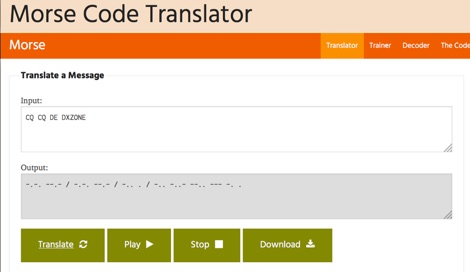 One hundred and fifty words per minute (WPM) is a configurable speed setting in this online Morse code translator, which facilitates bidirectional conversion between plain text and **Continuous Wave (CW)**. Users can input text to generate corresponding Morse code, or enter Morse code using dots and dashes to receive a text translation. The tool supports various alphabets, including Latin, Cyrillic, Ukrainian, Hebrew, and Arabic, broadening its utility for international communication. The platform offers multiple output methods for the generated Morse code, including audible playback, visual flashing, and device vibration. Advanced configuration options allow for precise control over the sound's pitch (frequency), volume, and overall speed, including a **Farnsworth speed** setting. This flexibility enables users to customize the learning or communication experience to their specific needs. Additional features include the ability to save the generated Morse code audio as a WAV file and to create shareable links for messages, which can be sent with or without the accompanying text. The interface is entirely web-based, built with HTML5 and JavaScript, ensuring broad compatibility across modern browsers.
-
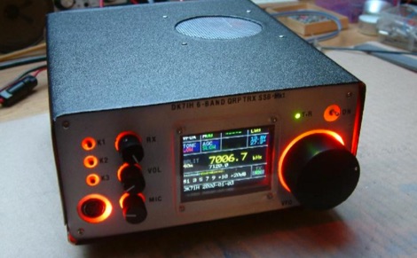 An SSB radio for the HF bands will be presented. Featuring 12 to 20 Watts of output power (depending on DC supply), full DDS frequency generation, covering 6 major frequency bands (1.8, 3.5, 7, 14, 21 and 28 MHz) within the short wave amateur radio spectrum. The rig also features colored LCD and front panel backlight.
-
 Ten essential tips and truisms for understanding HF antenna: Non-resonant wire dipole antennas fed with open-wire line and an antenna tuner can function effectively as multiband antennas, as detailed in "The Classic Multiband Dipole Antenna" by WB8IMY in March 2004 QST. Coaxial cable, unlike balanced parallel-wire feed lines, can cause RF to travel on the outer shield braid, leading to RF feedback to the station; a 1:1 balun at the dipole center can mitigate this by isolating the unbalanced coaxial feed line. Antenna gain is achieved by shaping and directing RF energy, with beam antennas concentrating power in a specific direction, and wire antennas also exhibiting shaped radiation patterns. An antenna tuner's primary role is to match the transceiver's 50-ohm output to the antenna system's impedance, allowing modern transceivers to deliver full power. Wire antennas do not always require center feeding; end-fed long wires or off-center-fed dipoles (like the Windom) can be used, though they often necessitate an antenna tuner and a counterpoise or radial network. Dipole antennas do not need to be perfectly horizontal; their legs can be bent or inclined, which affects feed point impedance and may require SWR experimentation with coaxial feed. Vertical antennas shorter than a half wavelength require an efficient ground system, typically comprising elevated or buried radial wires, with more radials generally leading to better efficiency. A 1:1 SWR indicates an impedance match but does not guarantee antenna efficiency; an inefficient vertical antenna with a poor ground system can show a low SWR while wasting most RF as heat. Investing in high-quality, low-loss feed line, especially coaxial cable, is crucial for maximizing RF signal transfer and overall antenna system performance.
-
 A 17 3/4-inch radiating element and 18 3/4-inch ground plane radials form the basis of this quarter-wave ground plane antenna for 2 meters FM. The design, attributed to AA1PG, utilizes a panel-mount SO-239 UHF connector and three lengths of #12 copper wire, with a total material cost estimated at $3.00. Construction involves soldering the elements directly to the SO-239, emphasizing thorough solder flow for robust connections. Recommended feedline includes _RG-8X_ for longer runs, with _RG-58_ acceptable for shorter lengths, cautioning against _RG-174_ for VHF applications due to high loss. The antenna is designed for elevated deployment, such as in trees or on roof gables, to maximize line-of-sight propagation. It aims to improve repeater access compared to typical rubber duck antennas, even with low power output.
-
 A synthesized 2.3 GHz Amateur Television (ATV) transmitter design, conceived by Ian G6TVJ, is presented, targeting broadcast-quality video performance on the 13cm band and extending up to 2.6 GHz. The core of the design utilizes a commercial Z-comm Voltage Controlled Oscillator (VCO) that tunes from 2.2-2.7 GHz, providing a +10 dBm output and simplifying RF alignment. This VCO's stability, originally intended for narrowband applications, readily accepts high-frequency video modulation, contributing to the transmitter's robust performance. The exciter stage, incorporating a Mini Circuits VNA 25 MMIC amplifier, boosts the signal to +16dBm, while a Plessey SP4982 prescaler divides the output frequency for the synthesizer. The synthesizer employs a Motorola MC145151 CMOS parallel IC, favored over the common Plessey SP5060 for its superior video modulation characteristics and ease of programming without microprocessors. This choice addresses issues like LF tilt and distorted field syncs often seen with SP5060 designs, particularly when operating through repeaters or over long distances. The MC145151 divides the signal further, enabling precise frequency stepping, with programming handled by EPROMs for channel selection and LED display. The loop filter network, critical for video integrity, was developed through experimentation to prevent the PLL from reacting to video modulation, ensuring a clean transmitted picture. The transmitter incorporates a Down East Microwave commercial power amplifier module, delivering approximately 1.6W output, driven by the exciter through a 3dB attenuator. Construction involves surface-mount SHF components on micro-strip lines etched onto double-sided fiberglass board, housed within a tinplate box. The design boasts no AC coupling in the video path, preserving low-frequency response, a common failing in other ATV transmitters. Performance tests with a 50Hz square wave revealed no LF distortion, and a calibrated "Pulse & Bar" signal showed a near 100% HF response, demonstrating its capability for high-quality ATV transmissions.
-
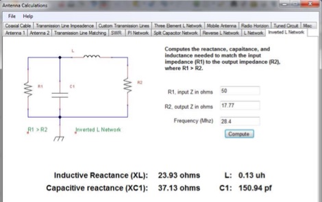 The program consists of tabbed pages for various antenna and transmission line calculation. You can compute the values for an inverted L network that will allow you to match the 50 ohm output of the radio, or you can compute the necessary length in the units of choice for a 5/8 wave vertical for 10 meter band.
-
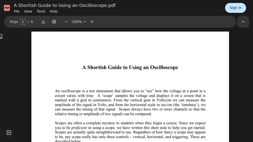 The "Shortish Guide to Using an Oscilloscope" elucidates the fundamental operation of oscilloscopes, detailing the purpose and function of vertical, horizontal, and triggering controls. It explains how vertical gain in Volts/cm and horizontal scale in sec/cm enable measurement of signal amplitude and timing, respectively. The resource differentiates between analog and digital scopes, noting that digital scopes often feature "soft" controls and are inherently storage scopes capable of capturing non-repetitive events. The guide dedicates a significant section to the critical role of oscilloscope probes, emphasizing their design to transmit waveforms without distortion or added noise. It explains the concept of a 10x passive scope probe, which reduces circuit loading by a factor of ten and eliminates waveform distortion through probe compensation, typically adjusted using a 1kHz square wave reference output. The document also provides practical advice on probe care and compensation procedures. Further sections address grounding considerations, explaining how a scope measures voltage relative to its chassis ground, which is tied to the protective earth. It offers troubleshooting steps for a blank screen and outlines essential good practices, such as checking input gain and probe attenuation, while explicitly warning against misusing probes or connecting the ground clip to mains voltage.
-
 The ZS1J/B beacon operates on 28.2025 MHz with 5 Watts output to a half-wave, end-fed vertical antenna, initially installed in 1977 as ZS5VHF near Durban. The 10-meter transmitter is a modified 23-channel CB radio, and the identification keyer uses a diode matrix unit with TTL ICs from the same era. After relocation to Plettenberg Bay in 1993, the beacon has been in continuous service, with additional QRP transmitters later installed for other bands. In 1994, a single-transistor, 80-meter, 0.5-watt QRP transmitter with a half-wave dipole was added on 3586 kHz, followed by a 160-meter, 0.5-watt unit on 1817 kHz. A 30-meter, 0.5-watt transmitter was installed in 1996, operating on 10.124 MHz. In 2002, a 40-meter QRRP beacon on 7029 kHz, with an output of 100 microwatts, achieved DX reports up to 1100 km from ZS6UT in Pretoria. Best DX reports for the 80m and 160m beacons came from 9J2BO.
-
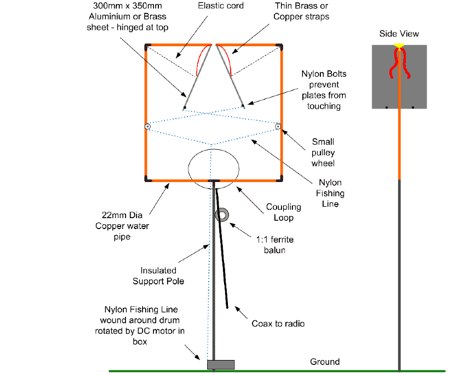
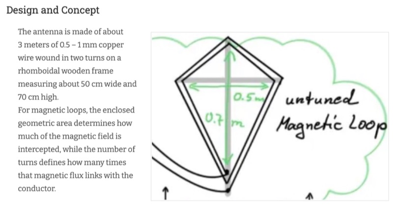 This resource details the construction and performance of a compact broadband magnetic loop antenna designed for portable receiving applications with devices like the _ATS MiniRadio_. The antenna utilizes approximately 3 meters of 0.5–1 mm copper wire wound in two turns on a rhomboidal wooden frame, measuring 50 cm by 70 cm. It connects via a modified 9:1 unun, where the primary center tap is isolated from ground to improve common-mode noise rejection. The design provides untuned operation across a frequency range from the longwave band up to approximately 25 MHz. Performance characteristics include observable directivity for noise suppression and the ability to connect directly to a radio or via a 50 coaxial cable for remote operation. The article specifies the unun's 3:1 turns ratio and its SMA output for connectivity. The methodology focuses on practical construction and observed reception quality.
-
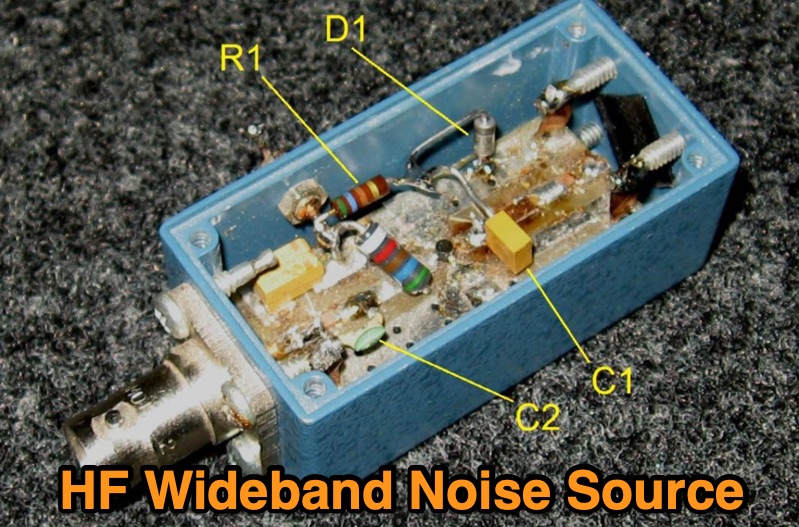 Details the construction of a **wideband noise source** for HF filter alignment, specifically targeting transceivers such as the Elecraft K2. The design modifies a Down East Microwave (DEMI) MMIC amplifier board, part number MMICPCB, by integrating a 1N4735A zener diode, 560-ohm resistors, and 4.7 nF, 10 nF, and 22 µF capacitors. This modification enables the board, originally configured for a MAR-6 MMIC (with MAR-1 as an alternative), to generate noise suitable for procedures like the K2's "CAL FIL" function. The resource provides a **schematic** and a comprehensive bill of materials, including specific component values for replication. It outlines the practical steps involved, such as removing the input connector and integrating the new components into the existing MMIC amplifier board layout. The output is optimized for wideband HF applications, ensuring compatibility with various filter alignment tasks. This project focuses on practical implementation, demonstrating how to repurpose readily available components for a critical test instrument. It offers a cost-effective alternative to commercial noise sources, leveraging existing amateur radio hardware for enhanced station maintenance and performance.
-
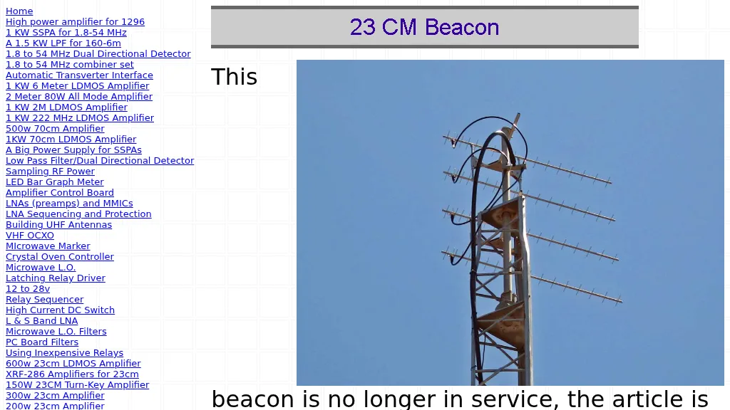 The W6PQL 23cm Beacon Project describes a **1296 MHz** beacon designed for microwave propagation studies and equipment testing, capable of 30 watts output. It utilizes a PIC 16F628A microcontroller to generate CW and FSK keying for a crystal oscillator, followed by a series of frequency doublers and triplers to reach the target frequency. The final power amplification stage employs a Mitsubishi M57762 module, providing a robust 10-watt RF output. The design emphasizes stability and reliability for continuous operation, with the microcontroller code, written in assembly, provided for customization of the beacon's callsign and message. Originally located in CM97am and aimed at 140 true, the beacon used four 4-foot Yagis stacked vertically for a total ERP of 3kW. The article includes schematics, parts lists, and construction notes to guide builders, along with antenna pattern measurements. Although the beacon itself is no longer in service as of August 2010, the detailed documentation remains a valuable reference for amateur radio operators interested in building similar **microwave** projects or understanding beacon operation.
-
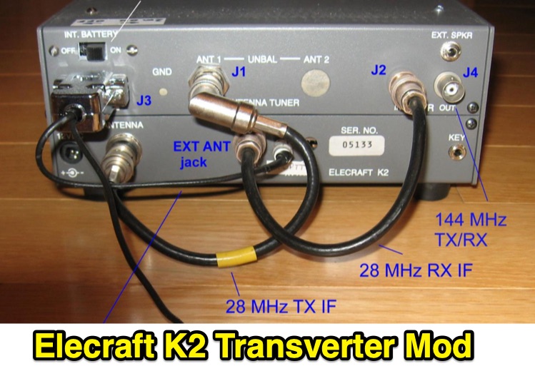 Demonstrates the conversion of an _Elecraft K2_ QRP HF transceiver to serve as a 2-meter Intermediate Frequency (IF) rig for microwave transverters, addressing the obsolescence of older _Yaesu FT-290R_ units. The project integrates a _DEMI 144-28DC_ transverter board, configured for a 28 MHz IF, and details the necessary modifications to the K2, including the installation of the K160M module for a separate receive-only antenna input and the KSB2 SSB module for voice operation. The modified K2 provides a stable 1-watt output for the 2m IF, utilizing the QRP antenna jack for transmit and the K160M input for receive, with a custom PTT control circuit. The article outlines the physical integration and electrical interfacing, including the design of an internal attenuator for the 28 MHz IF output and a control circuit for the 144 MHz interface. It also covers the construction of a medium power amplifier using an _MGA-31389 MMIC_ to boost the 2m output to 100 mW, matching the original FT-290R performance. Performance measurements for the amplifier, including output power versus input power and gain versus frequency, are presented. The project culminates in a fully integrated solution, with schematics and photos illustrating the internal wiring and external connectors. The modified K2, dubbed the "K290R," was successfully deployed in the 2017 _ARRL 10 GHz and Up Contest_ with a _Kuhne 10 GHz_ transverter, demonstrating reliable operation for CW and SSB modes.
-
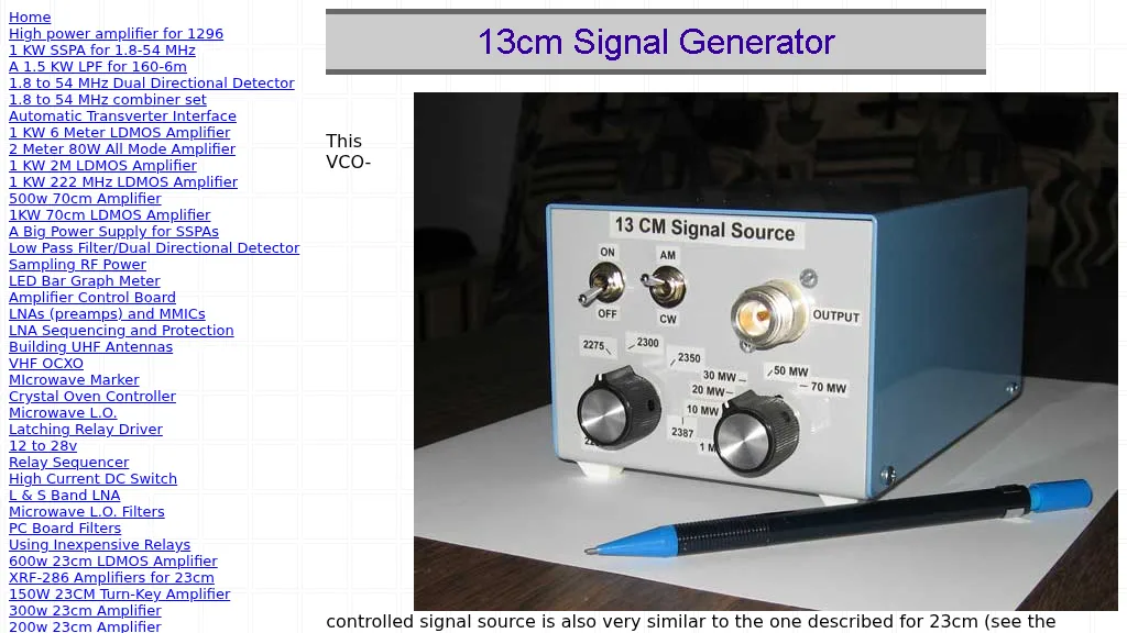 This online construction guide details the assembly of a signal generator specifically for the **13cm band** (2.4 GHz). The curriculum focuses on the integration of a Voltage Controlled Oscillator (VCO), specifically the ROS-2400, to produce a stable RF signal. The resource outlines the necessary components for frequency generation and output, including the use of a Mini-Circuits MMIC amplifier for signal conditioning. The construction protocol involves configuring the ROS-2400 VCO to operate within the 2.3 GHz to 2.45 GHz range, ensuring frequency coverage for amateur radio _microwave experimentation_. The guide specifies the output power level, approximately 70mW, directly from the MMIC stage, indicating its application as a low-power instrumentation source rather than a transmit-capable device. This project provides a practical example of constructing a dedicated test instrument for microwave frequency measurements and system alignment on the **13cm band**. DXZone Focus: Construction Guide | 13cm Signal Generator | VCO Integration | Microwave Experimentation