Search results
Query: led swr meter
Links: 50 | Categories: 0
-
 The HB9ABX mobile HF antenna, developed by _Felix Meyer_, offers a high-performance alternative to commercial mobile antennas for 80 through 10 meters. Constructed from fiberglass rods and enamelled copper wire, this design incorporates a loading coil with multiple taps, allowing for band-specific tuning. The article provides detailed instructions for winding the coil, connecting the antenna elements, and integrating it with a vehicle's chassis ground. Field tests conducted at 100W consistently showed the HB9ABX antenna outperforming a HUSTLER mobile antenna by up to **10 dB** (1 S-point) and a YAESU ATAS-100/120 by **18 dB** (2-4 S-points) across distances from 5 km to 1000 km. The design emphasizes a robust ground connection and the use of an antenna tuner, such as an _MFJ-901B_, for optimal SWR on all bands, particularly 40 and 80 meters. Initial adjustment involves setting whip length and coil tap positions to achieve resonance without a tuner, followed by fine-tuning with the tuner during operation. Specific measurements are provided for checking resonance on 21.0 MHz and 14.2 MHz, with precise turn counts for the lower (79 turns) and upper (120 turns) antenna sections. Safety precautions for handling fiberglass dust are also highlighted.
 -
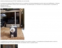 A 1.5-meter telescopic whip antenna project for the Yaesu FT-817 QRP transceiver is presented, offering a cost-effective alternative to commercial portable antennas like the Whip Miracle. The design incorporates a **toroidal matching unit** with a rotary switch for band selection and a toggle switch for fine-tuning the coil taps. This setup allows operators to achieve a low **Standing Wave Ratio (SWR)** across various HF bands, despite the inherent limitations of a physically short radiator on lower frequencies. The construction details include photographs of the completed unit, showcasing the compact enclosure and the integration with the FT-817. A simple schematic illustrates the coil tapping arrangement and the switching mechanism, guiding hams through the assembly process. The project emphasizes practical, portable operation for **QRP** enthusiasts, acknowledging that while performance on bands like 80m or 40m will be modest, it can still facilitate contacts under favorable conditions with skilled operation.
 -
 Constructing a **reduced-size coaxial Moxon rectangle** antenna for the 17-meter band is detailed, presenting a method to achieve a compact directional antenna. The resource outlines the use of RG-58/U coaxial cable for elements, enabling a substantial reduction in physical dimensions compared to traditional wire or tubing Moxon designs. It provides specific instructions for tuning coaxial elements using an **MFJ-259B antenna analyzer**, including a formula to calculate trimming lengths based on measured resonance and desired frequency. The article explains how to prepare the coaxial cable for both driven and reflector elements, specifying connections for testing and final assembly. Performance data from an MFJ-259B shows SWR readings between 1.0 and 1.2 across 18.068 MHz to 18.168 MHz, with R values from 51 to 59 ohms and X values of 0 or 6 ohms. The antenna's power handling is approximately 500 watts continuous, limited by the RG-58/U coax. Comparative receive testing against an All-Band Sterba Curtain at 50 feet indicated a 2 S-unit reduction for the coaxial Moxon at 9 feet, suggesting optimal performance at a height of 34-40 feet for a 15-18 degree take-off angle. The design achieves an electrical quarter wavelength with over 30 percent size reduction.
 -
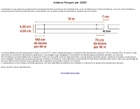 The _Morgain_ antenna for 40/80 meters is a straightforward and cost-effective wire antenna design, requiring careful tuning for optimal performance across two bands with low SWR. Construction involves creating 12 cm PVC spacers with three holes for wire insertion, along with larger terminals for anchoring and connector housing, which should be sealed with silicone. The provided measurements detail the specific lengths for the antenna elements, crucial for achieving resonance on both 40m and 80m bands. Tuning the Morgain antenna necessitates fabricating four wire segments with pins to temporarily connect and adjust the bridging points symmetrically for both 40m and 80m. This iterative process, though time-consuming, ensures the antenna functions effectively for decades once the precise connection points are soldered and protected. The design emphasizes ease of construction and long-term stability, making it a practical solution for hams seeking a dual-band wire antenna.
 -
 Presents a catalog of **QRP** transceivers, antenna tuners, and related accessories for amateur radio operators. The product line includes the ZM-2 antenna tuner, designed for efficient impedance matching across HF bands, and the NW-series QRP transceivers, offering low-power CW operation. Additionally, the site details various ladder line insulators and specialized connectors, emphasizing robust construction for field deployment and home station use. Each product listing provides specifications, operational parameters, and pricing information. Compares the features of different **QRP transceiver** models, such as the NW-40 and NW-20, highlighting their respective band coverage and power output capabilities. The ZM-2 tuner's performance is detailed with typical SWR reduction figures for various antenna types, demonstrating its utility for portable and fixed stations. Customer testimonials and product images illustrate the practical application and build quality of EMTECH's offerings, providing insights into their durability and ease of integration into existing amateur radio setups.
 -
 Presents a crystal-controlled CW transmitter design for the 40-meter band, delivering 5 to 7.5 watts output power. The circuit innovatively employs an _IRF510_ power MOSFET in the final amplifier stage, diverging from conventional bipolar transistors. This design offers high gain, nearly 90% efficiency, and robust resistance to high SWR, allowing 30-second key-down operation into an open circuit without damage. A critical aspect is the precise adjustment of the MOSFET gate bias via a 10K trimmer pot, _R10_, to maintain quiescent current between 5 and 10 mA, preventing thermal runaway inherent to bipolar devices. The prototype was constructed on a _Radio Shack universal board_ and achieved immediate operational success. The design requires a 15-volt Zener diode to protect the MOSFET gate from overvoltage. Component sourcing information is provided, including specific crystal frequencies (7.040 MHz or 7.122 MHz) available from _Dan’s Small Parts & Kits_ or Doug Hendricks. The fixed frequency can be slightly adjusted with a trimmer capacitor. A complete bill of materials, including resistor values, capacitor types, toroid specifications, and transistor part numbers, is detailed, alongside a clear schematic diagram.
 -
 Presents a detailed construction guide for a 2-element _Moxon rectangle_ antenna optimized for the 10-meter band, designed by L. B. Cebik, W4RNL (SK). This resource demonstrates how to build a compact beam antenna using readily available hardware store aluminum tubing, fitting within a 12-13 foot width. It highlights the antenna's performance characteristics, including a gain comparable to a 2-element Yagi (11+ dBi) and a front-to-back ratio exceeding 20 dB between 28.3 and 28.5 MHz, with an SWR below 2:1 across the entire band. The design emphasizes direct 50-ohm coax connection without a separate matching system, though a 1:1 choke _balun_ is recommended. The guide provides practical advice on element construction, corner fabrication using L-stock or radius-bent tubing, and the critical side-to-side length adjustment for SWR optimization. It details the feedpoint assembly using a chassis-mounting coax connector and discusses element-to-boom plate options, including spar varnished plywood or LE plastic. The author's experience with a test model on a 20-foot mast confirms stable feedpoint characteristics and excellent performance even at lower heights. The document also includes insights into the antenna's free-space azimuth patterns, noting a broad forward lobe and significant front-to-back rejection. It contrasts the Moxon with traditional Yagis, positioning it as an effective, home-buildable alternative for compact sites or _Field Day_ operations, particularly beneficial during periods of increased 10-meter activity.
 -
 A 70 MHz Moxon rectangle antenna, built with 0.83mm enamelled copper wire and a lightweight fiberglass kite spar frame, offers a compact two-element beam solution for the 4-meter band. This design, originally for HF, scales effectively to VHF, reducing the antenna's width to approximately 75% of a half-wavelength while allowing direct coaxial cable feeding. The author, G6GVI, details the construction process, including the use of an automated design tool for precise dimensions. Initial field testing revealed a VSWR of approximately 1.3, with distinct nulls observed at 90 degrees when the antenna was mounted horizontally. The lightweight build, supported by a wooden block and U-bolt for mast attachment, makes it suitable for thinner mast sections. Further experimentation included testing with vertical polarization and considering its potential for indoor loft installation due to its relatively short major axis, offering a discreet option for urban hams.
 -
 The "EZ-Tuner" is a homebrew automatic legal-limit antenna tuner that covers all amateur HF bands from 160-10 meters. Using a T-network design and controlled by a BASIC Stamp BS2sx microcontroller, the EZ-Tuner will match at least a 16:1 VSWR for either unbalanced or balanced transmission lines.
 -
 The K5OE 2-meter vertical mobile antenna design, detailed in this resource, employs a 3/8-wavelength vertical section complemented by four shortened radials, forming an off-center-fed vertical dipole. This configuration creates a self-contained lower half, enhancing efficiency compared to traditional 1/4-wave monopoles relying on vehicle bodies for a ground plane. The article specifies construction using PVC components, 10-gauge insulated wire for elements, and provides precise dimensions in both inches and centimeters for the 25-3/16" (64 cm) vertical and 7-3/16" (20 cm) radials. Performance data indicates an honest 3 dBi of gain at 6 feet elevation (2 dBi free-space), with a pattern favoring the horizon, suitable for Low Earth Orbit (LEO) satellite communications. At 20 feet high, the same antenna exhibits almost 6 dBi of gain, with a nominal 50 Ohm feedpoint impedance at 146.850 MHz. Tuning instructions involve trimming element lengths, with the author achieving a 1.2:1 SWR by pruning the mast to 24-3/4" and radials to 7". The resource highlights the antenna's effectiveness for mobile LEO satellite uplinks, particularly at low elevations, and its suitability for fixed, mobile, or portable operations. The flexible wire elements allow for easy folding, making it a practical choice for backpacking. The original design by K5OE was previously hosted on aol.com.
 -
 The resource details the construction and performance of a dual-band 40/30 meter _Moxon_ antenna, evolving from an initial single-band 30-meter design that failed in a storm. It specifies materials such as four 10-meter fishing rods, galvanized iron TV antenna support pipes, 1mm diameter PVC-covered copper wire, and a piece of 75-ohm TV satellite cable for feedline. The document outlines the iterative design process, including initial resonance measurements of 9.9 MHz for 30 meters and subsequent recalculations to shift the center frequency by 300 kHz using _Moxon software_. Initial testing on a roof yielded SWR readings of 1.4:1 at 7.200 MHz and 1.5:1 at 10.280 MHz. After installation atop a 30-meter tower, the final SWR measurements were 1.1 at 7.130 MHz and 1.4 at 10.230 MHz, with a notable 30 dB front-to-back ratio on 40 meters. The 30-meter performance, while good, showed a front-to-back ratio of approximately 15 dB, suggesting a slightly high resonance. The antenna's placement on a 700-meter hill, with a significant ground drop in certain directions, is noted as a potential factor in its excellent DX performance, enabling daily contacts with the USA West Coast on 30 and 40 meters with 100 watts.
 -
 A rotary trapped-dipole for 17 and 20 meters, as described by IZ7ATH, presents a practical solution for multi-band HF operation. The author, Talino, recounts his experience building this antenna for IK7ZCQ, detailing the evolution from an initial concept involving a grounded-driven element and gamma-match to a direct-fed, non-grounded design. His pragmatic approach, adapting available materials, is evident throughout the construction narrative, particularly with the use of eight tapered aluminum pipes for the driven element. Construction specifics include precise measurements for the aluminum tubing, with diameters ranging from 30 mm down to 16 mm, and a critical note on reducing tip thickness for weight optimization. The _traps_, initially a concern, are fabricated using 8 turns of RG58 coax on a 27 mm support, tuned to resonate at 18.1 MHz using a dip-meter. Talino emphasizes sealing the traps with RF glue and PVC tape to prevent water ingress, a crucial step for longevity. Field test results, conducted on a 10-meter pole in a clear garden environment, showed an SWR of 1.2:1 on 17 meters and 1.5:1 at 14.200 MHz. While SWR varied slightly when installed at Mario's QTH due to nearby objects, the antenna's performance remained commendable. The final half-dipole length is 46 cm for the 18 MHz tips, and the total weight is under 6 kg, with potential for further reduction.
 -
 MoxGen is a **Windows** application designed to calculate dimensions and generate antenna model files for 50-ohm **Moxon Rectangle** antennas. Users input the desired design frequency in MHz and the wire size (AWG or diameter in inches/mm), and the software outputs the precise element lengths, spacing, and overall dimensions required for construction. It also creates a .maa file compatible with EZNEC, enabling further analysis and optimization of the antenna's performance characteristics. The software provides a visual representation of the Moxon rectangle, displaying key parameters such as gain, front-to-back ratio, and SWR at the design frequency. This allows radio amateurs to quickly assess the potential performance of their proposed antenna before physical construction. The generated EZNEC model facilitates detailed pattern analysis, impedance matching, and interaction with surrounding structures, proving useful for both initial design and fine-tuning.
 -
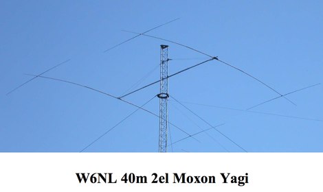 This resource presents a detailed analysis of the W6NL 2-element 40-meter **Moxon Yagi** antenna, covering its design, construction, and measured performance characteristics. It outlines key specifications such as a free-space gain of 6 dBi, 11 dBi at 70 feet, and a direct 50-ohm feed. The document highlights the antenna's physical attributes, including 52-foot elements, a 27-foot boom, and a weight of 75 pounds, engineered to withstand 125 mph winds. Modeling was performed using **AO6** and K6STI software, with a focus on the unique functions of the transverse tip elements for Moxon coupling, physical balance, efficient capacitive loading, and reduced wind load. The presentation includes comparative data, showing the Moxon's superior front-to-back (F/B) ratio and wider bandwidth compared to traditional loaded Yagis. Performance graphs illustrate the SWR, gain, and F/B across the entire 40-meter band (7.0-7.3 MHz), comparing measured results against calculated values. Azimuth and elevation patterns demonstrate high F/B, with the antenna's pattern matching that of a full-size 3-element Yagi on a 30-foot boom. It also notes a gain difference of 1.5 dB down relative to a K3LR 4-element Yagi on a 50-foot boom, providing practical benchmarks for performance evaluation.
 -
 Details the construction of a portable _Moxon_ antenna optimized for the 2-meter band, utilizing readily available materials like 6.5 mm aluminum elements and a 15x15 mm TV boom. The design emphasizes ease of assembly and portability, making it suitable for field operations. Performance specifications derived from MMANA modeling indicate a forward gain of **6.3 dBi** and a front-to-back ratio of **15 dB**. Lateral attenuation is reported at 40 dB, with a minimum SWR of 1.1 at 144.300 MHz, confirming efficient operation within the target frequency segment. The antenna is lightweight at 500 grams, quickly assembled in approximately two hours, and disassembles into a compact 40x15x8 cm package. Direct feeding with RG-58 C/U or KX-15 coaxial cable via a BNC connector simplifies deployment.
 -
 Details a practical QRP wattmeter construction, leveraging a simplified SWR meter design by JA6HIC. The project focuses on a forward-only power measurement circuit, providing a functional instrument for RF power levels from milliwatts up to 5 watts. It maintains a 50-ohm input and output impedance, suitable for typical QRP transceivers and antenna systems. The resource includes the schematic for the "VSW" (Very Simple Wattmeter) and outlines a six-step alignment procedure. This calibration process involves using a known RF source up to 5W, setting full-scale deflection, and marking power increments. It also addresses minimizing frequency effects on readings with a 100pF trimmer capacitor, noting that measurement error is highest at the lower end of the scale. Construction notes mention using a piece of RG-213 coaxial cable for the inductance and coupler, with the wattmeter assembled in early 2003. The author provides an example measurement showing 0.8W into a dummy load and 1W into a 3-element beam.
 -
 Presents the design and construction of an automatically tuned 7-30 MHz mobile HF vertical antenna, originally published in _QEX / Communication Quarterly_ in 2003. The resource details a base-loaded vertical antenna system that mounts on a vehicle's roof, incorporating a variable inductor as its loading coil. A three-legged chariot, driven by a modified model airplane servo, travels inside the coil to adjust inductance. The control unit, featuring a _Basic Stamp microcontroller_ and SWR sensor, emulates a Kenwood AT-50 tuner for seamless integration with a _Kenwood TS-50_ transceiver, allowing automatic tuning across all ham bands from 40 to 10 meters. The project emphasizes practical application, providing a solution to the narrow-banded nature of mobile HF antennas and the inconvenience of manual band changes. It achieves a maximum SWR of 1.3:1 across its operating range. The mechanical design is thoroughly documented with detailed drawings, including a full-resolution GIF and AutoCAD R14 DWG files, illustrating components like the stainless steel whip, PVC coil tube, and the servo-driven chariot mechanism. Construction requires a lathe, but the author notes it can be accomplished with a hobby lathe, making it accessible to those with moderate mechanical skills.
 -
 The N0KHQ Coax Square antenna, designed for 17 meters and built using RG-58 coaxial cable, presents an intriguing option for hams with limited space. L. B. Cebik, _W4RNL_, meticulously models and analyzes this array, clarifying its classification not as a modified Moxon, but as a distinct member of the "dual-coupled, 2-element, parasitic array" family. The design leverages the velocity factor of RG-58 (approximately 0.66-0.67) to achieve significantly shorter element lengths compared to full-size counterparts, resulting in a perimeter of 42 feet for the N0KHQ array versus 54 feet for a standard Moxon. _NEC_ modeling reveals the coax square's performance characteristics, including a forward gain of 5.6 dBi and a 23.7 dB front-to-back ratio on 18.118 MHz. While slightly less gain than a Moxon (6.0 dBi), its pattern exhibits Yagi-like nulls at 90 degrees, distinguishing it from the Moxon's wider beamwidth. The article also delves into the unique feedpoint considerations, explaining how the split braid and center conductor of the RG-58 driver effectively form a folded dipole, allowing for impedance transformation to achieve a good match for 50-Ohm cable. Despite its shortened elements, which inherently narrow the operating bandwidth, the coax square maintains satisfactory performance across the 17-meter band. The analysis emphasizes that while SWR curves are important, a holistic view of gain and pattern degradation across the band is crucial. This antenna is a viable solution for operators needing a compact, directional array, particularly for narrow bands like 17, 30, or 12 meters, where its high-Q performance is most effective.
 -
 This project outlines the construction of a 3-element reversible quad antenna specifically designed for the 40-meter band. The materials required include pushup towers, pressure-treated posts, insulated wire, and various electrical components such as relays and a balun. The construction process is straightforward, beginning with the installation of the posts in a straight line, followed by the assembly of the antenna elements and their elevation to the desired height. The antenna's design allows for directional signal reception, making it ideal for operators looking to enhance their communication capabilities on the 40-meter band. The project includes detailed instructions on tuning the antenna for optimal performance, ensuring that operators can achieve the lowest SWR possible. Additionally, the design can be adapted for other bands by extrapolating dimensions, providing versatility for amateur radio enthusiasts. Overall, this reversible quad antenna project is suitable for both beginners and experienced operators, offering a practical solution for improving signal strength and directionality in 40-meter communications.
 -
 Presents the construction and performance characteristics of a **2-meter vertical Moxon** antenna designed by WB5CXC. The antenna utilizes 1/2-inch PVC and #6 copper ground wire for its physical structure. Performance data includes measured front-to-back ratio using a local repeater, demonstrating significant signal attenuation when rotated. The resource provides **antenna pattern** plots, with blue tracing the design at 146 MHz and red indicating performance at 148 MHz. Gain and SWR plots are also included, alongside a detailed diagram of the antenna's physical layout. The design emphasizes a good front-to-back ratio, aligning with modeling predictions.
 -
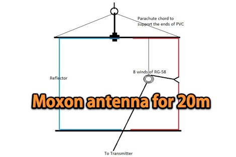 A 20-meter vertical _Moxon_ antenna, designed for portable operation, is detailed with specific dimensions for its driven and reflector elements. The project outlines the construction process, including the use of PVC pipe for the frame and #14 AWG insulated wire for the elements. The antenna's compact size and directional characteristics make it suitable for field day operations or limited space environments, offering a gain of approximately 5.5 dBi and a front-to-back ratio of 20 dB. Testing revealed a 1.2:1 SWR at 14.250 MHz, demonstrating good impedance matching across the target frequency range. The _Moxon rectangle_ design provides a clean radiation pattern with minimal side lobes, which is advantageous for reducing QRM from unwanted directions. This build offers a practical solution for hams seeking a lightweight, easily deployable directional antenna for 20 meters without the complexity of a full-sized Yagi.
 -
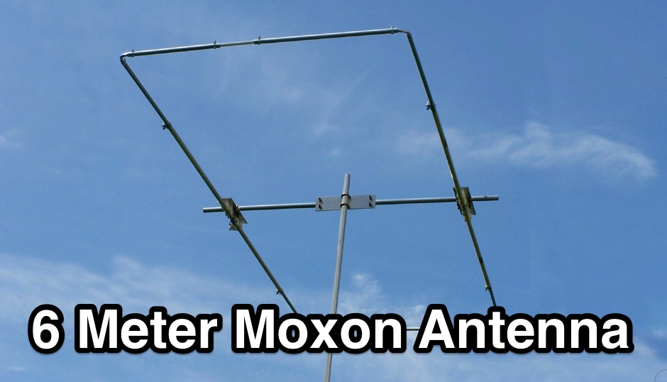 The resource details the construction of a 6-meter _Moxon_ antenna, presenting two distinct versions: one horizontally polarized for 50-51 MHz CW/SSB and another vertically polarized for 52-54 MHz FM. It specifies the use of 5/8 inch OD and 1/2 inch OD aluminum tubing, with 3/8 inch OD solid aluminum for corners, and provides a comprehensive material cutting schedule. The design aims for robust, portable construction, with all materials costing under $100. Detailed drawings and EZNEC models are referenced for precise dimensions and assembly, ensuring accurate element spacing and impedance matching. The EZNEC model for the H-POL version predicts a gain of **11 dBi** and a front-to-back ratio of **25 dB** at 50.5 MHz, while the V-POL version shows a gain of **6.7 dBi** and a front-to-back ratio of **36 dB** at 53 MHz. The article includes practical SWR measurement advice, noting the impact of coax length and loss on analyzer readings. Field tests during a tropical storm demonstrated the antenna's durability and performance, yielding numerous contacts across significant distances, including California, Colorado, and Texas, on SSB and PSK.
 -
 The W4NFR 40-meter mobile vertical antenna project details the construction of a mobile antenna system, drawing inspiration from a July 2011 QST article by VE6AB. The design simplifies the top hat by integrating an 8-spoke top hat from Tar Heel Antenna. The resource outlines the tuning process, which involves adjusting the L1 coil for the desired band segment and then fine-tuning SWR with an L2 coil at the feed point. The author achieved a 1:1 SWR at 7.150 MHz with this configuration. The project includes specific instructions for adding anti-sway supports to ensure stable operation and reduce physical stress on the ball mount during vehicle motion. Visual aids such as drawings of the 40-meter mobile antenna, detailed views of the coil and top hat assembly, and an illustration of the ball and spring mount are provided to guide the builder through the construction and installation phases. The content focuses on practical implementation and tuning for optimal performance on the 40-meter band.
 -
 Optimizing a G5RV or ZS6BKW multiband wire antenna for HF operation often involves addressing common SWR issues and understanding feedline characteristics. This resource chronicles the construction and performance evaluation of a G5RV, initially built for 80m, 40m, 15m, and 10m bands, by a newly licensed Foundation operator. The author details the selection of materials, including 3.5 mm stainless steel wire for the doublet arms and enameled copper wire for the open-wire feeder, and the initial decision to omit a balun based on common online information. The narrative highlights the initial disappointing performance, characterized by high receive noise and poor signal reports on 80 meters, despite the transceiver's internal ATU achieving a 1:1 match. This led to experimentation with a coax current balun and further research into G5RV myths, such as SWR claims and the necessity of a balun. The author then describes modifying the antenna to the ZS6BKW configuration, which involves specific changes to the doublet and feedline lengths, and integrating a 1:1 current balun wound on a ferrite toroid. The modifications resulted in improved reception and transmit performance across the bands.
 -
 A 2-meter Moxon beam antenna, designed for the _144 MHz_ band, is detailed, originating from a desire to participate in the PW 2m QRP contest. The design, based on a Moxon Rectangle, offers a compact directional solution for VHF portable operations. The author, G0KYA, constructed the antenna using readily available materials like 15mm plastic conduit for the frame and 1.5mm copper wire for the elements. Initial testing with an MFJ-259B antenna analyzer showed a **1.2:1 SWR** at 144.300 MHz, indicating good resonance. The antenna's compact size, approximately 70cm x 40cm, makes it highly suitable for portable QRP work, providing a significant advantage over an omnidirectional vertical. The project includes practical advice on element spacing and construction techniques, emphasizing ease of assembly for field deployment. Field results from a local hilltop demonstrated the Moxon's directional characteristics, allowing for effective nulling of local noise and improved signal reception from specific directions.
 -
 A Variable Base-Loading-Coil provides a practical solution for optimizing HF mobile whip performance across multiple bands. The design, as presented by VK4ADC, details a coil wound on a 50mm PVC former, utilizing 1.6mm enamelled copper wire for robust construction. This approach allows for precise tuning, a critical factor in achieving efficient radiation from a mobile setup, where antenna length is often compromised. My own field experience with similar base-loaded whips confirms the importance of a well-designed loading coil for maximizing signal strength and minimizing SWR. The VK4ADC design incorporates a sliding contact, enabling continuous adjustment, which is superior to fixed taps for fine-tuning resonance on the fly. This variable inductance allows the operator to quickly adapt the antenna to different HF segments, from 80 meters up to 10 meters, without needing to swap out multiple coils. The document includes specific winding data, such as the number of turns per inch and the overall length of the coil, which are essential for replication. It also touches upon the mechanical aspects of integrating the coil with a standard mobile whip, ensuring a stable and weather-resistant assembly for reliable operation during mobile DXing or casual rag-chewing.
 -
 Demonstrates the construction and implementation of a **two-element phased vertical array** for 40 meters, utilizing _Christman phasing_ techniques. The author, W4NFR, details the process from building individual 1/4-wave aluminum verticals to integrating them into a phased system. The resource covers antenna spacing of 32 feet, elevated radial design, and the critical steps for tuning each vertical to achieve a 1.1:1 SWR before combining them. It also provides insights into calculating precise coax lengths for feedlines and the phasing delay line, emphasizing the use of an MFJ-269 Antenna Analyzer for verification. The finished system exhibits good front-to-back nulls, with an overall SWR ranging from 1.6:1 to 2.2:1, which is managed by an antenna tuner. The project includes detailed photos of the relay box, showing 12 VDC relays capable of handling 5KV, and the control box in the shack for switching between three different antenna pattern configurations. Static bleed-off chokes are incorporated for protection, and the construction emphasizes robust weatherproofing for outdoor elements.
 -
 The ZS6BKW multi-band antenna, an optimized variant of the classic G5RV, is presented with detailed construction and tuning instructions. This resource outlines the antenna's design principles, which were developed by _Brian Austin (G0GSF)_ using computer programs and Smith charts to achieve optimal dimensions. It provides specific guidance on calculating and adjusting the lengths of the radiators (L1) and the matching ladder line (L2), emphasizing the critical role of velocity factor (VF) in achieving resonance. The article includes a step-by-step procedure for empirically determining the VF of ladder line using an antenna analyzer, ensuring accurate physical lengths for the matching section. It details the tuning process for the radiators, offering practical tips for incremental adjustments to achieve the best SWR curve. The resource presents SWR measurement results obtained with an _AIM-4170C_ analyzer across multiple bands, alongside predicted SWR graphs from an AutoEZ model. It confirms successful contacts on 80, 40, 20, and 17 meters, including a **17-meter DX contact** to Italy. EZNEC and AutoEZ models for the ZS6BKW antenna, covering 80 through 6 meters, are provided for download, allowing further analysis and customization. The document specifies component details, such as the use of Wireman 554 ladder line and #14 AWG THHN copper wire, and discusses the antenna's performance characteristics, noting high SWR on 15 and 30 meters but successful tuning on 6 and 80 meters with an external tuner.
 -
 Constructing a compact, single-feed triband Moxon antenna for 20, 15, and 10 meters is detailed by DU1RZ, drawing from his personal experience with space-constrained antenna projects. Initially fascinated by cubical quads, the author transitioned to Moxon designs in 2005 after realizing his roof space was insufficient for a bulky quad. His first experimental monoband Moxon for 15 meters, built from repurposed materials, provided solid DX QSOs for seven years, despite being slightly below the 21 MHz band center. The project outlines the design process, including using the _MOXGEN Calculator_ for element dimensions and material selection, such as #14 AWG enamel copper wire and fishing poles for spreaders. DU1RZ shares insights from simulations with DL2GMS regarding insulated versus non-insulated wire performance, noting that insulated wire can shift resonant frequencies lower. The assembly instructions cover preparing wire elements, connecting feed points, and tuning the antenna, with initial SWR measurements taken at 10 feet and final readings on a mast showing excellent results: 1.0:1 on 14.225 MHz, 1.1:1 on 21.250 MHz, and 1.3:1 on 28.50 MHz. Transmission tests with 4F1BYN indicated a front-to-back ratio of approximately 2 S units with 10 watts output. The author emphasizes adaptability, encouraging builders to use readily available materials rather than strictly replicating his setup. Key observations from DU1RZ and DL2GMS highlight the antenna's strong performance across 20, 15, and 10 meters, good front-to-back ratio, full bandwidth on 20 and 15 meters, and its small turning radius of about 4.18 meters (13.54 feet), making it suitable for limited antenna space. Its lightweight construction and low wind load are also noted as significant advantages.
 -
 Demonstrates various practical amateur radio projects and technical discussions through video episodes. One episode details cutting and retuning a _1/4 wave shorted stub_ from 101.7 MHz to 107.5 MHz to safeguard a transmitter's driver stage, alongside insights into advanced _160-meter antenna systems_ like eight-circle arrays and beverage antennas. Another segment covers upgrading firmware on an _ATS-20+_ receiver using AverDudes for improved display and functionality, and a detailed guide on using D-Star DR mode on an _ICOM ID-52A_ for international repeater programming. Additional content includes a deep dive into _OpenHamClock_ as a potential replacement for the HamClock project, updates on _Raspberry Pi 5_ running Trixie OS, and a review of the Choyong LC90 Internet radio with AI integration. The series also features "Ham College" episodes, which meticulously prepare viewers for the Technician Exam by covering topics such as antenna and transmission line measurements, SWR interpretation, and the functions of basic electronic components like rectifiers, relays, and transistors. Practical advice on coaxial cable characteristics, dummy loads, and proper soldering techniques is also provided.
 -
 Designing and constructing portable wire antennas for HF operations, this resource explores several configurations including the _foldback dipole_ for space-constrained setups and an inductively shortened dual-band dipole for 20m and 40m. It details the calculation of inductance for shortened elements, providing a Visual Basic 6.0 program screenshot that illustrates determining coil parameters like turns and length for a **25.5 uH** inductor. The document emphasizes practical considerations such as adjusting wire lengths for optimal SWR, noting that a dual-band dipole achieved SWR below 2:1 on both 20m and 40m, with careful adjustment bringing it under 1.5:1. Further, the resource describes a half-wave antenna matched with a coaxial stub, a method often referred to as the _Fuchskreis_ in German amateur radio circles, to transform the high feedpoint impedance to 50 Ohms. This monoband solution, for a 20m application, uses a stub length of **2.98m** (0.216 lambda multiplied by coax velocity factor) and a shorted stub of approximately 48cm. The coaxial stub design is highlighted for its resilience to ground proximity, allowing it to be rolled up or laid on the ground with minimal SWR impact, making it highly suitable for portable QRP operations.
 -
 Presents SWR analysis of an **Alpha-Delta DX-LB Plus** multiband wire antenna, installed as an inverted-V at 40 feet with ends at 15 feet, using an RigExpert AA-54 analyzer. The resource provides a full SWR sweep from 0.1 MHz to 54 MHz, followed by detailed SWR graphs for individual amateur bands including 160m, 80m, 40m, 30m, 20m, 17m, 15m, 12m, 10m, and 6m. The analysis highlights the narrow bandwidth on 80m and 160m due to loading coils, necessitating tuning for specific operating frequencies. It notes excellent SWR performance across the entire 40m band and good results on 10m, also requiring tuning. The author shares personal experience with the antenna, including a 17,000 km QSO on 20 meters, and discusses plans to replace it with a homebrewed parallel **fan-dipole**.
 -
 The NB6Zep Antenna, an electrically shortened 80-meter end-fed wire, addresses space constraints for low-band operation by integrating two loading coils into a 37-foot wire. This design, modeled with _EZNEC_, explores configurations like the quarter-wave sloper and inverted-L, with the latter providing a more vertical radiation pattern and practical backyard deployment. The resource details specific coil construction, recommending 21 uH coils made from _BW coil stock #3026_ or similar, and outlines wire segment lengths for optimal tuning. Performance analysis indicates a radiating efficiency of approximately 27% with good ground conductivity, resulting in a signal typically 3-4 dB down compared to a full-size quarter-wave vertical. The antenna exhibits a narrow bandwidth, around 50 kHz, due to its high Q, necessitating a tuner for broader band operation. Feedpoint impedance is low, with ground resistance playing a critical role in achieving a usable SWR. The article emphasizes the importance of an effective ground rod at the feedpoint for proper operation and tuning, suggesting an antenna analyzer for precise adjustments. It confirms the antenna's suitability for DX, citing successful contacts from Oregon to the East Coast and Hawaii on a 160-meter variant, making it a viable option for urban operators seeking low-angle radiation on 80 meters.
 -
 This resource details the construction of a Moxon rectangle antenna, a two-element wire beam, drawing inspiration from a _QST_ article by Allen Baker, KG4JJH, and a project group led by KD6WD. It outlines the use of _AC6LA_ software for critical measurements (A-E) to design the antenna for specific bands like 17 meters, emphasizing the simplicity of adjusting frequency and wire size. The guide covers material selection for spreaders, such as telescoping fiberglass fishing poles, and various hub constructions, including aluminum tubing and PVC joints, with accompanying images. The author shares practical insights from building multiple Moxons for 10, 15, 17, and 20 meters, noting consistent 1:1 SWR at design frequencies and broadbanded performance. It describes the feedpoint assembly using a 1:1 Yagi current balun and wire nuts for robust, adjustable connections. The resource also discusses element insulators made from Lucite strips and attachment methods to spreaders using plastic wire ties and duct tape, ensuring precise element spacing. Performance observations include significant signal improvements (4-5 S units) over quad loops and a unique "DX-Vane" effect where the suspended antenna self-aligns with the strongest DX signal. The author also recounts an unsuccessful attempt at a dual-band 17/20 meter Moxon, concluding that the Moxon is inherently a monoband antenna, supported by _EZNEC_ plots for a 17-meter design.
 -
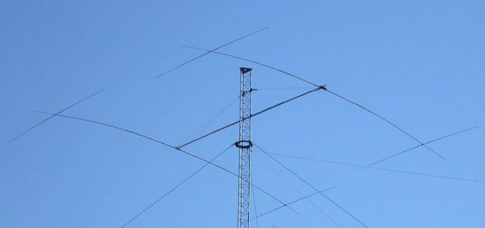 The W6NL Moxon Yagi is a high-efficiency two-element 40m Yagi that uses cross elements to provide both loading and Moxon coupling, addressing the challenge of deploying a directional antenna on the 40-meter band. This resource details the transformation of a _Cushcraft XM240_ Yagi into this Moxon configuration, replacing the original loading coil LCA sections with four new assemblies. The guide provides comprehensive instructions for building the boom and elements, including specific dimensions for new sections and tee loading elements, along with detailed drawings and a full parts list for the conversion. Performance data indicates the converted antenna achieves **10.73 dBi** gain at 7.050 MHz with 99.5% efficiency and a high front-to-back ratio. The VSWR bandwidth is over **300 kHz**, ensuring good performance across a significant portion of the 40m band. Construction involves reinforcing element sections, attaching tee loading elements with U-bolts, and implementing element guying using materials like _Phillystran_ to manage sag and maintain structural integrity.
 -
 The article, "Using 75 Ohm CATV Coaxial Cable," details methods for employing readily available 75-ohm CATV hardline in standard 50-ohm amateur radio setups. It addresses the inherent impedance mismatch and practical considerations, such as connector compatibility, for hams seeking cost-effective, low-loss feedline solutions. The resource specifically contrasts common 50-ohm cables like RG-8, RG213, and _LMR-400_ with 75-ohm hardline, highlighting the latter's lower loss characteristics, particularly at VHF and UHF frequencies. It explores two primary approaches to manage the impedance difference: direct connection with an acceptable SWR compromise and precise impedance transformation. The direct connection method acknowledges that a perfect 1:1 SWR is not always critical, especially when using low-loss coax. For impedance transformation, the article explains the use of half-wavelength sections of coax to reflect the antenna's 50-ohm impedance back to the transmitter, noting its single-frequency effectiveness. It also briefly mentions transformer designs using toroid cores and a technique involving two 1/12 wavelength sections of feedline for broader bandwidth. The content further clarifies the concept of _velocity factor_ for calculating electrical versus physical cable lengths, providing a generic formula for precise length determination. It notes that while half-wave matching is practical for 10 meters and above, it can result in excessively long runs for lower bands like 160 meters, potentially adding **250 feet** of cable. The article also mentions achieving a usable bandwidth of 28.000 MHz up to at least **28.8 MHz** on 10 meters with specific transformation techniques.
 -
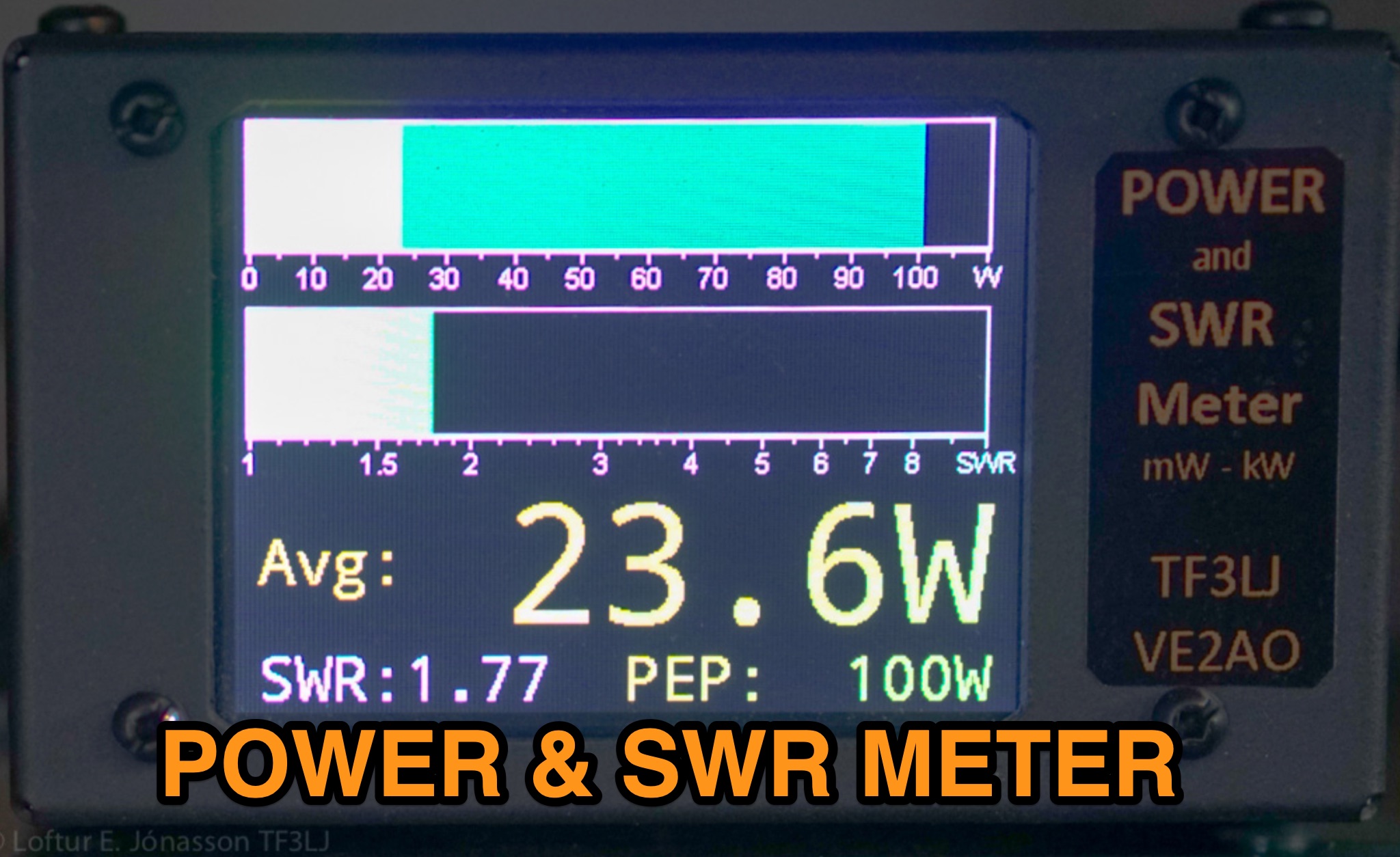 This page describes an update to a project for a Power and SWR Meter for ham radio operators. The update includes a more powerful microcontroller, increased sampling rate, and improved display options. It explains how to use the new components and provides detailed instructions for building the updated meter. The page also offers alternative display options and includes the full source code for the firmware. Overall, this update enhances the functionality and performance of the Power and SWR Meter project, making it more versatile and user-friendly for hams looking to measure RF power and SWR in their radio setups.
 -
 Building an End-Fed Half-Wave (EFHW) antenna from a kit, as detailed by Frank Bontenbal, PA2DKW, with process photos by Bob Inderbitzen, NQ1R, offers a practical approach for hams. This specific kit, a collaboration between ARRL and HF Kits, targets 10, 15, 20, and 40 meters, making it a versatile option for HF operations. Unlike a center-fed dipole, the EFHW is a half-wavelength antenna fed at one end, which simplifies deployment, particularly for portable use. The construction guide meticulously outlines the assembly of the 49:1 impedance matching network, crucial for transforming the antenna's high impedance (around 2,500 Ohms) to a transceiver-friendly 50 Ohms. Steps include preparing the enclosure by drilling holes for the coaxial connector and antenna connections, followed by the precise winding of enameled copper wire onto a toroid to create the transformer. The guide emphasizes careful insulation removal and soldering for reliable connections. Final assembly involves integrating a 100 pF capacitor for higher band compensation, soldering the transformer's primary and secondary sides, and conducting SWR tests with a 2K7 resistor or a half-wavelength wire. The document also provides examples of wire lengths for different bands, such as 16 feet for 10 meters or 66 feet for 40 meters, demonstrating the transformer's adaptability for various half-wavelength configurations.
 -
 Paul McMahon presents a compact VSWR meter designed for QRP portable use, ideal for SOTA operations with rigs like the FT817. The device, constructed from readily available components, employs a simple resistive bridge for wideband performance from 1.8MHz to 52MHz, with diminishing accuracy at higher frequencies. Key features include no need for external power, simple calibration, and operation with low power levels. The design, detailed with parts lists, schematics, and construction guidelines, ensures a 2:1 worst-case VSWR to protect transceivers during antenna matching. Calibration points are set for accurate VSWR readings at various loads.
 -
 Presents a detailed construction guide for a 9 dB, 70cm collinear antenna, utilizing readily available _RG58/U_ coaxial cable and PVC pipe for housing. The resource outlines the critical calculations for ½ wavelength sections at 444 MHz, incorporating the coaxial cable's velocity factor of 0.66, which yields a section length of 223 millimeters. It specifies the preparation and soldering of eight such half-wavelength sections, each cut to 231mm to allow for trimming, forming the core of the array. Further instructions detail the integration of a ¼ wave element (169mm #16 solid wire) at the top and a ¼ wave aluminum tube (160mm, 5/16 inch) at the bottom, crimped to the feed point's braid. The guide also addresses RF common mode current suppression by suggesting the use of _FT50-43_ toroids on the feedline. Final assembly steps cover mounting the antenna within ¾" PVC pipe using a wooden dowel, waterproofing connections, and initial SWR checks. The article also discusses scaling the design for different element counts and other VHF/UHF bands.
 -
 The Portable EFHW antenna for the 40, 20, 15, and 10-meter bands utilizes a broadband transformer with a 1:49 ratio, designed on a PCB by either Jan or DL2MAN. The design incorporates an **FT114 core**, offering an alternative to the FT82 core. The antenna requires precisely 20.5 meters of DX Wire Ultralight for optimal performance. Additional components include DX Wires "Dyneema" 1mm rope and 1mm bricklayers string for structural support. The SWR plot indicates performance at two elevation heights: 5.5 meters (blue line) and 4 meters (yellow line), demonstrating optimization for low-elevation portable use without poles. The antenna's components, including spool and rope tensioners, are available for 3D printing, with spool dimensions scaled to 130% for a length of approximately 110mm. The design emphasizes simplicity and portability, suitable for field deployment.
 -
 The document provides a detailed modification guide for the Zetagi HP201 SWR Wattmeter, converting it for HF amateur band usage. It replaces the original circuit with a Tandem Coupler based on the Sontheimer and Frederick directional coupler patent, enhancing accuracy and sensitivity. Key components include Murata toroid cores, scaling resistors, and a new calibration process. Challenges and solutions during the modification process are discussed, ensuring linear results across 160-10m bands. This guide also includes calibration instructions and theoretical insights into the coupler's operation.
 -
 Effective suppression of harmonics and parasitic radiation from HF transmitters is crucial, especially with the increasing sensitivity of VHF/UHF radio channels to interference. This project details a hybrid low-pass filter (LPF) designed to operate across the HF bands up to 51 MHz, making it suitable for 6-meter band operations while providing deep VHF/UHF suppression. The design addresses the challenge of modern interference landscapes, where even microvolt-level signals can disrupt wireless sensors and other simple VHF/UHF receivers. The filter utilizes a single elliptic link, combining high cutoff steepness with robust suppression in the hundreds of megahertz range. A key feature is the use of only two standard capacitor values, simplifying construction and component sourcing. The article provides a detailed schematic, performance characteristics, and _RFSim99_ model file, demonstrating a reflection coefficient S11 below 0.017 (VSWR < 1.03) across 1-51 MHz, ensuring minimal degradation to the antenna system. Construction notes include coil winding specifications and capacitor selection guidance, with recommendations for _FR-4_ assembly. Two capacitor sets are presented, with the first variant recommended for its lower RF current demands, keeping currents below 3 A at 1 kW passing power at 51 MHz. Fine-tuning involves adjusting frameless coils, with considerations for capacitor tolerance and high-frequency capacitance measurement accuracy.
 -
 Fifty-one MHz operation, often called the "magic band," benefits significantly from a well-designed antenna, and this resource details the construction of a rigid 6-meter _Moxon antenna_ using common DIY store materials. The author, 4L/G8BAG, shares his experience with the 6m band, highlighting its potential for long-distance contacts, with single-hop sporadic E propagation enabling QSOs up to **2,500 km** and multi-hop contacts reaching **10,000 km**. The project emphasizes cost-effectiveness and durability, utilizing yellow gas pipe with an internal stainless steel lining for the antenna elements. The article provides specific dimensions for the Moxon rectangle, derived from the 12mm internal diameter of the gas pipe's steel core, rather than the outer plastic. It also details the use of white PVC water pipe for insulators and mounting, ensuring a tight fit with the yellow gas pipe. Initial testing with an MFJ antenna analyzer showed an excellent 1:1 SWR across the 50-52 MHz range, even when using 75 Ohm satellite cable as a feeder. The construction process is straightforward, involving cutting and bending the gas pipe, fitting insulators, and connecting the feedline. The author's successful on-air results, including a 1000 km contact with a temporary vertical, underscore the effectiveness of the 6m band and the Moxon design. The resource concludes with a note on exploring heavier gauge gas pipe for future 10m antenna projects.
 -
 This project presents a compact QRP SWR meter featuring a 0.96" OLED display (128x64 pixels) for high-contrast visibility, updated with software fixes for display compatibility, improved low-power performance, and support for ATtiny45/85 microprocessors. A 1.3" OLED version accommodates visibility needs. Designed for HF QRP transmitters (3-15W), it uses a Breune coupler with germanium diodes for accurate SWR measurement. Powered by a AAA battery, the meter offers a standalone solution for impedance matching, with a 3D-printed enclosure enhancing portability.
 -
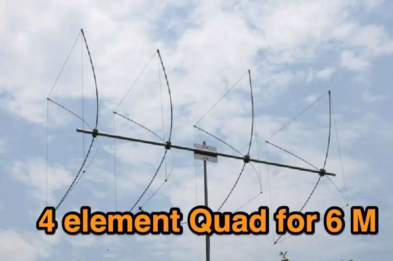 Details the construction of a portable 6-meter 4-element quad antenna, specifically designed for VHF and Field Day operations. The design emphasizes portability and rapid field assembly, utilizing a 10-foot boom, #12 bare wire elements, and fiberglass electric fence post spreaders. It presents specific dimensions for reflector, driven element, and directors, including spreader lengths, circumferences, and corner marks, all derived from a G0KSC design and modeled in EZNEC. The resource outlines the fabrication of synthetic lumber hubs that allow post-assembly adjustments along the boom, and describes spreader clamps made from ¾” OD fiberglass rod, drilled and tapped for 8-32 nylon thumbscrews to secure element wires. It provides instructions for reducing spreader ends to 0.370” OD for proper fit and details the assembly of the boom from two 1½” OD x 6’ aluminum tubes. Performance data from EZNEC modeling indicates a gain of 10.25 dBi (8.1 dBd) and a 20 dB F/B ratio at 50.150 MHz, with SWR values of 1.08, 1.09, and 1.11 at 50, 50.15, and 50.5 MHz respectively. The document includes a field test report from Field Day 2010, where the antenna was deployed at 21 feet, showing an SWR resonance 200 KHz below EZNEC predictions. It notes successful 5-watt QSOs into New York and Canada from Tennessee, highlighting the antenna's excellent directivity and gain compared to a 4 dBd Moxon. The antenna breaks down into easily transportable components, including two 5’ boom sections, a 3’ boom connector, 16 spreaders, and four element/spreader clamp assemblies.
 -
 This report details a modification of a Diamond V2000 antenna, replacing its original two 0.50 m radials with two 1.55 m radials. Initial M5-threaded rods failed to fit; the housing required M6 threads. Custom radials were made using 8 mm OD aluminium tubing and M6-threaded stainless steel ends, secured with nuts machined to 9 mm. SWR issues on 6 m (>2:1) were largely due to a poor counterpoise connection, resolved during reassembly. NanoVNA measurements showed no adverse effects on 2 m or 70 cm. The final setup retains the two 1.55 m radials and original counterpoise. Other operators reported SWR degradation with similar mods—sometimes fixed by adding capacitance—but this was not observed here.
 -
 An Arduino-based interface provides a remote tuner call command for Icom **IC7700** and **IC7800** transceivers, addressing the lack of a built-in function for external tuners such as the MFJ 998RT. This setup initiates a low-power transmit signal, typically 15 watts, allowing the remote autotuner to perform its matching sequence. The article details the required CI-V line communication and modifications to existing Arduino code, specifically referencing contributions from Jean-Jacques ON7EQ for improved Icom interrogation routines. The system involves a sequence of steps: storing the transceiver's current mode and power, disabling the internal autotuner, activating a control relay to interrupt the amplifier line, switching to RTTY mode at low power, and initiating transmit. The transmit duration is manually controlled by the operator, observing the SWR meter until a low SWR is achieved, then a second button press stops the transmission. A built-in 4-second transmit limit provides a safety measure. After tuning, the routine restores the original mode and power settings, re-enables the internal autotuner, and performs a brief 2-second RTTY transmission for internal tuner adjustment. The circuit diagram includes a Panasonic form 2 relay for amp control and emphasizes critical delays in the Arduino code for stable operation at 9600 baud CI-V communication. Compatibility with logging software like DXLab, N1MM, and N3FJP is noted, with specific interrogation time settings required to avoid conflicts.
 -
 Demonstrates various technical projects and tutorials for amateur radio operators, focusing on digital modes, monitoring, and station setup. It covers topics such as implementing a _WSPR_ station, setting up ADS-B reception, configuring a _DXSpider_ cluster, and utilizing monitoring tools like Prometheus and Grafana. The resource provides practical guides for integrating modern IT solutions with ham radio activities, including Docker and Linux environments for radio applications. This site also features a publicly accessible online logbook, offering detailed statistics on QSOs by band, mode, and geographical zone, with visual mapping of contacts. It includes a comprehensive amateur radio lexicon, explaining hundreds of terms, and provides a real-time display of the F4HXN station's local weather conditions. The resource also aggregates information on upcoming ham radio events and offers a **SWR simulator** for antenna analysis, allowing users to visualize ROS changes based on frequency and antenna parameters.
 -
 The 4m Slim Jim antenna project provides a construction guide for a low-cost, high-performance aerial designed specifically for the 70 MHz FM band. This design achieves a 1:1 SWR across the 4m FM band with straightforward adjustment of the feed point, utilizing RG-58 coax. Its low angle of radiation contributes to effective signal propagation. Construction involves using plastic knitting needles as spreaders and a telescopic fishing pole for support, with components secured using two-part epoxy. Annealed bare single-core copper wire forms the radiating element. The setup process includes raising the antenna at least 3 meters above ground for tuning, adjusting the RG-58 feed point for optimal SWR, and then soldering connections. Waterproofing is achieved with yacht varnish. The design emphasizes low wind resistance for durability, making it suitable for exposed outdoor installations. A PDF construction diagram is available to supplement the written instructions.