Search results
Query: 40 80 m antenna
Links: 173 | Categories: 3
-
 This simple antenna is capable of remarkable results on 160, 80 and 40 metres. Forming a triangle from around 50 feet of satellite TV coaxial cable, the top of the triangle can be as low as 15 feet, and the lower side just high enough to prevent a passer by hanging themselves
 -
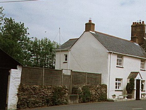
 G8ODE antenna project, where the 40m & Short 80m antenna was deployed as a sloping wire antenna using the 10M fibre glass fishing pole and a hook on the house's gutter-board
 -
 The 6 Band Inverted L Antenna MK3 is a versatile multiband antenna designed for amateur radio operators. This antenna covers 160m, 80m, 40m, 20m, 15m, and 10m bands, making it suitable for a wide range of HF communications. The design is based on a W3DZZ configuration, incorporating traps for optimal performance. The MK3 version features a sturdy 5/8th CB mast, replacing the original timber mast, which enhances durability against harsh weather conditions. The antenna's construction allows for effective operation, particularly on the 40m band, where it has been successfully used to contact distant locations including ZL, VK, and Antarctica. Constructing this antenna requires careful attention to detail, especially regarding the radials and grounding. The traps resonate at specific frequencies, and additional resources are available for building coaxial traps. The antenna is designed to work efficiently without an ATU on the lower bands, while higher bands may require tuning. This project is ideal for both beginner and intermediate operators looking to enhance their station with a reliable multiband antenna.
 -
 Described is a simple inverted-V antenna which, when used with a balanced ATU, can be used on all the main Radio Amateur HF bands (80, 40, 20, 15 and 10m). The cental support is made in such a way that the wire can be coiled up for storage when the antenna is taken down.
 -
 The Chameleon V1 HF Multiband Antenna is a mobile antenna that can also be used as portable. Lightweight mil whip antenna system with 10 BANDS capability 6m, 10m, 12m, 15m, 17m, 20m, 30m, 40m, 60m & 80m.
 -
 Article on the HF dual band antenna with construction details and how to add 160 meters to the HF2V
 -
 A 40 ft vertical dipole antenna that can cover HF Bands from 80 to 10 meters winding a dipole in a 12m HD telescoping fiberglass pole
 -
 Homebrew a vertical antenna for 40 and 80 meters band based on popular HF2V model by DL7JV
 -
 A vertical antenna for 40 and 80 meters band with no need of antenna tuner, based on a telescopic fiberglass mast of 48 feet by N8NSN
 -
 JJ0DRC's HF multi-band delta loop antenna project, initially conceived during the waning peak of Cycle 23, addresses the common challenge of achieving effective DX operation from a small residential lot in Japan. Dissatisfied with a ground plane antenna's performance in SSB pile-ups, the author sought a beam-like solution without a tower, drawing inspiration from a JJ1VKL article in CQ Ham Radio Sep. 2000. The antenna, constructed in October 2000, employs two 7.2-meter fishing rods (37% carbon fiber, reinforced with cyano-acrylate glue and aluminum tape) and 1mm enameled wire, fed by an Icom AH-4 external antenna tuner. While the exact beam pattern remains unmeasured, JJ0DRC observed a significantly higher callback rate compared to dipole antennas, particularly on higher bands. The system's circumference length of 15-20m is crucial for maintaining a good beam pattern across HF bands, though performance on lower bands like 80m, 40m, and 30m becomes less directional as the length deviates from a full wavelength. Ongoing maintenance addressed degradation issues, including aluminum tape cracking and wire breakage at connection points due to strong winds (often exceeding 10-15m/s in winter). The author reinforced rod connections with IRECTOR PIPE SYSTEM components and INSU-ROCK ties, and improved wire attachment methods using Cremona rope and epoxy bond to enhance durability.
 -
 A multiband antenna that can work from 80 to 10 meters in this illustrated docuemnt by G8ODE
 -
 3 Band vertical Marconi-antenna for the bands 40, 80, 160 meters with a ground net of wires as radials.
 -
 A 40 80 dipole antenna design by WA6ESC PDF File
 -
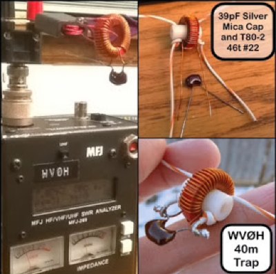
 This article explores a theoretical model for the losses of an 80m / 40m trapped inverted V dipole antenna system using a bootstrap coax trap, but does not examine the pattern of the antenna.
 -
 An inverted V antenna for 40-80 with loading coils. This antenna is a full size on 40 and a shortened 80 by KG0ZZ.
 -
 YF1AR 80 to 40 meter vertical antenna project
 -
 A three-frequency multi-band dipole that can be extended easily to additional bands. This article includes a multiband fan-dipole antenna for 80-40-20-10 meter band.
 -
 This is a popular antenna design as the performance is very good across the HF bands and requires little or no tuning. It is a dipole fed off center with a 4:1 current balun at the offset feedpoint. The antenna shown covers 80, 40, 20 and 10 meters with 15 meters and WARC bands
 -
 An home made trapped dipole antenna for 40 and 60 meters band by 2E0HTS
 -
 An 87ft inverted L portable antenna working on 80 40 30 20 15 meters band
 -
 Operating a ZS6BKW antenna often involves understanding its lineage from the _G5RV_ design, with specific modifications by ZS6BKW to optimize performance on several bands. Through computational analysis and field measurements, the antenna's dimensions were refined to allow operation on 10, 12, 17, 20, and 40 meters without an antenna tuner. For 80, 30, and 15 meters, a tuner is necessary, though efficiency on 30 and 15 meters is noted as not particularly high. The physical configuration consists of two 13.755-meter radiating elements fed by a 12.20-meter section of 450-ohm ladder line. Tuning the antenna on the 20-meter band is critical, and any deviation in the ladder line's characteristic impedance necessitates recalculating the element lengths. The design is also referenced in the 12th edition of _Rothammel's Antennenbuch_, page 219. Proper common mode current suppression is crucial at the transition from ladder line to coaxial cable. This can be achieved with a common mode choke, such as several turns of coax wound into a coil or over a ferrite toroid like an Amidon T130. While a 1:1 balun is an option, it may introduce issues.
 -
 A 90-foot vertical antenna constructed from **aluminum irrigation tubing** is detailed, focusing on its innovative raising and lowering mechanism. The resource describes a **45-foot ginpole** system, allowing a single operator to erect or lower the antenna in minutes. It covers the mechanical design, including the pivot base, insulated joints for the tubing sections, and guy wire attachment points. The antenna consists of two 30-foot sections of 4-inch tubing and one 30-foot section of 2-inch tubing, stacked with the smaller diameter at the top. The electrical design incorporates PVC "condulet" boxes at the 30-foot and 60-foot points, housing relays to change the effective height for multi-band operation on 160, 80, 40, and 30 meters. Ferrite rod inductive chokes are used for DC control and to tune out gap capacitance. The antenna is fed with 1000 feet of open wire line, connected to a matching transformer comprising stacked toroids and a coaxial/toroidal balun. Grounding is achieved with a 3x3 foot grid of 16-gauge tinned copper wires with soldered crossovers.
 -
 An 85ft wire fed against a 17ft counterpoise that works well in 80 and 40 meters
 -
 One specific challenge in the KazShack, operating Single Operator Two Radios (SO2R), involved sharing a K9AY receive antenna between two transceivers without direct RF connection or manual feedline swapping. The solution, detailed in this project, adapts the **W3LPL RX bandpass filter** design to split 160m and 80m signals, feeding them to separate radio inputs while maintaining isolation. This approach also addresses the issue of strong broadcast band interference from a nearby 50KW WPTF transmitter on 680kc. The construction utilizes T-50-3 toroids and NP0 ceramic capacitors, built in a "dead bug" style on copper clad board. Each band's filter coils are identical and resonated to the desired frequency using an MFJ-259 antenna analyzer. A single DPDT relay, controlled by a remote toggle switch mounted on an aluminum panel, facilitates quick band switching between radios, simplifying low-band operations. While some signal loss is noted, the expected lower noise levels from the receive antenna are anticipated to compensate, potentially reducing the need for constant volume adjustments during toggling between transmit and receive antennas.
 -
 A simple 7 bands off-center dipole wire antenna designed to work on 80 meters band and that can cover also 40m 30m 20m 15m 12m 10m with acceptable SWR
 -

-
 How to homebrew a ENVIS antenna for 80 and 40 meters band
 -
 The ZS6BKW antenna, a popular multiband wire antenna, offers improved band matching compared to the traditional G5RV. This construction guide details the process, beginning with specific dimensions: 13.11 meters (43 feet) for the 450-ohm ladder line and initial dipole arm lengths of approximately 14.8 meters each. It emphasizes the critical role of an _antenna analyzer_ for accurate tuning, particularly for determining the velocity factor of the ladder line and achieving a 1:1 impedance match. The article outlines the materials required, including a 1:1 current balun, 450-ohm window line, wire for the dipole arms, and a 50-ohm non-inductive resistor for testing. It provides a step-by-step procedure for cutting the ladder line to its electrical half-wavelength, explaining how to calculate the velocity factor using measured and free-space frequencies. For instance, a measured 50-ohm impedance at 12.54 MHz with a calculated free-space half-wavelength frequency of 11.44 MHz yields a velocity factor of 0.91. Final adjustments involve hoisting the antenna to its operational height and fine-tuning the dipole arm lengths to achieve optimal SWR, specifically targeting 14.200 MHz. The _ZS6BKW_ design is noted for its performance on 80m, 40m, 20m, 10m, and 6m, though it is not optimized for 15m operation. The author, _VK4MDX_, shares practical tips for durable construction using stainless steel wire and cable clamps.
 -
 The Vee Beam antenna project presents a versatile solution for hams, enabling operation across all eight High Frequency bands (80m to 10m) with significant gain on 20m to 10m. This easy-to-construct antenna utilizes two long wires at an angle, enhancing directional performance and minimizing ground losses. With a low visual profile, it is discreet and effective for various applications. The design allows for optimal leg lengths and included angles, ensuring robust performance while maintaining simplicity in construction and operation. The V Beam antenna is an aerial that you can use on all eight High Frequency amateur bands (80, 40, 30, 20, 17, 15, 12 and 10m) with an antenna tuner, and which gives significant gain on the five bands from 20 to 10 meters band.
 -
 Design plan of an array of a two element yagis for 80m and a 3 element 40m antenna sharing a single 12 meters long boom by EA5DY
 -
 Calculate EH Antenna, 20m 40 80m. Fotos, Original eh antenna building.
 -
 A lightweight inverted vee antenna that can be supported by a 10 metre long fiberglass squid pole. The antenna is designed to cover 10, 15, 20, 40 and 80 m bands.
 -
 A schematic antenna for a 40-80 Morgain dipole antenna with diagram and pictures, article partially in german
 -
 An Off-center-feed antenna that covers 80, 40, 20, 17, 15, 12, 10, and 6 meters
 -
 An attic antenna for 40 and 80 meters band by NS1W
 -
 A trapped dipole antenna based on the orignal W3DZZ antenna design resonating on 80 40 20 15 10 meters
 -
 A 50-ohm 10W resistor forms the core of this portable QRP antenna, designed by _K0EMT_ for convenient operation on 160m and 80m. The construction involves soldering the resistor to a BNC connector, with one lead to ground and the other to the center conductor, then insulating the assembly. This minimalist design aims to provide a highly portable solution for low-band QRP operations, acknowledging the inherent trade-offs between antenna size and efficiency. Testing with an antenna analyzer revealed low SWR on both 160m and 80m, with a Yaesu FT-817 confirming good matching. While 40m and 30m showed higher SWR, the primary focus remains on the lower bands. The author successfully tested the antenna with **2.5W CW** output, demonstrating its practical application for QRP field operations where ease of deployment is paramount, even if it means sacrificing some **gain** compared to full-sized antennas.
 -
 An homemade portable trapped dipole antenna for 40 and 80 meters band with an optional extension for the 20 meters.
 -
 This article describes a simple Inverted L antenna for the HF bands designed to work on 80m, 40m, 30m and 20m
 -
 Extension to an existing fan dipole originally modeled for 40 20 and 6 meters. This modification will add 80 15 and 10 meter bands.
 -
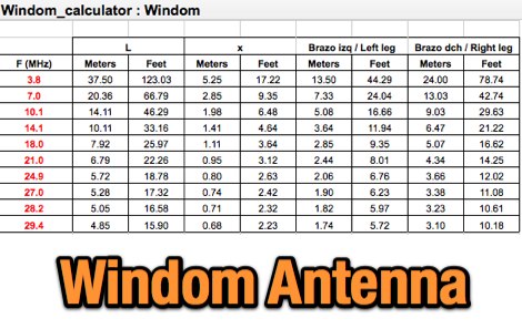 This article describes the characteristics of the Windom antenna and shows the results of several simulations made with MMANA-GAL, covering models optimized for the 20 m, 40 m and 80 m bands.
 -
-
 Optimizing a G5RV or ZS6BKW multiband wire antenna for HF operation often involves addressing common SWR issues and understanding feedline characteristics. This resource chronicles the construction and performance evaluation of a G5RV, initially built for 80m, 40m, 15m, and 10m bands, by a newly licensed Foundation operator. The author details the selection of materials, including 3.5 mm stainless steel wire for the doublet arms and enameled copper wire for the open-wire feeder, and the initial decision to omit a balun based on common online information. The narrative highlights the initial disappointing performance, characterized by high receive noise and poor signal reports on 80 meters, despite the transceiver's internal ATU achieving a 1:1 match. This led to experimentation with a coax current balun and further research into G5RV myths, such as SWR claims and the necessity of a balun. The author then describes modifying the antenna to the ZS6BKW configuration, which involves specific changes to the doublet and feedline lengths, and integrating a 1:1 current balun wound on a ferrite toroid. The modifications resulted in improved reception and transmit performance across the bands.
 -
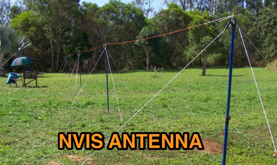
 Deploying robust antenna infrastructure for both fixed and portable operations often requires specialized support structures capable of withstanding environmental stresses while providing optimal radiating element placement. SMC offers a range of solutions, including pneumatic masts and push-up masts, designed to facilitate rapid deployment and reliable long-term support for various antenna types. Their product line encompasses antenna mounts, poles, and complete antenna systems, addressing the critical need for stable and efficient RF communication. The company's offerings extend to HF antennas, including dipoles and _NVIS_ (Near Vertical Incidence Skywave) antennas, which are crucial for short-range regional communications on bands like 80m and 40m. These systems are engineered for durability and performance, ensuring signal integrity across diverse operating conditions. With over **65 years** of experience, SMC has established itself as a global manufacturer in this niche. Their product portfolio also includes antenna support towers, catering to more permanent installations requiring significant height and load capacity for multiple arrays.
 -
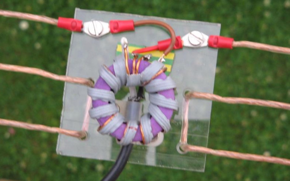
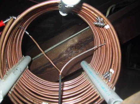
 One point eight MHz to 30 MHz is the operational bandwidth for this 4:1 Ruthroff voltage balun, designed to interface an unbalanced T-Match network with a balanced antenna system. The project details the construction using a _T200-2_ powdered iron toroid core, tightly wrapped in PVC electrical tape for insulation, and wound with 17 double bifilar turns of 1.25mm enamelled copper wire. This outboard balun offers flexibility, allowing hams to trial various baluns based on antenna system and impedance characteristics, rather than integrating it directly into the tuner. The resource includes a schematic of the balun, a wiring diagram showing winding connections, and a table suggesting alternative toroid cores like the T80-2 or T400-2 with corresponding winding counts. Component sourcing is straightforward, listing items such as the _Amidon_ T-200-2 core, SO-239 connector, and a sealed polycarbonate enclosure from Jaycar. Performance evaluation was conducted using an _AIM 4170C_ antenna analyser, demonstrating efficient 1:4 voltage transformation across the specified HF spectrum. Further efficiency tests involved measuring RF power loss at various frequencies, revealing minimal loss—less than 0.7 dB from 3.6 MHz to 30 MHz, and only 2.0 dB at 1.8 MHz. These measurements, performed under ideal 50-ohm conditions, confirm the balun's effectiveness as a low-loss interface for multi-band antenna systems. The page also links to several other balun and unun projects, including 1:1 current and voltage baluns, and 9:1 voltage ununs, providing a broader context for impedance matching solutions.
 -
 The ZS6BKW multiband antenna, an optimized variant of the classic G5RV, features a 102-foot (31.1 m) horizontal span and a 39.1-foot ladder line matching section. This design, derived by G0GSF (formerly ZS6BKW) in the early 1980s using computer programs and _Smith charts_, aims for improved SWR across multiple HF bands compared to its predecessor. Construction details specify Wireman 554 ladder line and #14 AWG THHN copper wire for the radiators, with precise instructions for determining the velocity factor (VF) of the ladder line using an antenna analyzer or dip meter, ensuring accurate physical length for the matching section. The radiator length is electrically 1.35 wavelengths for the 20-meter band, requiring careful trimming during tuning. Field measurements with an _AIM-4170C_ analyzer by KI4PMI and NC4FB demonstrated good SWR curves and bandwidth on 6, 10, 12, 17, 20, and 40 meters. The antenna was deemed unusable on 15 and 30 meters due to very high SWR, but an LDG AT-100PRO autotuner successfully brought 6 and 80 meters into tune. Contacts were made on 80, 40, 20, and 17 meters, including a **17-meter** contact to Spain. EZNEC models for 80-6 meters are provided, along with an AutoEZ model by AC6LA, which predicted good SWR for 80-10 meters. W5DXP's modifications for an all-band HF ZS6BKW are also referenced.
 -
 Operating an 80/40/20M fan dipole for DX is analyzed through EZNEC modeling, focusing on the antenna's performance in a real-world, low-height installation. The resource details the physical construction and SWR measurements of the fan dipole, comparing them against EZNEC simulations. It also incorporates High Frequency Terrain Analysis (HFTA) data to illustrate typical DX elevation angles for various regions from New England, providing a crucial context for evaluating antenna patterns. The analysis presents EZNEC-generated azimuth and elevation patterns for each band (80M, 40M, 20M) at specific frequencies, showing gain figures at different elevation angles relevant to DX propagation. It compares the modeled SWR with measured SWR, attributing discrepancies to coax attenuation. The study concludes with observations on the antenna's azimuth performance (omnidirectional within ±1.5 dB) and its less optimal elevation gain at desired DX angles, highlighting the impact of low antenna height on DX capabilities.
 -
 This project details the construction of a **full-sized 40-meter vertical antenna**, born from a renewed interest in 7 MHz operation and a desire for improved effectiveness over simple dipoles. The author, K5DKZ, initially focused on VHF experimentation, which provided an inventory of aluminum tubing and fiberglass spreaders for this endeavor. Before this vertical, K5DKZ utilized an 80/40 meter inverted-vee trap dipole and a 40-meter broadband dipole, but now primarily uses a pair of full-sized, phased, quarter-wave verticals spaced 35 feet apart for serious 40-meter work. The construction involves a base-heavy design for stability, using a 44.5-inch section of 1-1/4 inch steel TV mast driven into 1-3/8 inch aluminum tubing, insulated by a 105-inch section of Schedule 40 PVC pipe. The assembly reaches 31 feet, close to the 32 feet required for a quarter-wavelength on 40 meters, with fine-tuning achieved by winding wire onto a fiberglass spreader. The design is explicitly presented as a foundation for a two-element 40-meter Yagi beam, outlining modifications like substituting aluminum for steel in the base and using an inductive hairpin match for the driven element. The article also discusses tuning considerations for a large 40-meter beam, noting the 100 to 200 kHz upward frequency shift when raised, and suggesting methods for installation on a tower. The author emphasizes the cost-effectiveness and good performance of the monopole approach, especially when multiple verticals are needed.
 -
 Here is a review of the 40 and 80 meter band Double Bazooka antennas as used on the HF shortwave bands.
 -
 The X80 multi-band HF vertical antenna, a commercial iteration of the Rybakov design, exhibits a physical length of 5.5 meters, or approximately 18 feet, and is constructed from aluminum tubing. It operates as a non-resonant vertical, requiring an external antenna tuner for impedance matching across its intended operating frequencies. The antenna's design incorporates a 1:4 UNUN at its base, facilitating a nominal 50-ohm feed point impedance for the coaxial cable. Performance observations indicate effective operation on 40 meters, 20 meters, 15 meters, and 10 meters, with reduced efficiency on 80 meters and 160 meters due to its relatively short electrical length for these lower bands. Comparative analysis with a G5RV dipole and a half-wave end-fed antenna reveals the X80 offers a lower take-off angle, beneficial for DX contacts, particularly on the higher HF bands. Field tests conducted with an Icom IC-706MKIIG transceiver and an LDG AT-100ProII autotuner demonstrate the X80's ability to achieve acceptable SWR across 80m through 10m. The antenna's compact footprint and ease of deployment make it suitable for restricted spaces or portable operations, though its performance on 80 meters is noted as a compromise compared to full-size resonant antennas.