Search results
Query: 5 band yagi
Links: 176 | Categories: 9
Categories
-
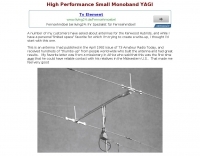
 A suitable high gain 70cms antenna for SOTA operation was sought that did not have the drawbacks of a long Yagi antenna, principally a narrow beamwidth and bandwidth.
 -

-
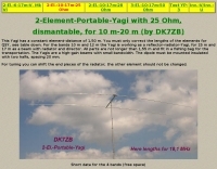 This Yagi has a constant element-distance of 1,50 m. You must only correct the lengths of the elements for QSY, see table down. For the bands 10 m and 12 m the Yagi is working as a reflector-radiator-Yagi, for 15 m and 17 m as a beam with radiator and director.
 -
 A 7 elements yagi beam monoband antenna for 14 Mhz by VE3GK
 -
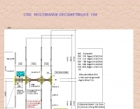 F6CHT plan for a multiband yagi antenna that covers 6 to 30 meters band in french
 -
 VHF Optimized Yagi Antenna for the 6-meter band (50 Mhz) by ON6MU
 -
 Located in France, DXBeam designs and manufactures a range of monoband, dual band and triband antennas, rotary dipoles, Moxons and Yagis
 -
 30/17/12 and 20/15/10-Meter Tribanders and a 40 meters inverted V wire yagi antenna
 -
 A monoband yagi for 14 MHz a PDF article from 73 amateur radio magazine by AB4GX
 -
 Antenna was designed for SO-50 satellite operation but can be used for any VHF/UHF activity. It's a mix of a Moxon Antenna and a Yagi antenna. It has gains 4 dBd on 2m and 6.5 dBd on 70cm bands and it is fed via single 50 Ohm cable.
 -
 AB4GX K4EAA Mononband yagi antenna for 20 Meters
 -
 An interesting article on building a 4 elements yagi antenna with gamma match for the 2 meter band. This article include two videos demonstrating assembling procedure by KG0ZZ
 -
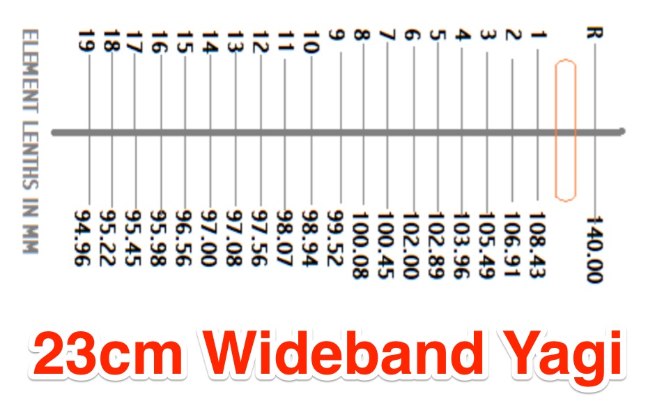
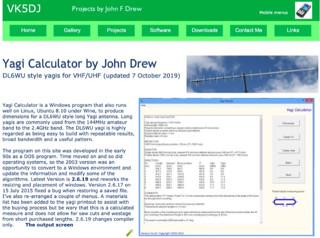 Yagi Calculator is a free Windows program that also runs well on Linux, Ubuntu 8.10 under Wine, to produce dimensions for a DL6WU style long Yagi antenna. Long yagis are commonly used from the 144MHz amateur band to the 2.4GHz band.
 -
 An homebrew crossed Yagi antenna for two meters band based on DK72B design with pictures, detailed description and tricks by Barry Zarucki M0DGQ
 -
 PA5DD version of the dual band yagi antenna for 50 and 70 Mhz
 -
 Dutch Antenna and Tower Manufacturers from Slimline Square Triangular Round Towers. Antennas production include Yagi Monoband/Dipole/HF Quad /50MHz and 70MHz Yagi-Quad, VHF-UHF yagi-Quad and Comby antennas VHF/UHF/SHF
 -
 A copper pipe Hentenna for 144 MHz. The Hentenna, a compact, high-gain loop antenna developed in Japan in the 1970s, offers approximately 5.1 dBd gain, comparable to a three-element Yagi. Adapted for 2 meters, it is crafted from copper pipe for simplicity, affordability, and broadband performance. Requiring no feed-point tuning, its construction involves soldering standard copper fittings. Installation demands non-conductive materials to minimize signal disruption. Versatile for vertical or horizontal polarization, it is ideal for FM, repeater, SSB, or CW applications. This design emphasizes practicality and performance for amateur radio enthusiasts
 -
 Demonstrates the design and construction of a 9-element Yagi antenna for the **70 cm band** (432 MHz), based on the DK7ZB concept. The resource details EZNEC+ calculations for a single antenna, providing gain, sidelobe suppression, and front-to-back ratio figures. It also presents a comprehensive analysis of stacking two such antennas, including optimal stacking distance (1000 mm) and the resulting performance enhancements for the stacked array, such as an increased gain of 17.03 dBi. The article includes detailed drawings, wire file dimensions in millimeters, and azimuth/elevation plots for both single and stacked configurations. Practical construction steps are documented with original photographs, illustrating element mounting, the **28 Ohm matching system** using two quarter-wave 75 Ohm transmission lines, and the critical N-connector wiring. It also covers the iterative process of fine-tuning the driven element length to achieve a return loss of 20 dB, validating the EZNEC+ simulation results with actual measurements.
 -
-
 Demonstrates the product line of _LZ Antenna Ltd._, a Bulgarian manufacturer specializing in amateur radio antennas and custom electronic devices. The company focuses on robust, high-quality HF multiband Yagi and vertical antennas, leveraging over 20 years of experience from founder Georgi Georgiev in radio amateur development. Featured models include the LZA 8-4, LZA-10-3, and the LZA-7-3A WRTC 2022, alongside various rotary dipoles like the LZA1 40/30m. Provides specifications for several Yagi antennas, such as the LZA-9-5, LZA-13-7, and LZA-6-3 (a 6-element, 3-band design). The company emphasizes applying "leading edge technology" to high-frequency communication equipment production, with products designed for durability and performance. The LZA-10-5 Yagi offers **12.5 dBi** gain on 10m, while the LZA-13-7 provides **13.2 dBi** on 20m, showcasing competitive gain figures for DXing and contesting.
 -
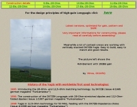 High gain, good pattern and acceptable bandwidth. These aims can be realized with a radiation-resistance of 25-35Ohms, because the 28-Ohm-feedpoint is very simple to match.
 -
 Presents the design and performance of a 4-element wire Yagi antenna for the 40-meter band, building upon VE3VN's earlier 3-element switchable wire Yagi. The resource details the antenna's evolution, highlighting the transition from a 3-element to a 4-element configuration and the resulting improvements in gain and front-to-back ratio. It provides specific insights into the antenna's construction and expected operational characteristics. VE3VN shares insights from field results, noting the antenna's performance on 40 meters. The discussion includes the antenna's pattern and matching characteristics, crucial for any DXer or contester looking to optimize their signal on this popular HF band. The author's experience with the previous 3-element design informs the enhancements made to this 4-element iteration. The article includes a visual representation of the antenna's current view, offering a practical perspective on its physical layout. It serves as a valuable reference for hams considering a directional wire antenna for 7 MHz operations, demonstrating a practical approach to achieving enhanced directivity and gain.
 -
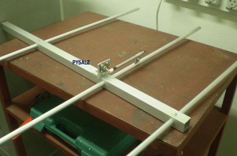 A 3 element yagi antenna project for the 144 MHz band by PY5ALZ in portuguese
 -
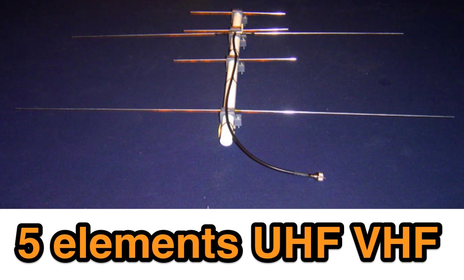 On this page is the design for Dual Band 2M / 70cm antenna with 3.2mm elements. The antenna has a 50 ohm designed driver. This Yagi has a unique element called a Open Sleeve
 -
 A triband VHF Yagi antenna for 6 m, 4 m and 2 m with one feed-point by DK7ZB
 -
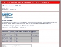 Christoph petermann's df9cy six element yagi antenna for six meter band
 -
 A project for a home made 5 element yagi-uda antenna for 2 meters, covering 144-148 MHz band by N1BMX
 -
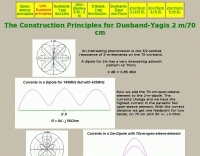 The Construction Principles for Duoband-Yagis 2m/70cm by DK7ZB
 -
 This document details the design and construction of a Vinecom 6N4 dual-band Yagi antenna for the 50MHz (6-meter) and 70MHz (4-meter) amateur radio bands. The antenna features 9 total elements (4 elements for 50MHz, 5 elements for 70MHz) on a 4.236-meter aluminum boom. Computer simulations using MMANA software predict 7.21 dBd gain on both bands with front-to-back ratios of 16.01dB (6m) and 15.37dB (4m). The design uses 12.7mm diameter elements mounted on a 32mm square boom, weighing 5.7kg total. Practical measurements with an MFJ-269 analyzer confirmed good SWR performance across both bands after element length adjustments.
 -
-
 Demonstrates the construction of a 144 MHz turnstile antenna, detailing its design for omnidirectional, horizontally polarized VHF operation. The resource outlines the physical dimensions and materials required, including specific lengths for the radiating elements and the use of _RG-58_ coaxial cable for phasing. It covers the assembly process, emphasizing the critical spacing and connection points to achieve the desired radiation pattern and impedance matching for the _2-meter band_. The article presents measured _SWR_ performance across the 144-146 MHz segment, showing a low SWR of 1.2:1 at 144.5 MHz, which is suitable for general VHF use. It compares the turnstile's performance to a 9-element Yagi, noting the turnstile's advantage in providing consistent signal strength from all directions without requiring a rotator. Practical application for local FM simplex and repeater operations is implied, offering a simple yet effective antenna solution for fixed or portable stations.
 -
 A Loop Fed Array Yagi antenna for 50 MHz featuring 11 dBi gain and 23 f/b ratio. In this excellent page the author even includes a detailed drawing in DWG format, with element lenght and spacing measures, in a separa file a full list of material list needed to build this yagi antenna including source and price, the EZnec file for this antenna plan, and a lot of pictures of this LFA Yagi for 50 Mhz. A ten page PDF file containing all infos, is also available to download.
 -
 The antenna is a VHF side is a 2m moxon, tuned on 145.825 MHz. The driven element of the moxon couples to a driven element for a 5 element 70cms Yagi, tuned on 436.5 MHz.
 -
 The _Italian VHF Beacons_ resource provides a detailed listing of active and QRT amateur radio beacons operating across VHF, UHF, and SHF bands within Italy. Each entry specifies the beacon's callsign (e.g., IQ1SP/B), operating frequency (e.g., 144.411 MHz), QTH locator (e.g., JN44VC), effective radiated power (ERP) in watts, and antenna configuration (e.g., Big Wheel, 4x Dipole, Yagi). This data is crucial for radio amateurs involved in propagation studies, equipment testing, and long-distance (DX) communication on these higher frequency bands, offering fixed signal sources for monitoring. This compilation, last updated in October 2005, serves as a historical snapshot of Italian beacon activity. For instance, it lists several 144 MHz beacons with ERPs ranging from **0.1W** to **10W**, and higher frequency beacons such as I8EMG/B on 1296.880 MHz and I3EME/B on 24192.132 MHz. The inclusion of QRT (Quiet Radio Teletype) status for many entries indicates the dynamic nature of beacon operations over time. Users can utilize this information to identify potential signal sources for band openings or to calibrate their receiving equipment against known transmissions.
 -
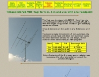 Triband DK7ZB VHF Yagi antenna for 6 m, 4 m and 2 m with a single feedpoint
 -
 This project details the construction of a **full-sized 40-meter vertical antenna**, born from a renewed interest in 7 MHz operation and a desire for improved effectiveness over simple dipoles. The author, K5DKZ, initially focused on VHF experimentation, which provided an inventory of aluminum tubing and fiberglass spreaders for this endeavor. Before this vertical, K5DKZ utilized an 80/40 meter inverted-vee trap dipole and a 40-meter broadband dipole, but now primarily uses a pair of full-sized, phased, quarter-wave verticals spaced 35 feet apart for serious 40-meter work. The construction involves a base-heavy design for stability, using a 44.5-inch section of 1-1/4 inch steel TV mast driven into 1-3/8 inch aluminum tubing, insulated by a 105-inch section of Schedule 40 PVC pipe. The assembly reaches 31 feet, close to the 32 feet required for a quarter-wavelength on 40 meters, with fine-tuning achieved by winding wire onto a fiberglass spreader. The design is explicitly presented as a foundation for a two-element 40-meter Yagi beam, outlining modifications like substituting aluminum for steel in the base and using an inductive hairpin match for the driven element. The article also discusses tuning considerations for a large 40-meter beam, noting the 100 to 200 kHz upward frequency shift when raised, and suggesting methods for installation on a tower. The author emphasizes the cost-effectiveness and good performance of the monopole approach, especially when multiple verticals are needed.
 -
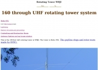 This is the 195-foot tall rotating Rohn 55G tower at W8JI with yagis for 40 20 15 and 6 meter bands.
 -
 An homebrew project for a 3 element coil-loaded Yagi beam antenna for 40 Meter band
 -
 A 5 elements homemade DK7ZB yagi antenna for 4 meters band based on a 50MHz TONNA
 -
 Demonstrates the adaptation and construction of a 7-element DK7ZB Yagi antenna for the 4-meter band (70 MHz), utilizing components from a defunct 2-meter CUE DEE Yagi. The resource details the modifications made to the original DK7ZB design to fit the shorter CUE DEE boom length, specifically adjusting element lengths for 6mm rod elements while reusing existing mounting holes for the reflector and last director. It provides precise element lengths for the reflector, dipole (12mm aluminum tube), and five directors, along with a note on cutting elements for transport. The article includes a 4NEC2 simulation file for performance analysis and an SWR plot, confirming the antenna's electrical characteristics. It also specifies the calculation for the quarter-wavelength matching cable using SAT752F coaxial cable, resulting in a 909mm length. Practical application is shown with the finished antenna in operation at JO20XC, listing several activated Maidenhead squares such as JO56PA and JP40KS, validating its effectiveness for portable 70 MHz operations.
 -
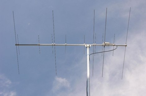
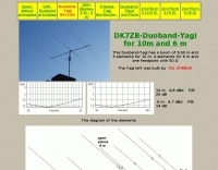 This Duoband-Yagi has a boom of 3.60 m and 3 elements for 10 m 4 elements for 6 m and one feedpoint with 50 Ohm
 -
 The 10-minute, 25-second video demonstrates making a QSO via the VO-52 amateur radio satellite, focusing on real-time Doppler shift correction. It features Simon, 2E0HTS, operating a Yaesu FT-847 transceiver and a homebrew dual-band Yagi antenna, specifically a 10-element 435 MHz Yagi for uplink and an IO Loop for 145 MHz downlink. The video visually details the operator's technique for continuously adjusting the uplink frequency to compensate for the satellite's changing velocity relative to the ground station, a critical aspect of successful satellite communication. The demonstration highlights the practical application of Doppler compensation, showing the operator tuning the transmit frequency to maintain a stable received signal from the satellite. This approach contrasts with systems employing automatic Doppler correction or full-duplex operation, providing insight into manual frequency management for satellite passes. The video serves as a direct, observational guide for hams interested in LEO satellite operations, particularly those using non-tracking, manually tuned setups.
 -
 EF0603S is a 3 element portable yagi antenna for six meters band by YU7EF
 -
 In this PDF article Zack Lau describe how to homebrew a four element yagi beam antenna for 50 MHz band, including how to build mounting blocks and tubing clamps to hold elements.
 -
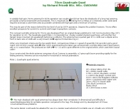
 Dimensions and EZNEC plots for a 2 Element 30 meter Yagi antenna with 28 Ohm featuring 4.3 dBd Gain and a 16dB F/B with a good bandwidth.
 -
 A 5 element yagi beam antenna for ten meters band with full dimentsions, eznec file and coax match informations for 50 ohms feed line
 -
 An homebrew project for a 4 elements yagi monoband antenna for the 10 meters by 9M2MSO
 -
 An high gain long yagi antenna, seven elements, for six meters band
 -
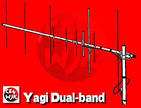
 Yagi with 5 Elements on 2 m, 8 Elements on 70cm and one Feedpoint by DK7ZB
 -
 Based on a simple project based on a 2 elements Yagi for 20m band, and then becomed a triband yagi with a open-sleeve feed system