Search results
Query: edi file
Links: 136 | Categories: 0
-
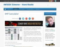 ERP Calculator is an Amateur Radio software utility designed to perform a side-by-side comparison of two Ham Radio antenna systems. ERP Calculator comes pre-programmed with data files including published data for several popular brands and types of coax cable as well as several popular antenna system brands and models. ERP Calculator displays values of ERP, Antenna Power Gain, Antenna Feed point Power, Antenna System Gain in dB, Antenna Gain in dBd, SWR Attenuation in dB, SWR Power Attenuation, Coax Loss in dB, and Coax Power Loss
 -
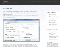 Lets you listen to your scanner across your own network, or via the internet. Shoutcast/ICEcast compatible broadcasting for Uniden and GRE scanners. Broadcast your audio from your PC. ScannerCast is a specialized broadcasting solution that enables users to stream scanner audio feeds over the internet. This software supports both Uniden and GRE scanner models with tag information capability, while providing audio-only functionality for other scanners. Compatible with standard streaming protocols, ScannerCast allows remote listening via common media players without requiring specialized client software. The program features customizable tag display, adjustable bit rates, and seamless integration with Radio Reference. Its efficient design replaces multiple legacy applications while improving tag/audio synchronization. ScannerCast operates efficiently across various Windows environments, making remote scanner monitoring accessible from any location with internet connectivity. Scannercast is no more supported or developed by it's author.
 -
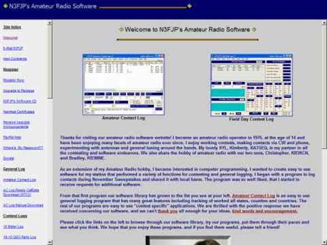 N3FJP's ARRL Field Day Contest Log 6.6.10 is a dedicated software solution for Windows 7 through Windows 11, specifically tailored for the annual ARRL Field Day event in June. This program provides essential contesting features such as duplicate checking, including partials, and a dynamic list of sections that change color upon being worked. It seamlessly interfaces with popular digital mode software like WSJT-X, Fldigi, and JTAlert via API, and supports rig control for most Elecraft, Icom, Kenwood, and Yaesu transceivers. The software also generates computer-generated CW via serial port or Winkeyer, plays wave files, and offers DX spotting capabilities. Operators can leverage its fully networkable design to allow multiple PCs to update a single log file simultaneously, enhancing club operations during Field Day. The program outputs ASCII log, dupe, and summary files for contest submission and provides real-time statistics. A quick start video is available to guide new users through the basics of the software. Registration for permanent use costs $8.99, or it can be obtained as part of the N3FJP Software Package, which includes over one hundred amateur radio programs for a one-time fee of $59.99.
 -
 A 20-meter Moxon antenna design provides a compact directional solution for the 14 MHz band, achieving approximately **5.5 dBi** of forward gain and a front-to-back ratio exceeding 20 dB. This rectangular wire array, consisting of a driven element and a reflector, offers a smaller footprint than a traditional 2-element Yagi, making it suitable for space-constrained installations. Construction details focus on specific dimensions for the wire elements, fed with 50-ohm coaxial cable. The _Moxon rectangle_ inherently delivers wide bandwidth and a clean radiation pattern, simplifying tuning with a relatively low SWR across the entire 20-meter band. Its robust performance makes it a practical choice for both fixed stations with limited tower space and portable _DXing_ operations. The design's characteristics are particularly beneficial for contesting and long-haul communications on 20 meters.
 -
 Constructing a high-gain, compact antenna for 2 meters often involves balancing theoretical performance with practical build challenges. WB8AHT recounts his journey in building a 6-element _Super Duper Moxon_ antenna for 144 MHz, inspired by designs from M0PXS and GW3YDX. He initially encountered discrepancies in published dimensions for the _HAARP Antenna_ and the _Super Moxon_, leading to on-air SWR issues and suboptimal performance. His methodical approach involved cross-referencing, direct communication with Phil Simpson (M0PXS), and iterative adjustments to element lengths based on observed results and a _SARK-110 Antenna Analyzer_ scan. After modifying the reflector/driven element and third director dimensions, the antenna achieved a respectable 1.35:1 SWR at 144.200 MHz. Field testing with 50 watts yielded contacts up to 500 miles, suggesting performance close to the 15 dBi gain predicted by _4NEC2_ software, despite its compact 40-inch boom. The article includes specific construction notes, such as tubing sizes (1/2-inch and 3/8-inch aluminum) and feedpoint spacing (50mm). The author's experience highlights the importance of real-world validation for antenna designs, even those with strong theoretical backing. He provides a table of tubing lengths for 6m, 4m, and 2m versions, along with his final, optimized dimensions, offering a practical blueprint for fellow hams interested in replicating or further experimenting with this high-performance, small-footprint VHF antenna.
 -
 A comprehensive collection of DX information consisting of news, audio files, station profiles, equipment articles, discussion forum, DXpedition reports and logs for mediumwave, shortwave and FM DXers.
 -
 The resource provides an in-depth analysis of the W6NL 40m _Moxon Yagi_ antenna, utilizing a NEC-2 model to simulate its performance. It details the antenna's design parameters, including element lengths and spacing, and explores critical operational aspects such as feedpoint impedance, SWR across the 40-meter band, and radiation patterns. The document systematically presents the model's setup and the methodology for evaluating the antenna's behavior in different environments, including free space and over real ground. Performance data derived from the NEC-2 model illustrates the antenna's forward gain, front-to-back ratio, and beamwidth. For instance, the model predicts a free-space gain of approximately **6.5 dBi** and a front-to-back ratio exceeding **20 dB** at resonance. Comparisons are drawn between free-space performance and operation at various heights above average ground, demonstrating the impact of ground proximity on take-off angle and overall efficiency. The analysis also touches upon the antenna's bandwidth characteristics, indicating its suitability for the entire 40-meter band with acceptable SWR.
 -
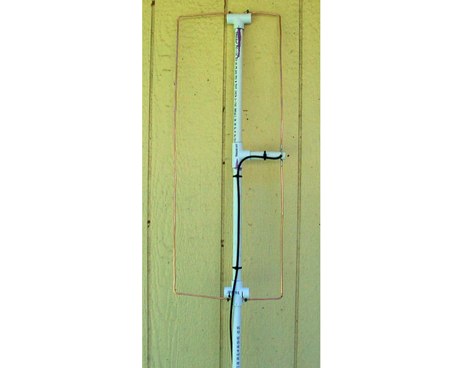 Presents the construction and performance characteristics of a **2-meter vertical Moxon** antenna designed by WB5CXC. The antenna utilizes 1/2-inch PVC and #6 copper ground wire for its physical structure. Performance data includes measured front-to-back ratio using a local repeater, demonstrating significant signal attenuation when rotated. The resource provides **antenna pattern** plots, with blue tracing the design at 146 MHz and red indicating performance at 148 MHz. Gain and SWR plots are also included, alongside a detailed diagram of the antenna's physical layout. The design emphasizes a good front-to-back ratio, aligning with modeling predictions.
 -
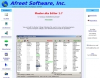 Freeware windows program by VE3NEA that allow to view and edit the Master Callsign Database file used in many contesting programs, import and export callsigns, auto-download announced DX operations.
 -
 The PDF document, titled "J-Poles," presents various J-pole antenna designs covering the 50 MHz to 450 MHz frequency range. It includes construction details for several specific bands, such as a 6-meter J-pole, a 2-meter J-pole, and a 70-centimeter J-pole. The content outlines the fundamental principles of J-pole operation, including the quarter-wave radiator and half-wave matching stub. Each design features specific dimensions for elements like the radiator length, stub length, and spacing, often expressed in inches. The document also discusses feeding arrangements and impedance matching considerations inherent to J-pole antennas. It provides practical guidance for homebrewing these antennas using common materials like copper pipe or wire elements. The resource offers insights into the advantages of J-poles, such as their omnidirectional pattern and ease of construction, making it a practical reference for radio amateurs interested in VHF/UHF antenna projects.
 -
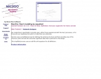 Powerful antenna modeling tool using NEC 2 computing engine. Nec2 specifically provide users, either those experienced with the Nec2 processes, or for those who are neophytes but want to model their own antennas. Nec2Go uses a simplified process for defining the antenna structure and then providing view of the structure, plots (2D and 3D) and other significant data that is pertinent to the design. This simplified process uses an edit file with equations for all definitions.
 -
 The resource details the construction of a 6-meter _Moxon_ antenna, presenting two distinct versions: one horizontally polarized for 50-51 MHz CW/SSB and another vertically polarized for 52-54 MHz FM. It specifies the use of 5/8 inch OD and 1/2 inch OD aluminum tubing, with 3/8 inch OD solid aluminum for corners, and provides a comprehensive material cutting schedule. The design aims for robust, portable construction, with all materials costing under $100. Detailed drawings and EZNEC models are referenced for precise dimensions and assembly, ensuring accurate element spacing and impedance matching. The EZNEC model for the H-POL version predicts a gain of **11 dBi** and a front-to-back ratio of **25 dB** at 50.5 MHz, while the V-POL version shows a gain of **6.7 dBi** and a front-to-back ratio of **36 dB** at 53 MHz. The article includes practical SWR measurement advice, noting the impact of coax length and loss on analyzer readings. Field tests during a tropical storm demonstrated the antenna's durability and performance, yielding numerous contacts across significant distances, including California, Colorado, and Texas, on SSB and PSK.
 -

-
 TAHO.EXE, an open-source software, facilitates the creation of APRS maps for _UI-View_ by converting free data from _OpenStreetMap_ into the required *.JPG and *.INF file formats. This utility, developed by Dimitri Junker with specific UI-View format support added at the request of HB9DTX, streamlines the process of integrating detailed geographical information into the _UI-View_ platform. It operates on Windows, generating map files with border coordinates in just a few clicks, eliminating the tedious manual creation of *.INF files for custom maps. This converter allows UI-View users to leverage the continuously updated and community-contributed data of OpenStreetMap, which often surpasses commercial map quality in specific regions. The process is straightforward, with a detailed step-by-step guide available on the OpenStreetMap wiki, translated into French and German. TAHO.EXE significantly enhances the utility of UI-View by providing a readily accessible and continuously improving source of detailed, current geographical maps for displaying APRS station positions and objects.
 -
 This document details the design and construction of a Vinecom 6N4 dual-band Yagi antenna for the 50MHz (6-meter) and 70MHz (4-meter) amateur radio bands. The antenna features 9 total elements (4 elements for 50MHz, 5 elements for 70MHz) on a 4.236-meter aluminum boom. Computer simulations using MMANA software predict 7.21 dBd gain on both bands with front-to-back ratios of 16.01dB (6m) and 15.37dB (4m). The design uses 12.7mm diameter elements mounted on a 32mm square boom, weighing 5.7kg total. Practical measurements with an MFJ-269 analyzer confirmed good SWR performance across both bands after element length adjustments.
 -
 Presents the construction of a 6-meter (50 MHz) Moxon wire beam antenna, detailing the use of #14 AWG THNN stranded wire and a treated wood frame. It covers the assembly of a galvanized pipe mast, emphasizing the use of pipe sleeves for joint reinforcement over threaded couplers to prevent breakage during raising and lowering operations. The resource also describes the integration of a 1:1 current balun, rated for 50-54 MHz, and the use of RG-8X coax for the transmission line, recommending low-loss alternatives like Belden 9913-7F. Further, it outlines a manual rotation mechanism using pipe hanger clamps and carriage bolts for true North orientation, incorporating magnetic declination calculations from NOAA. The antenna's performance is discussed, noting good gain and take-off angle, with SWR tuning facilitated by a Palstar AT-500 manual tuner. An EZNEC+ 5.054 model for the antenna is available for download, alongside predicted radiation patterns and SWR curves, compared with actual AIM-4170C measurements.
 -
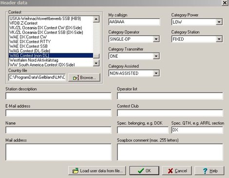 LM is a program to edit contest logs afterwards, a so-called contest post processor. With help of LM you can convert row data to many different file formats. Allow a quick input interface, and contest score for several contest. Can import & export a batch of logs and to create result lists.
 -
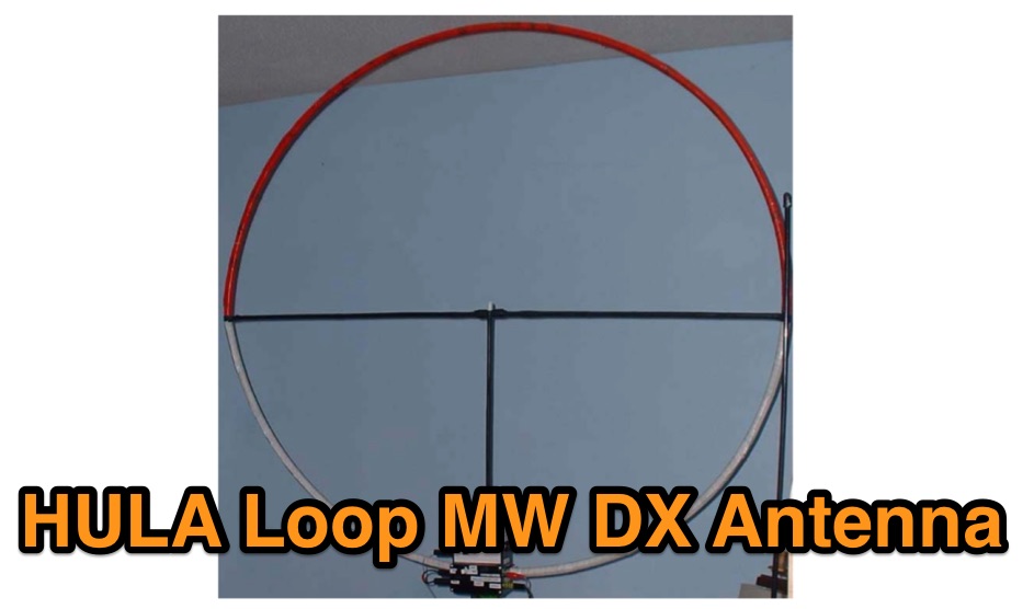 An excellently presented article on the design and construction of a medium wave DX Antenna
 -
 This program is used for the ICOM IC-746PRO, IC-7400.You can edit all the setting and write it to file for later use. Runs on Windows Linux and MacOSx
 -
 The ZS6BKW multiband antenna, an optimized variant of the classic G5RV, features a 102-foot (31.1 m) horizontal span and a 39.1-foot ladder line matching section. This design, derived by G0GSF (formerly ZS6BKW) in the early 1980s using computer programs and _Smith charts_, aims for improved SWR across multiple HF bands compared to its predecessor. Construction details specify Wireman 554 ladder line and #14 AWG THHN copper wire for the radiators, with precise instructions for determining the velocity factor (VF) of the ladder line using an antenna analyzer or dip meter, ensuring accurate physical length for the matching section. The radiator length is electrically 1.35 wavelengths for the 20-meter band, requiring careful trimming during tuning. Field measurements with an _AIM-4170C_ analyzer by KI4PMI and NC4FB demonstrated good SWR curves and bandwidth on 6, 10, 12, 17, 20, and 40 meters. The antenna was deemed unusable on 15 and 30 meters due to very high SWR, but an LDG AT-100PRO autotuner successfully brought 6 and 80 meters into tune. Contacts were made on 80, 40, 20, and 17 meters, including a **17-meter** contact to Spain. EZNEC models for 80-6 meters are provided, along with an AutoEZ model by AC6LA, which predicted good SWR for 80-10 meters. W5DXP's modifications for an all-band HF ZS6BKW are also referenced.
 -
 A Variable Base-Loading-Coil provides a practical solution for optimizing HF mobile whip performance across multiple bands. The design, as presented by VK4ADC, details a coil wound on a 50mm PVC former, utilizing 1.6mm enamelled copper wire for robust construction. This approach allows for precise tuning, a critical factor in achieving efficient radiation from a mobile setup, where antenna length is often compromised. My own field experience with similar base-loaded whips confirms the importance of a well-designed loading coil for maximizing signal strength and minimizing SWR. The VK4ADC design incorporates a sliding contact, enabling continuous adjustment, which is superior to fixed taps for fine-tuning resonance on the fly. This variable inductance allows the operator to quickly adapt the antenna to different HF segments, from 80 meters up to 10 meters, without needing to swap out multiple coils. The document includes specific winding data, such as the number of turns per inch and the overall length of the coil, which are essential for replication. It also touches upon the mechanical aspects of integrating the coil with a standard mobile whip, ensuring a stable and weather-resistant assembly for reliable operation during mobile DXing or casual rag-chewing.
 -
 Lights on why 160 meters is so unpredictable and what is being done to reveal its secrets
 -
 The design and feeding of driven elements for VHF/UHF Yagi antennas , modeling, observations and some case studies by Graham Daubney F/G8MBI
 -
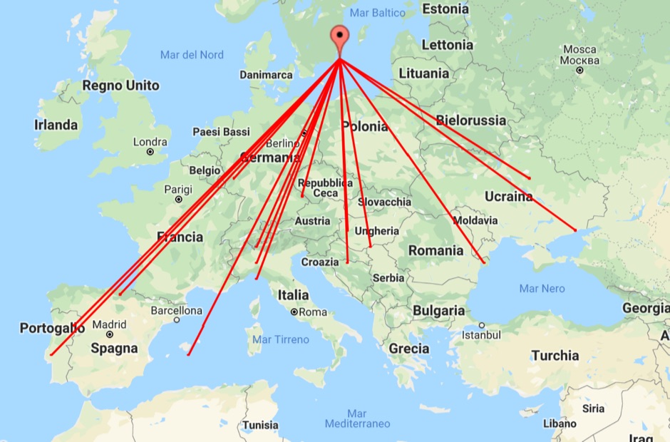 With this tool it is possible to create QSO maps overlay on Google maps there each QSO get a line from the home location to each DX location. An EDI logbook file is used as input. The creation will only use complete locator in the 6 characters format.
 -
 The ZS6BKW multi-band antenna, an optimized variant of the classic G5RV, is presented with detailed construction and tuning instructions. This resource outlines the antenna's design principles, which were developed by _Brian Austin (G0GSF)_ using computer programs and Smith charts to achieve optimal dimensions. It provides specific guidance on calculating and adjusting the lengths of the radiators (L1) and the matching ladder line (L2), emphasizing the critical role of velocity factor (VF) in achieving resonance. The article includes a step-by-step procedure for empirically determining the VF of ladder line using an antenna analyzer, ensuring accurate physical lengths for the matching section. It details the tuning process for the radiators, offering practical tips for incremental adjustments to achieve the best SWR curve. The resource presents SWR measurement results obtained with an _AIM-4170C_ analyzer across multiple bands, alongside predicted SWR graphs from an AutoEZ model. It confirms successful contacts on 80, 40, 20, and 17 meters, including a **17-meter DX contact** to Italy. EZNEC and AutoEZ models for the ZS6BKW antenna, covering 80 through 6 meters, are provided for download, allowing further analysis and customization. The document specifies component details, such as the use of Wireman 554 ladder line and #14 AWG THHN copper wire, and discusses the antenna's performance characteristics, noting high SWR on 15 and 30 meters but successful tuning on 6 and 80 meters with an external tuner.
 -
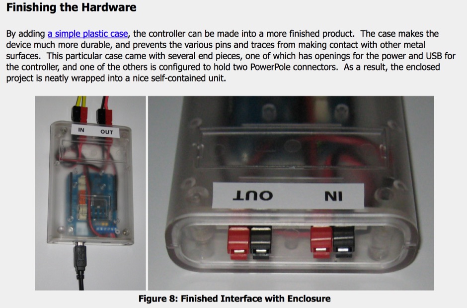 A system designed to automatically tune small transmitting magnetic loop antennas, particularly beneficial for **contest operations** where rapid frequency changes are common. The core of the system involves a PC-based control application, AutoCap, written in C#, which monitors antenna SWR via an external meter and commands a motor interface to adjust the loop's variable capacitor. The software is compatible with Windows and Linux via the Mono framework, offering a graphical user interface for monitoring system status, SWR, power, and motor commands. Key components include one or more magnetic loop antennas equipped with DC or stepper motors for capacitor adjustment, an SWR meter with data output (such as the Telepost LP-100A or a homebrew serial/USB SWR meter), the AutoCap PC software, and a motor interface. The most effective motor interface utilizes an **Arduino-based controller** with custom firmware, providing precise control over both simple DC motors and stepper motors, and supporting features like motor braking for finer adjustments. The system allows for configurable SWR thresholds, pulse widths, and motor effort settings to optimize tuning speed and resolution. Optional radio integration provides frequency hints, enabling the algorithm to learn the relationship between motor actions and resonant frequency, thereby speeding up initial tuning responses. The software also supports antenna profiles, allowing operators to save and recall specific configurations for different loops, including accumulated frequency hint data.
 -
 A special edition of AALog, optimized for the use in a lot of different contests. It can export file in Cabrillo, .SUM and .ALL files, ADIF. To use this program in CW and digital modes you need to use CwType and TrueTTY.
 -
 Ten essential tips and truisms for understanding HF antenna: Non-resonant wire dipole antennas fed with open-wire line and an antenna tuner can function effectively as multiband antennas, as detailed in "The Classic Multiband Dipole Antenna" by WB8IMY in March 2004 QST. Coaxial cable, unlike balanced parallel-wire feed lines, can cause RF to travel on the outer shield braid, leading to RF feedback to the station; a 1:1 balun at the dipole center can mitigate this by isolating the unbalanced coaxial feed line. Antenna gain is achieved by shaping and directing RF energy, with beam antennas concentrating power in a specific direction, and wire antennas also exhibiting shaped radiation patterns. An antenna tuner's primary role is to match the transceiver's 50-ohm output to the antenna system's impedance, allowing modern transceivers to deliver full power. Wire antennas do not always require center feeding; end-fed long wires or off-center-fed dipoles (like the Windom) can be used, though they often necessitate an antenna tuner and a counterpoise or radial network. Dipole antennas do not need to be perfectly horizontal; their legs can be bent or inclined, which affects feed point impedance and may require SWR experimentation with coaxial feed. Vertical antennas shorter than a half wavelength require an efficient ground system, typically comprising elevated or buried radial wires, with more radials generally leading to better efficiency. A 1:1 SWR indicates an impedance match but does not guarantee antenna efficiency; an inefficient vertical antenna with a poor ground system can show a low SWR while wasting most RF as heat. Investing in high-quality, low-loss feed line, especially coaxial cable, is crucial for maximizing RF signal transfer and overall antenna system performance.
 -
 Tencom, located near Toledo, Ohio is dedicated to the pultrusion of fiberglass composite products. This includes solid rods, conductor rods, tubes and a variety of custom profiles.
 -
 We are the premier Amateur Radio Club in the Edinburgh area, since our formation in 1984 we have done much to raise the profile of our hobby in the area.
 -
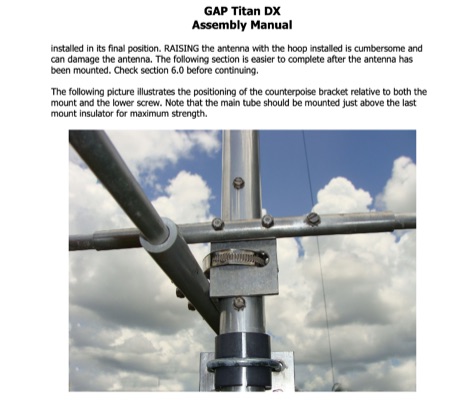 This manual is an edited version of the GAP supplied document, complete with diagrams, pictures and assembling notes by Mitch Baum AE2A. This is 29 pages document in PDF Format.
 -
 Presents a detailed resource for DXers interested in Non-Directional Radiobeacons (NDBs), MF, HF, and VHF propagation beacons, and various other radiobeacon types. The site offers access to downloadable information files, including an Abbreviations List, NDB List Country List, and NDB Publications List, which serve as foundational materials for newcomers to the hobby of beacon monitoring and DXing. It covers specialized topics such as DGPS beacons, GMDSS DSC mode, and NAVTEX mode, with dedicated sections providing in-depth explanations. A Beacon Photo Gallery showcases diverse radiobeacon types from around the globe, offering visual context for different systems encountered in the field. The platform also facilitates participation in unique monthly Coordinated Listening Events (CLEs), providing guidelines and schedules for these activities. The resource outlines various associated Groups.io lists, including the primary NDB List for radiobeacons (NDBs, Propagation Beacons, VOR systems), the DGPS List for DGPS DXing, Time Signals, LORAN, and WeFAX modes, and specialist groups like NavtexDX and DSC List for GMDSS-DSC. It details how to join these communities for further engagement and information exchange.
 -
 Contains stories, pictures, audio files of all previous expeditions and current ones.
 -
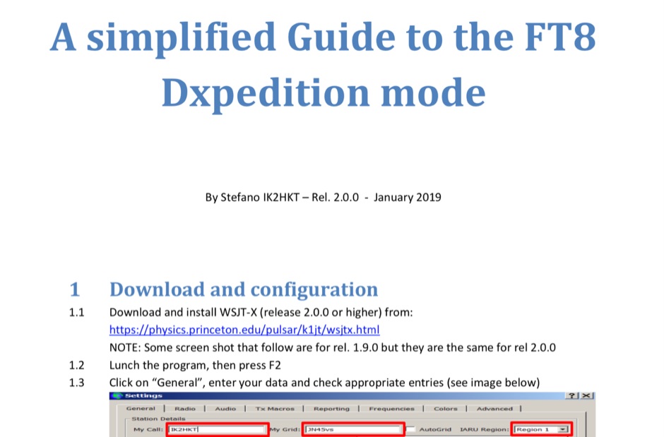 A simplified Guide to the FT8. Dxpedition mode. By Stefano IK2HKT – Rel. 2.0.0 - January 2019. This document explains how to configure WSJT to work on F/H mode DXPedtions, how to operate and make a call to a dxpedition calling CQ in FT8 Fox Mode.
 -
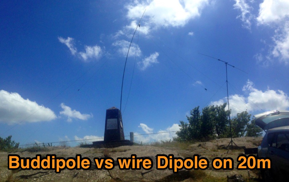 During a club's "Filetto Day" event, a comparative field test was conducted between a **Buddipole** antenna and a homemade 20/40-meter wire dipole. The author, IW5EDI, performed this personal evaluation from a mountain top at 1500 meters above sea level, utilizing a Yaesu FT-857D transceiver to switch between antennas. The observations on the 20-meter band indicated that the wire dipole consistently delivered significantly stronger signals compared to the Buddipole. Additionally, the Buddipole exhibited higher levels of **QRM** during the listening tests. The commercial Buddipole, known for its multiband capability and compact size with a self-supporting tripod, was contrasted with the simpler, larger wire dipole, which required a fiberglass fish pole for support. This direct comparison highlights practical differences in performance and deployment between a popular portable commercial antenna and a basic wire antenna in a real-world operating environment.
 -
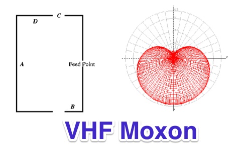 Constructing a 2-meter Moxon antenna for MURS channels, this resource details the antenna's geometry and expected radiation pattern. The design, optimized for low SWR, high gain, and front-to-back ratio on the first three MURS channels, uses 1/8-inch bronze brazing rod for elements. Author John E. Davis provides specific geometric parameters (A, B, C, D dimensions) rounded to the nearest 16th of an inch, along with a link to the final _.nec_ file for further analysis. Performance results show the attic-mounted Moxon performs well on the 2-meter band, despite its MURS optimization, with measured SWR plots provided. NEC-2 modeling predicts over 6 dBi gain and 40 dBi front-to-back ratio in free space. The author compares its directional performance to a _J-pole_ antenna, demonstrating substantially better signal strength for a nearby repeater when the Moxon is pointed in its general direction, confirming its superior gain and directivity.
 -
 This document is a must read for anyone considering building a good low cost HF multi-band antenna system. The author combine in this document four important ingredients to produce simple but effective antenna system, like antennas of non resonant length, line attenuation, the transmatch and the balun
 -
 A free PDF from NASA about cubesat. Basic Concepts and Processes for First-Time CubeSat Developers. A great introduction document dedicated to Cubseat developers.
 -
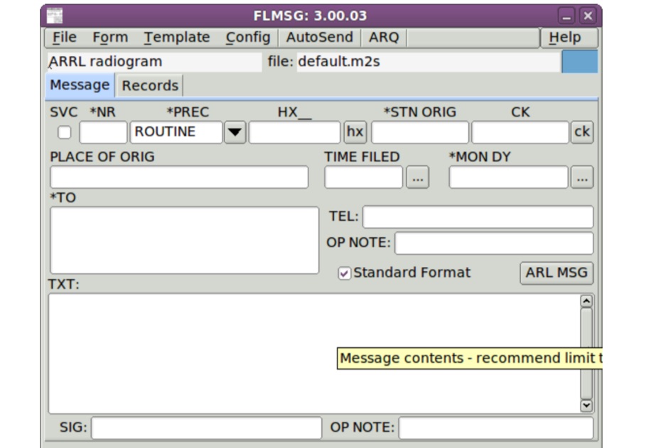 FLMSG is a simple forms management editor for the amateur radio supported standard message formats. Form data can be transferred between computers either using standard internet email or via radio frequency broadcasts typically made by an amateur radio operator on your behalf.
 -
 High Speed Multimedia Radio Introduction by ARRL Working Group Chairman. Report of the High Speed Multimedia (HSMM) Working Group ARRL Board of Directors 2006 Annual Meeting January 22, 2004
 -
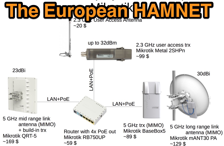 A presentatio about the European HamNet, a large scale high speed amateur radio multimedia network based on commercial wireless devices using mainly the 6cm band
 -
 This PDF File include the serial commands to program and control the TH-G71. Should work with TH-D7 series too
 -
 The MMMonVHF database, curated by DL8EBW, currently lists 63,455 entries for VHF operators, providing a searchable resource for locating stations active on 144 MHz and higher bands. Operators can register their callsigns to be included, with specific criteria such as participation in _MS_ (Meteor Scatter), _WSJT_ modes, or _EME_ (Earth-Moon-Earth) operations required for inclusion in the `call3.txt` file. This resource facilitates VHF DX expeditions and contest planning by allowing users to identify potential contacts within a geographical area. The database supports various VHF/UHF operating modes, including those focused on weak signal propagation. Statistical data regarding the database entries is also presented, offering insights into the distribution of registered VHF activity.
 -
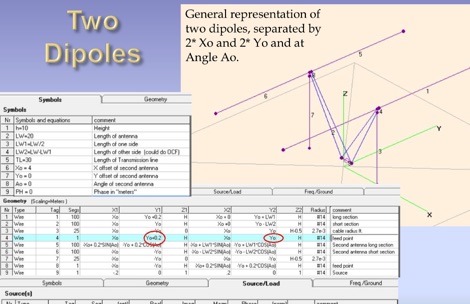 Presentation about Practical Antenna Modeling Using the NEC Codes with examples of HF wire antennas and 4NEC2. How to define and edit the models, Running the simulations, Work some examples, Variables usage, Deal with Feed Lines and ground
 -
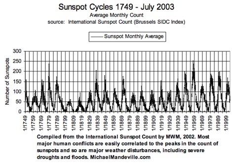 An article edited and published by Michael Mandeville on correlation of sunspot peaks and global events, like recessions or human conflicts. This document include solar cycle charts since Solar Cycle 1749-1751
 -
 First released around 1995 and significantly redesigned as QWTelnet 2, this software provides a dedicated interface for monitoring DX-Cluster traffic via Telnet. It integrates a **SOTAwatch parser** with configurable audio alerts, allowing operators to receive notifications for specific search patterns in DX-Cluster remarks without constant screen attention. The application also supports parsing for **GMAwatch (German Mountain Award)**, providing alerts for German Mountain Award activations. QWTelnet 2.4.0, released on 07-APR-2012, runs on Windows (tested on W7) and is distributed as a ZIP file containing the `qwtelnet.exe` executable. It does not require a formal installation process; users simply extract and run the program. The software can display DX information for single bands, integrate with the Reverse Beacon Network, and link to external web resources for DXCC and SOTA information. It also supports local reference files for IOTA, WFF, and RDA awards, which users must source and place in the `qwtelnet/files` directory. For IOTA data, users can convert `IOTA.CSV` from UCX-Log or `DX4WIN_IOTA.TXT` into `iota.csv`. WFF and RDA reference files are directly sourced from their respective websites.
 -
 A complete guide for newcomers edited by the Radio Amateur Society of Australia Inc. This free PDF includes several basic articles for new hams, with particular reference to Australian regulations, but is however a good guide for those who are aproaching the hobby worldwide.
 -
 About experiments and measurements on loading coils using net standing wave current
 -
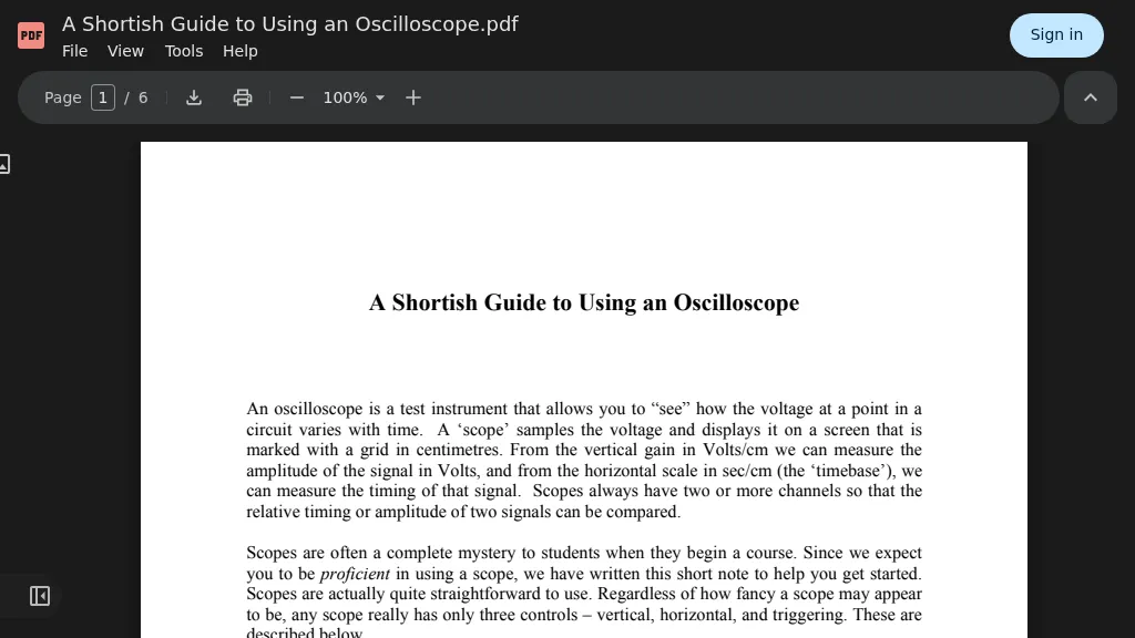 The "Shortish Guide to Using an Oscilloscope" elucidates the fundamental operation of oscilloscopes, detailing the purpose and function of vertical, horizontal, and triggering controls. It explains how vertical gain in Volts/cm and horizontal scale in sec/cm enable measurement of signal amplitude and timing, respectively. The resource differentiates between analog and digital scopes, noting that digital scopes often feature "soft" controls and are inherently storage scopes capable of capturing non-repetitive events. The guide dedicates a significant section to the critical role of oscilloscope probes, emphasizing their design to transmit waveforms without distortion or added noise. It explains the concept of a 10x passive scope probe, which reduces circuit loading by a factor of ten and eliminates waveform distortion through probe compensation, typically adjusted using a 1kHz square wave reference output. The document also provides practical advice on probe care and compensation procedures. Further sections address grounding considerations, explaining how a scope measures voltage relative to its chassis ground, which is tied to the protective earth. It offers troubleshooting steps for a blank screen and outlines essential good practices, such as checking input gain and probe attenuation, while explicitly warning against misusing probes or connecting the ground clip to mains voltage.
 -
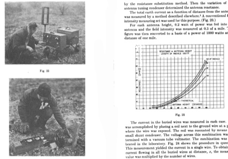 A classic document originally presented in Proceedings of the Institute of Radio Engineers in 1937 and is, still today, the standard referenced by the FCC, text books and many amateur radio publications.