Search results
Query: ground system
Links: 76 | Categories: 1
Categories
-
 This article presents an innovative homebrew antenna design utilizing surplus ladder line as a receiving antenna for HF and MF bands. The Ladder Line Antenna (LLA) transforms standard 450-ohm ladder line into a directional, bidirectional, or omnidirectional antenna system through different termination methods. The design, which requires minimal space and height, achieves 6-10dB front-to-back ratio on 40-160m bands using a 33-foot length. This DIY wire antenna project offers an efficient, low-profile solution for amateur radio operators, featuring broadband operation without ground radials and easy installation below fence height.
 -
 The resource, "Conventional Use of Transmission Line," meticulously details the operational principles of transmission lines, emphasizing the Transverse Electromagnetic (TEM) mode of energy transfer. It clarifies that for a line to function purely as a transmission line, all currents must be confined internally, with external fields ideally zero. The discussion differentiates between balanced and unbalanced lines, asserting that while both require equal and opposite currents within the conductors, the key distinction lies in the voltage relationship of each conductor to the surrounding environment. It highlights that a good antenna pattern does not inherently confirm proper feeder balance, and that common-mode currents can lead to RF in the shack and increased noise levels, even without pattern distortion. The article further explains that a transmission line can become a radiating conductor if energy is applied in a non-TEM mode, leading to common-mode issues. It cites classic texts like Jordan and Balmain's "_Electromagnetic Waves and Radiating Systems_" and Kraus's "_Antennas_" to support its definitions of TEM mode operation. The content also explores non-transmission line applications of parallel or concentric conductors, such as _coaxial dipoles_ and _folded dipoles_, which intentionally operate in non-TEM modes for antenna functionality. The author, _W8JI_, stresses that simply measuring equal currents is insufficient to confirm a balanced feeder; phase and voltage balance to ground are equally critical.
 -
 AN-SOF is a professional comprehensive software tool for the modeling and simulation of antenna systems. AS-SOF allows to describe antenna geometry, Choose construction materials, Describe the environment and ground conditions, Describe the antenna height above ground, Analize radiation pattern and front-to-back ratio, Plot directivity and gain, Analize input impedance and VSWR,Predict antenna bandwidth
 -
 Operating an amateur radio club, VE2CEV details its activities, including regular meetings and a significant project involving the construction of a **satellite ground station**. The resource outlines the project's inception, team formation, equipment acquisition, and the physical installation of antennas and rotator systems. It specifically mentions the use of a dual-axis AZ/EL rotator and antennas for VHF, UHF, and SHF (2 meters, 70 centimeters, and 13 centimeters), along with the strategic use of **Heliax cables** to minimize RF signal loss. The club also provides information on its interconnected repeater network covering southwestern Montérégie. The content highlights the practical application of the satellite station for communicating via amateur satellites and the International Space Station (ISS). It details the collaborative effort of members in securing a powerful Linux server, negotiating antenna installation with local authorities, and the precise alignment of antennas. The club emphasizes its role in guiding new amateurs, offering demonstrations, and potentially organizing courses, indicating a focus on community engagement and technical education within the amateur radio hobby.
 -
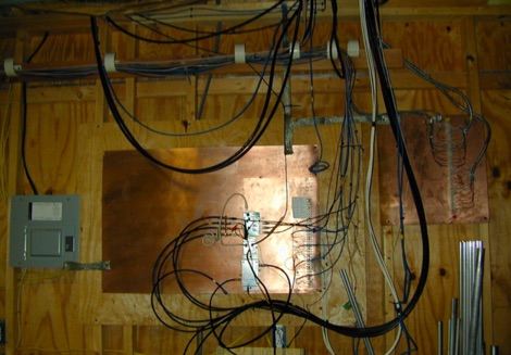 Solution for stations located at secondo floor or higher. Lead lengths to the grounding system are much too long to provide a low-impedance RF ground.
 -
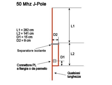 The J Pole antenna is a good omnidirectional antenna that can be used for portable or fixed station usage. It does not need a ground, and neither complex feed systems. It can be homemade with simple material and in several ways.Article in Italian
 -
 Efficient Low Band Counterpoise for Restricted Circumstances Loss Avoidance Opportunities and Techniques for the Low Bands The short and linear FCP was designed to reduce ground losses from inadequate radial systems beneath inverted L and other vertical antennas.
 -
 DF0WD/DL4YHF's Longwave Overview details amateur radio operations on the 135.7 to 137.8 kHz segment in Germany. The author outlines the "inofficial" European band plan, specifying segments for QRSS, TX tests, beacons, conventional CW, and data modes. Early LF activities at DF0WD began with a 20-watt CW transmitter, later upgraded to a homemade linear transverter capable of 100 watts, driven by an Icom IC706 on 10.137 MHz. The station's antenna system includes a 200-meter wire, approximately 10 meters above ground, supported by football field light-masts. Despite its length, the antenna's efficiency is noted as very low due to the immense wavelength of about 2.2 km. The author's experience highlights the significant challenge of achieving effective radiated power (EIRP) on LF, estimating DF0WD's EIRP at around 80 milliwatts based on field strength measurements from PA0SE. DF0WD/DL4YHF has successfully worked numerous countries on 136 kHz CW, including DL, F, G, GI, GM, GU, GW, HB9, HB0, LX, OE, OH, OK, OM, ON, OZ, PA, and SM. The author also mentions ongoing efforts to log contacts with CT, EI, LA/LG, and to complete a two-way QSO with Italy, demonstrating persistent activity on this challenging band.
 -
 Yamuna Cable Accessories Pvt. Ltd. specializes in the development, manufacturing, and marketing of power cable accessories, including a comprehensive range of cable jointing kits and components. The product line encompasses _Heat Shrink_ and _Cold Shrink_ cable joints, heat shrinkable tubing, pre-moulded slip-on joints, resin pour, and Tapex systems, all designed for applications up to 66 kV. The company highlights its ISO 9001-2015 certification, signifying adherence to international quality management standards in its manufacturing processes. The resource details specific product categories such as end caps, insulation piercing connectors, copper mesh, fireproof coatings, tubing and components, lugs and ferrules, and safety products. It also features specialized items like _Elbow Connectors_ rated for 25 kV-250, 400, and 630 amps, and various types of tinned copper braid used for grounding and electrical shielding. The site provides an overview of their manufacturing capabilities and global presence across 40+ countries. Established in 1973, Yamuna Densons has over four decades of experience in the industry, positioning itself as a significant designer, manufacturer, and supplier of insulators, tabs, and cable jointing systems in India. The company emphasizes its role as a leading exporter of these products, serving both domestic and international clients.
 -
 The antenna ground or earth system can be key to its operation whilst also being a key safety feature. This article is about grounding systems for antennas, covering different aspects of grounds made for antenna safety, or expressly for lightning or just to improve antenna performance, being ground an antenna component.
 -
 Discovering a solution for limited space, the inverted L HF antenna emerges as a stellar performer. Half the size of a dipole, it ensures optimal installation in restricted areas, maintaining superb transmission (TX) and reception (RX) characteristics. Spectrum Communications' multi-band version, featuring traps, proves even more space-friendly without compromising performance. A fiberglass pole offers sturdy support, while proper grounding, an RF choke, and occasional tuning contribute to a high-performing and reliable antenna system.
 -
 This article describes a simple yet effective multi-band vertical HF antenna design that performs exceptionally well across 80m to 10m bands. The antenna consists of a 13.4m wire mounted on a 12.4m Spiderpole, complemented by four 12m radials and a ground rod. Initially tuned with a manual LC circuit, it was later upgraded with a CG3000 remote auto ATU for convenient band switching. Despite antenna modeling software suggesting limited performance on higher frequencies, the system demonstrated excellent DX capabilities across all bands, outperforming more complex vertical antenna designs.
 -
 Integrating a **160-meter vertical wire antenna** with an existing 80-meter Yagi system presents unique challenges for Top Band operation. This project outlines the author's experiences with seasonal antenna removal and reinstallation, a necessary task for agricultural land use. It details specific issues encountered, such as incorrect coil sizing and relay configuration problems, providing practical insights into common pitfalls. The article describes the iterative tuning process, comparing **NEC model** predictions with actual on-air performance. It emphasizes the importance of precise measurements and adjustments to achieve optimal resonance and impedance matching. The author shares lessons learned from troubleshooting, including the impact of ground system integrity and feedline considerations. Concluding with an antenna checkup, the resource addresses long-term maintenance aspects, including galvanic corrosion prevention and general upkeep for reliable operation.
 -
 Steve Nichols, G0KYA, presents a practical examination of ground systems for vertical antennas, drawing heavily on the empirical research of Rudy Severns, N6LF. He explains that a robust radial field is crucial for ground-dependent verticals, effectively replacing the antenna's "missing half" and mitigating severe RF absorption in lossy soil. Nichols clarifies that surface radials do not strictly require a quarter-wavelength; instead, deploying a minimum of 16 to 32 shorter wires often yields superior results compared to fewer, longer ones. The presentation also addresses the common SWR paradox: a poor ground might show a perfect 1:1 match, but adding radials, while potentially raising the SWR to around 1.4:1, significantly improves true radiation efficiency. Nichols defines counterpoises as elevated wire networks that substitute for earth connections, offering solutions for limited-space installations, such as the **Folded Counterpoise (FCP)** for 160 meters. This resource provides actionable engineering data for optimizing vertical antenna performance.
 -
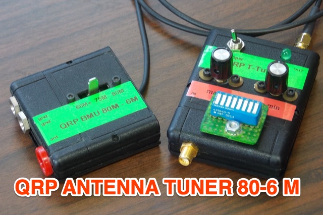 In the pursuit of an affordable matching and SWR indication solution for the Pixie-based transceiver system this T-Tuner and SWR bridge unit, while not groundbreaking, proves to be a cost-effective performer. With real-world impedance testing yielding a worst-case loss below 0.9 dB, the unit efficiently matches all bands on 80 M to 10 M ham bands, making it a valuable addition to the QRP system.
 -
 For amateur radio operators engaging in portable operations like SOTA or POTA, rapid deployment of an effective antenna system is paramount. This video resource details the assembly process for the Buddipole multiband dipole antenna, showcasing its components and how they fit together. Rob, VK5SW, systematically presents the mast, coil arms, radiating elements, and the VersaTee hub, emphasizing the modular design that allows for quick configuration changes across various HF bands. The demonstration highlights the antenna's adaptability for different operating environments, from a ground-mounted vertical to a horizontal dipole. The video illustrates the ease with which the antenna can be packed and deployed, making it a practical choice for activations where setup time is limited. The Buddipole's design facilitates efficient band changes and tuning, crucial for maximizing QSO opportunities during field operations.
 -
 VFC has grown to become the national leader in the lightning protection industry. Protecting facilities and equipment from lightning and transient current by designing and installing lightning protection, grounding, surge protection and lightning warning systems.
 -
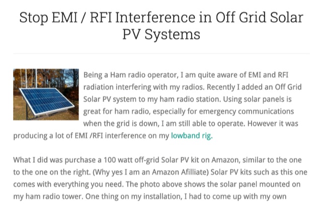 Stop EMI RFI Interference in Off Grid Solar PV Systems, in this article the author provides hints on tracking down the EMI or RFI source, shielding and grounding in order to eliminate interferences on the whole HF and VHF ham radio bands
 -
 WB5NHL describes setting up a 160-meter antenna on a small suburban lot, where standard options like Beverage antennas and 1/4 wavelength verticals require extensive space and ground systems. Instead, Guy Olinger's Folded Counterpoise (FCP) provides a solution. The FCP minimizes ground losses by using a folded wire design, allowing effective antenna placement in limited space. The FCP, fed with an isolation transformer, enabled WB5NHL's first 160-meter antenna installation, offering improved performance despite space constraints.
 -
 The Beverage on Ground (BOG) antenna offers ham radio operators a compact alternative to traditional Beverage antennas, requiring less space and fewer support structures. This implementation, optimized for 1.8-7 MHz bands, describes ideal parameters: lengths of 60-90 meters, height of 2-10 cm above ground, and specific load resistances based on configuration. The article details experimental methods for determining optimal load resistance and presents matching systems to convert BOG impedance to 50 ohms. While less effective than classic 200-300 meter Beverages, the BOG provides directional reception in limited space, though performance varies with ground conditions and weather changes.
 -
 This article presents a novel Top Loaded End-Fed Half-Wave (TLEFHW) antenna design for 20-meter ham radio operation. The antenna features a compact 14-foot vertical radiator with a capacitance hat configuration, eliminating the need for radials or ground systems. Using EZNEC modeling and field testing, the design achieves a 1.5:1 SWR across the 20m band with a 4.11 dBi gain. Key features include quick deployment, lightweight construction, and directional radiation pattern with 110-degree beamwidth. The design, while requiring a 45-foot footprint due to the top hat, offers an effective portable solution for amateur radio operators seeking a no-ground, no-tuner 20m antenna option.
 -
 Integrating a _Software Defined Radio_ (SDR) into an existing ham radio setup involves connecting it with a standard transceiver (TRX), power amplifier (PA), and antennas. The core component is a splitter box that facilitates the connection between the TRX and the SDR, allowing for simultaneous operation without modifying existing equipment. In receive mode, the splitter ties the antenna inputs of both the TRX and a direct conversion receiver (DC RX) together. During transmission, the DC RX input is grounded via a fast telecom relay controlled by the transceiver's -SEND signal, incorporating a 10ms delay for safety. The splitter box includes a 3.7 dB input attenuator for impedance matching and acts as a protective fuse for the DC RX input. Ground loops are mitigated using common mode balun transformers, while the DC RX input is insulated with a broadband transformer. An audio switch box complements the setup, enabling users to listen to either the main transceiver, the SDR output, or both simultaneously. This configuration ensures noise immunity and safety, with the splitter housed in a screened box made from PCB material. On-air tests, such as the CQ WW 160m CW DX Contest, demonstrate the system's effectiveness, showcasing the SDR's ability to handle crowded band conditions with superior selectivity and dynamic range. The SDR's narrow bandwidth filters and waterfall display provide significant advantages, allowing operators to detect weak signals amidst strong interference. The integration of SDR with conventional radios offers enhanced operational flexibility and performance in challenging environments.
 -
 Documents the operational planning for the **XX9W** DXpedition to Macao, a **DXCC** entity. This resource outlines the team composition, identifying 14 operators from various IARU regions, including EA1CJ, F2JD, and JH4RHF. It details the expedition's objective to activate Macao, officially the Macao Special Administrative Region of the People's Republic of China, emphasizing its distinct blend of Portuguese and Chinese cultures, historic architecture, and urban landscape. The site also provides information on how to support the DXpedition through donations, facilitating contributions via PayPal. Macao operates under the "one country, two systems" principle, with Chinese (Cantonese) and Portuguese as official languages, and a population exceeding 680,000. The content highlights the region's geographical location on the southern coast of China, across the Pearl River Delta from Hong Kong, and its historical background as a Portuguese colony.
 -
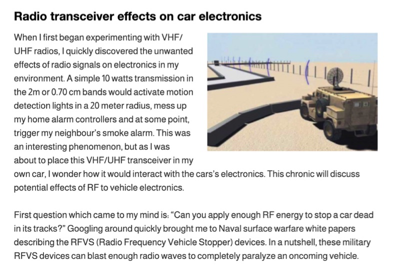 Illustrates the potential for radio frequency (RF) energy from amateur transceivers to interfere with vehicle electronics, drawing parallels to military _Radio Frequency Vehicle Stopper_ (RFVS) technology. The resource details personal experiences with VHF/UHF signals activating household devices and then pivots to the complexities of RF interaction with automotive systems, noting the development of multi-frequency RFVS (MFRFVS) to overcome vehicle-specific vulnerabilities. It highlights that while car manufacturers conduct RF immunity tests, the rigor varies, with luxury brands likely performing more extensive evaluations than others who merely meet minimal certification. The article explores practical considerations for mobile amateur radio installations, suggesting antenna placement over the car, using lower power output, and proper grounding to mitigate adverse effects. It acknowledges the lack of comprehensive data on RF/vehicle combinations but emphasizes that adherence to these basic principles can reduce risks. The author shares observations of unexplained car computer codes in a 2002 SUV, speculating on potential RF induction. Concerns are raised about the increasing complexity and interconnectedness of modern car electronics, including Bluetooth, remote access, and electronic control systems for critical functions like steering and braking. The article points out the diminishing space for third-party installations in contemporary vehicles and references the ARRL's stance on auto manufacturer policies regarding amateur radio installations, which generally advise against them.
 -
 Demonstrates the design and modeling of a **160m** vertical antenna, dubbed the "WindoVert," specifically for urban amateur radio operators with limited space. The resource covers the theoretical underpinnings of antenna height and radiation patterns, using EZNEC software to analyze current distribution and 3D radiation patterns for various configurations, including a Marconi-style "T" antenna. It details the integration of existing antenna components, such as a Carolina Windom balun and line isolator, into the new vertical setup, and the practical measurement of feedpoint impedance using an antenna analyzer. The article further explores the challenges of achieving low-angle radiation on Top Band, emphasizing the critical role of radial systems and mitigating ground loss. Author VE1ZAC presents EZNEC models illustrating the impact of lumped components and discusses the practical considerations of resonant frequency adjustment and impedance matching for **QRP** operation. The text details the calculation of required loading coil inductance and capacitance, and shares field results, including successful DX contacts on 160m and unexpected excellent performance on 30m.
 -
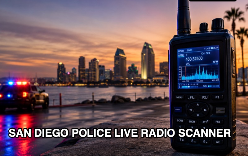 Monitoring public safety communications, particularly fire department dispatch, presents a unique challenge as agencies increasingly move towards encrypted systems. This Broadcastify feed, originating from a _BCD396XT_ scanner situated in northern San Diego City, provides real-time audio for the San Diego City Fire Department. While it previously included police dispatch, those transmissions are now fully encrypted, a common trend impacting scanner enthusiasts and emergency services observers alike. The setup utilizes a Windows server running _Freescan_ and _RemoteFS_ for remote control, ensuring consistent operation and clear audio via a ground loop isolator. With a peak of 8,785 listeners in the last 24 hours, the feed demonstrates significant interest in local emergency traffic. Alpha tags, indicating the current channel, are generally available for premium users, enhancing situational awareness for listeners. Feed archives are maintained in 30-minute segments, allowing for review of past incidents and operational patterns, a valuable feature for those studying emergency response or simply keeping informed about local events.