Search results
Query: low to ground antenna
Links: 76 | Categories: 0
-
 AN-SOF is a professional comprehensive software tool for the modeling and simulation of antenna systems. AS-SOF allows to describe antenna geometry, Choose construction materials, Describe the environment and ground conditions, Describe the antenna height above ground, Analize radiation pattern and front-to-back ratio, Plot directivity and gain, Analize input impedance and VSWR,Predict antenna bandwidth
 -
 On December 12, 1901, Guglielmo Marconi successfully received the first transatlantic wireless communication, a Morse code "S" (three dots), at 04:30 GMT. This article details the setup for this groundbreaking experiment, noting Marconi's receiver in St. John’s, Newfoundland, Canada, utilized a _coherer_ and an antenna elevated by balloons and kites. The transmitting station at Poldhu, Cornwall, England, featured twenty-four 200-foot ships' masts and a 25-kilowatt alternator. The resource explains how this contact disproved contemporary beliefs about radio wave limitations due to Earth's curvature, later understood through _ionospheric propagation_. It frames Marconi's achievement as the "very first DX" in amateur radio terms, defining DX as telegraphic shorthand for distance and _DXing_ as the hobby of receiving distant signals. The article also provides external links for further reading on Marconi's experiments and the science behind transatlantic radio signal reception.
 -
 Efficient Low Band Counterpoise for Restricted Circumstances Loss Avoidance Opportunities and Techniques for the Low Bands The short and linear FCP was designed to reduce ground losses from inadequate radial systems beneath inverted L and other vertical antennas.
 -
 This article presents an innovative homebrew antenna design utilizing surplus ladder line as a receiving antenna for HF and MF bands. The Ladder Line Antenna (LLA) transforms standard 450-ohm ladder line into a directional, bidirectional, or omnidirectional antenna system through different termination methods. The design, which requires minimal space and height, achieves 6-10dB front-to-back ratio on 40-160m bands using a 33-foot length. This DIY wire antenna project offers an efficient, low-profile solution for amateur radio operators, featuring broadband operation without ground radials and easy installation below fence height.
 -
 DF0WD/DL4YHF's Longwave Overview details amateur radio operations on the 135.7 to 137.8 kHz segment in Germany. The author outlines the "inofficial" European band plan, specifying segments for QRSS, TX tests, beacons, conventional CW, and data modes. Early LF activities at DF0WD began with a 20-watt CW transmitter, later upgraded to a homemade linear transverter capable of 100 watts, driven by an Icom IC706 on 10.137 MHz. The station's antenna system includes a 200-meter wire, approximately 10 meters above ground, supported by football field light-masts. Despite its length, the antenna's efficiency is noted as very low due to the immense wavelength of about 2.2 km. The author's experience highlights the significant challenge of achieving effective radiated power (EIRP) on LF, estimating DF0WD's EIRP at around 80 milliwatts based on field strength measurements from PA0SE. DF0WD/DL4YHF has successfully worked numerous countries on 136 kHz CW, including DL, F, G, GI, GM, GU, GW, HB9, HB0, LX, OE, OH, OK, OM, ON, OZ, PA, and SM. The author also mentions ongoing efforts to log contacts with CT, EI, LA/LG, and to complete a two-way QSO with Italy, demonstrating persistent activity on this challenging band.
 -
 The Linked Dipole is a multiband antenna designed for 80/60/40/30/20m bands, optimized for the (tr)uSDX low bands configuration. It incorporates a 1:1 Balun to prevent common mode currents, ensuring balanced operation with coaxial cable. The Balun, wound on an FT140-43 core, achieves 37-40dB attenuation. The design includes a 3D-printable housing for compactness and waterproofing, with labeled link insulators for ease of use. Wire lengths were meticulously adjusted for optimal performance with a 7m pole and 3m rope extension, ensuring the antenna's ends are off the ground for improved behavior. The project includes downloadable printables for DIY construction.
 -
 Author found a ratio between the lengths of the sides of the Delta Loop that give reasonably low SWR into a 50 ohm coaxial cable almost independent of the high above ground and other surroundings. This ratio also gives good results no matter orientation. Includes an online delta loop antenna calculator.
 -
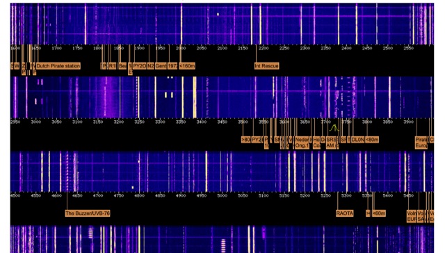 RSP1A receiver with LoG (Loop On Ground) antenna in quiet QTH - southeastern Poland. Very low QRM!
 -
 The _G3TSO_ Mobile Antenna Page details construction and tuning methods for mobile antennas operating across **10 to 160 metres**. The content describes a Hustler-based design, optimized for RF performance and vehicle speeds, featuring centre loading. For optimal operation on various bands, the loading coil placement requires clearance from the vehicle body. Antenna resonance is critical for efficient mobile operation. A mobile antenna's base impedance may be as low as 27 ohms, requiring specific matching to achieve maximum radiation, as a minimum SWR at the transmitter does not always indicate resonance or maximum output. Tuning involves physical adjustment of antenna length to achieve resonance at the operating frequency. The _G3TSO_ page outlines a tuning procedure utilizing a low-power signal source and a field strength meter to identify maximum radiation before impedance matching. Loading coil placement, either at the base, center, or top of the antenna, influences radiation efficiency and mechanical stability for mobile installations. Centre-loaded whips, such as the Hustler design, offer a compromise between efficiency and stability, often for single-band operation. Helically wound antennas, including those for **28 MHz**, may present base impedances around 17 ohms, resulting in a 3:1 SWR at resonance. Low resistance grounding at the antenna base is also specified for optimizing performance and minimizing RFI during mobile operation. DXZone Focus: Mobile | Any | Antenna Tuning | HF
 -
 The 80-meter Skyloop antenna, a top-performing HF antenna, excels in weak signal work, low-noise operation, and omnidirectional coverage. Ideal for fixed stations, it delivers strong performance at low power, outperforming many alternatives, including 80m half-wave end-fed antennas. Requiring significant space for deployment, it’s well-suited for NVIS and groundwave use. Though not portable, it’s cost-effective and durable, with minor maintenance needs. Tuning may require adjustments for optimal resonance. It’s a standout for base stations, though a lighter portable version could enhance its versatility.
 -
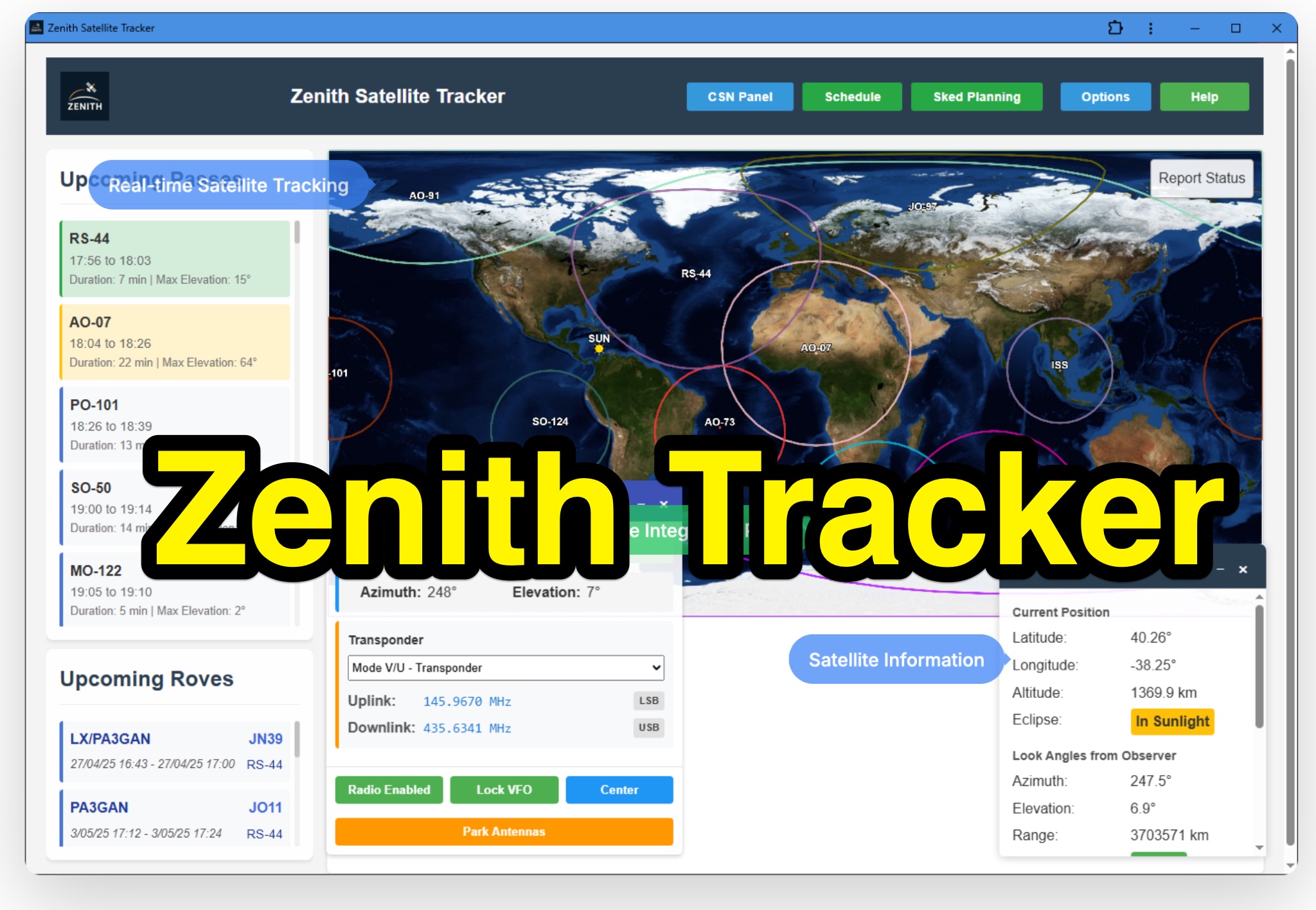 Zenith Tracker offers real-time satellite tracking, pass predictions, and radio hardware integration for ham radio operators. The platform includes an interactive world map showing satellite positions, footprints, and ground tracks, as well as a polar radar visualization for detailed pass analysis. Users can view upcoming passes, set filters, and receive notifications. Integration with CSN Technologies S.A.T Hardware and QTRigDoppler allows for automatic radio control, antenna tracking, and transponder management. The platform also offers APRS message interface, grid square-based location input, and API integration for rover activations. Zenith Tracker is recommended for both general users and those needing advanced hardware integration.
 -
 Operating from Banana Island, Sierra Leone (AF-037), the 9L2019 DXpedition by F6KOP and a ten-operator team used the callsign 9LY1JM from January 9-21, 2019. This detailed report covers the logistical challenges, including securing visas and licenses with local assistance from Mark 9L1YXJ and Gregory of Dalton’s Guest House. The team deployed monoband quarter-wave verticals on the beach and two Beverage on Ground (BOG) antennas for Europe/Asia and the USA, operating four stations simultaneously. Technical hurdles encountered included high tides submerging antennas, requiring repositioning, and persistent QRM between closely spaced stations, mitigated by doubling filters. CW signal irregularities at 30-32 WPM were resolved by PC and WINTEST restarts. A significant FT8 logging bug was identified and corrected with on-site software. Despite these issues, the team logged over 4,000 QSOs in the first 24 hours, averaging 5,000 QSOs daily, with a peak of over 6,000 in one day. Propagation varied, with excellent 160m conditions on January 12 yielding over 750 QSOs, and a later four-hour opening pushing the 160m total past 1,600. High bands were challenging due to low solar activity, but mid-bands provided intense pileups and rapid continent-wide contacts. The DXpedition concluded with nearly 50,000 QSOs, including a successful school QSO with Collège Doisneau de Sarralbe (57), managed by F1ULQ and F6KFT.
 -
 For amateur radio operators engaging in portable operations like SOTA or POTA, rapid deployment of an effective antenna system is paramount. This video resource details the assembly process for the Buddipole multiband dipole antenna, showcasing its components and how they fit together. Rob, VK5SW, systematically presents the mast, coil arms, radiating elements, and the VersaTee hub, emphasizing the modular design that allows for quick configuration changes across various HF bands. The demonstration highlights the antenna's adaptability for different operating environments, from a ground-mounted vertical to a horizontal dipole. The video illustrates the ease with which the antenna can be packed and deployed, making it a practical choice for activations where setup time is limited. The Buddipole's design facilitates efficient band changes and tuning, crucial for maximizing QSO opportunities during field operations.
 -
 This page provides information on designing a lightweight Moxon antenna for the upper HF bands and VHF. The Moxon antenna is a compact version of a 2-element Yagi with folded elements, offering good forward gain and a high front-to-back ratio. It is designed for a single band with a feed-point impedance close to 50 ohms. Hams can orient the antenna horizontally or vertically, with polarization following the configuration, affecting radiation patterns. The page allows users to generate radiation pattern plots, VSWR charts, antenna currents diagrams, and Smith charts for their antennas on different ground types, helping them understand antenna performance in the field.
 -
 This page allows hams to design a vertical-plane delta-loop antenna for a single amateur HF band in different configurations. By choosing different feed-point positions, operators can observe variations in polarization properties, radiation patterns, and feed-point impedances. Users can generate radiation pattern plots, VSWR charts, antenna current diagrams, and Smith charts for their antennas over various ground types. Through adjusting the antenna's physical dimensions and refreshing the plots, hams can gain insights into the antenna's performance in the field. The page also discusses how elevation radiation patterns may change based on the antenna configuration and feed-point position.
 -
 This page provides information about building a Beverage antenna for hams. The article discusses using a 60m wire on the ground to create an effective antenna for amateur radio operators. Learn how to set up and optimize this type of antenna for better reception and communication. This describes a low-noise receiving Beverage antenna setup for low bands, using a N30 cup core transformer for 1:4 impedance matching (likely 50:200 Ohm), RG-58 feedline with heavy common-mode choking, and conduit for wire burial.
 -
 A C-Pole Antenna for QRPxpeditions describes a DIY C-Pole antenna designed for QRP (low-power) expeditions, inspired by KF2YN’s ground-independent vertical model. After adjustments, it achieved a 1:1 SWR at 14.060 MHz, rising to 2.5:1 at 14.35 MHz. A choke balun, comprising 15 turns of RG8X around a 4†can, was essential for optimal performance. Compact and self-supporting, the antenna enables reliable communication with minimal setup. Contacts included stations across the U.S., and even a 4,600-mile connection to Spain using only 5 watts.
 -
 WB5NHL describes setting up a 160-meter antenna on a small suburban lot, where standard options like Beverage antennas and 1/4 wavelength verticals require extensive space and ground systems. Instead, Guy Olinger's Folded Counterpoise (FCP) provides a solution. The FCP minimizes ground losses by using a folded wire design, allowing effective antenna placement in limited space. The FCP, fed with an isolation transformer, enabled WB5NHL's first 160-meter antenna installation, offering improved performance despite space constraints.
 -
 Learn how to construct a balanced Antenna Tuning Unit (ATU) for your ham radio equipment. Follow the instructions provided by Bengt, SM6APQ, to create a variable capacitor insulated from the ground for additional safety. Discover how to set up the ATU for the 20 to 10m band with proper spacing between coils. Use low power when adjusting the ATU for lowest SWR. Avoid using switches and opt for banana plugs for flexible connections. Visit the Creative Science Centre website for more information and resources on ATU construction.
 -
 Integrating a _Software Defined Radio_ (SDR) into an existing ham radio setup involves connecting it with a standard transceiver (TRX), power amplifier (PA), and antennas. The core component is a splitter box that facilitates the connection between the TRX and the SDR, allowing for simultaneous operation without modifying existing equipment. In receive mode, the splitter ties the antenna inputs of both the TRX and a direct conversion receiver (DC RX) together. During transmission, the DC RX input is grounded via a fast telecom relay controlled by the transceiver's -SEND signal, incorporating a 10ms delay for safety. The splitter box includes a 3.7 dB input attenuator for impedance matching and acts as a protective fuse for the DC RX input. Ground loops are mitigated using common mode balun transformers, while the DC RX input is insulated with a broadband transformer. An audio switch box complements the setup, enabling users to listen to either the main transceiver, the SDR output, or both simultaneously. This configuration ensures noise immunity and safety, with the splitter housed in a screened box made from PCB material. On-air tests, such as the CQ WW 160m CW DX Contest, demonstrate the system's effectiveness, showcasing the SDR's ability to handle crowded band conditions with superior selectivity and dynamic range. The SDR's narrow bandwidth filters and waterfall display provide significant advantages, allowing operators to detect weak signals amidst strong interference. The integration of SDR with conventional radios offers enhanced operational flexibility and performance in challenging environments.
 -
 Delta loop antennas, particularly the 30 meter variant, offer unique advantages in terms of vertical polarization and omni-directional coverage. The construction process detailed by VE3VN highlights common mechanical and electrical challenges faced by amateur radio operators. Key design considerations include minimizing interaction with existing contest band antennas, achieving low elevation angles for DX chasing, and ensuring the antenna remains off the ground for agricultural clearance. The article provides specific measurements, such as the loop's height and feed point impedance, which are critical for optimizing performance. The use of NEC modeling software illustrates the importance of accurate resonance calculations, revealing how proximity to the tower affects both pattern and impedance. This practical account serves as a resource for hams looking to build effective antennas while navigating typical construction hurdles.
 -
 This is a theoretical look at propagation on 630-Meters and 2200-Meters using ray tracing software. It expands on the brief discussion in the ARRL Handbooks. The Earth's magnetic field affects 630-Meter and 2200-Meter band propagation. Lower ionization reduces absorption, aiding low-frequency propagation. Differences exist between bands, limited daytime sky-wave propagation. Sunrise/sunset show promise, yet mechanisms are unclear. Ducting possible at night in specific conditions. Negative ions enhance propagation. Inefficient antennas and high man-made noise are anticipated. Groundwave propagation is significant on 2200-Meters.
 -
 This article explores Beverage antennas, a type used for low-frequency radio reception. Despite the mystique, they are relatively simple wire antennas placed near the ground. Their key benefit is improved signal-to-noise ratio by rejecting unwanted signals. While lengthier antennas offer better reception, even shorter versions (around 200 feet) can improve DX reception compared to traditional antennas.
 -
 Operating amateur radio satellites presents unique challenges, particularly concerning antenna design and signal propagation. Juan Antonio Fernández Montaña, EA4CYQ, recounts his three-year journey into satellite communication, starting with initial guidance from EB4DKA. His early experiments involved a portable 1/4 wave VHF antenna with four 1/4 wave ground planes, designed for hand-held use to adjust polarity. This setup, paired with an FT-3000M transceiver, allowed full-duplex operation on **VHF** transmit and **UHF** receive, proving effective for early contacts on satellites like AO27, UO14, and SO35. EA4CYQ's experience highlights the critical role of coaxial cable loss and antenna polarization. After encountering significant signal degradation with longer RG213 runs, he experimented with a 1/2 inch commercial cable, noting improved reception but persistent fading due to varying satellite polarities. This led to the construction of an **Eggbeater II** antenna, an omnidirectional UHF design offering horizontal polarization at the horizon and circular right polarization at higher elevation angles. Subsequent modifications resulted in the directional **TPM2** antenna, which provided sufficient gain for LEO satellites with a wide 30-degree lobe, enabling consistent contacts from his home station. The article concludes with practical insights on the performance of the Eggbeater II for both UHF and VHF, and the TPM2 for UHF, emphasizing their utility for portable and fixed operations. EA4CYQ's journey underscores the iterative process of antenna development and the importance of adapting designs to overcome real-world propagation challenges in satellite communications.
 -
 The Gemini Amplifier Remote Control software operates on Windows 7 and above, facilitating remote management of the Gemini HF-1K and DX-1200 amplifiers. Users connect via Ethernet, configuring the amplifier's IP address through the front panel. The software allows seamless band and antenna selection, saving settings for each band without requiring transmission. Integration with _OmniRig_ from Afreet Software, Inc. enables automatic band adjustments based on the radio's frequency changes. Users can configure serial or virtual serial connections, with tracking options accessible through the ribbon bar. The software supports speech functionality, enhancing accessibility for operators. Firmware updates, such as version 2.5Ee, introduce features like background datalogging and power output control, uploaded via FTP. Version 1.2.0 allows users to offload internal parameter data for support purposes. The firmware upload process requires the amplifier's IP address and port 21, taking approximately 90 seconds. Users are encouraged to upgrade to the latest firmware for improved performance and remote diagnostics.
 -
 The 4m Slim Jim antenna project provides a construction guide for a low-cost, high-performance aerial designed specifically for the 70 MHz FM band. This design achieves a 1:1 SWR across the 4m FM band with straightforward adjustment of the feed point, utilizing RG-58 coax. Its low angle of radiation contributes to effective signal propagation. Construction involves using plastic knitting needles as spreaders and a telescopic fishing pole for support, with components secured using two-part epoxy. Annealed bare single-core copper wire forms the radiating element. The setup process includes raising the antenna at least 3 meters above ground for tuning, adjusting the RG-58 feed point for optimal SWR, and then soldering connections. Waterproofing is achieved with yacht varnish. The design emphasizes low wind resistance for durability, making it suitable for exposed outdoor installations. A PDF construction diagram is available to supplement the written instructions.