Search results
Query: pic s meter
Links: 131 | Categories: 0
-
 This note looks at the antenna and antenna model for the 40 meter Moxon Yagi designed by Dave Leeson, W6NL. The performance of the antenna, through the model, will be explored in several typical settings.
 -
 An homebrew crossed Yagi antenna for two meters band based on DK72B design with pictures, detailed description and tricks by Barry Zarucki M0DGQ
 -
 A six meter Moxon rectangle antenna. Includes high definition pictures and a detailed drawing by KG4JJH
 -
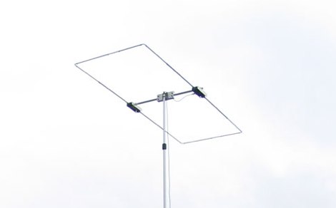
 A delta loop antenna for 6 meters band with SWR diagram , construction plan and some pictures by IZ8EWD in Italian
 -
 This vertical antenna consist of a 18 meters telescopic pole and allow operations from 160 to 30 meters band, project by Daniel Zimmerman N3OX
 -
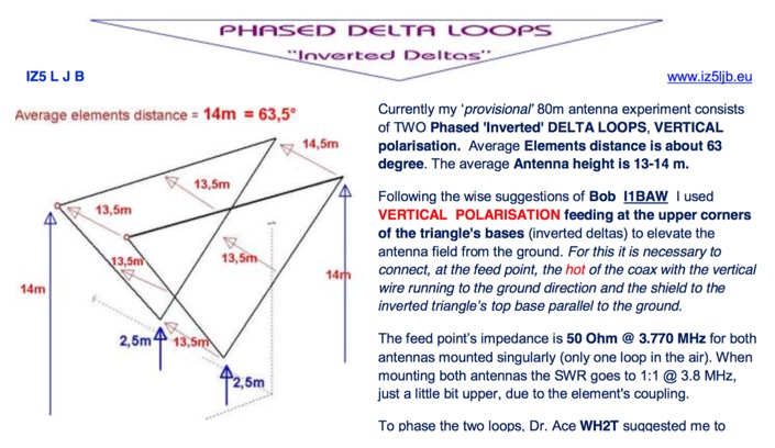 An interesting article with many technical details on a phased delta loop array for 80 meters band includes pictures of antenna relays
 -
 This page will help you answer important questions about antenna selection before you talk to a supplier. After reading this paper, you should be able to better determine the most important parameters you need to know for your antenna selection criteria.
 -
 The 11-meter band, often associated with Citizens Band (CB) radio, presents unique challenges and opportunities for long-distance communication, particularly for operators interested in DXing. This group facilitates discussions and information exchange among enthusiasts who operate on this frequency, often utilizing single-sideband (SSB) modulation for improved range and signal clarity compared to traditional AM CB operations. The community provides a platform for members to share experiences, technical insights, and propagation reports relevant to 27 MHz operations. Members engage in discussions covering various aspects of 11-meter DX, including antenna configurations, transceiver modifications, and operating techniques to maximize signal propagation across continents. The forum serves as a central hub for coordinating contacts, sharing QSL information, and celebrating successful long-haul QSOs. Specific topics often include optimizing power output, reducing noise, and understanding solar cycle effects on 27 MHz. The group's activities extend to organizing virtual gatherings and promoting ethical operating practices within the 11-meter DX community. It supports both seasoned operators and those new to the band, fostering a collaborative environment for exploring the capabilities of CB radio beyond local communications.
 -
 The Japanese Amateur Radio Teleprinter Society (JARTS) serves as a central hub for RTTY and PSK31 enthusiasts in Japan, providing essential information regarding its annual JARTS RTTY Contest. The resource outlines contest rules, exchange parameters, and scoring specifics, enabling participants to prepare effectively for the event. It also offers insights into the club's broader activities and its role in promoting digital mode operations within the amateur radio community. The site details the contest's operational periods and categories, which typically include single-operator, multi-operator, and SWL entries, often with power output classifications. Participants can find guidelines for log submission and result publication, ensuring adherence to the contest's administrative requirements. The JARTS RTTY Contest is a significant event for digital mode operators, drawing participation from across Asia and beyond. Beyond contest specifics, the resource provides historical context for JARTS, highlighting its foundational role in Japanese amateur radio digital communications. It serves as a primary point of contact for members and prospective participants, fostering engagement in RTTY and PSK31 modes.
 -
 GW4ALG's _136 kHz Pages_ document the evolution of vertical antennas for the 2200m band, starting with a prototype mounted on a house wall. This initial design, despite achieving the first **395 km** GM-GW QSO, suffered from significant insulation breakdown, high RF losses due to proximity to the house, and difficult tuning adjustments. The author details the challenges of maintaining resonance and matching with a variometer in the loft, noting that adding three earth spikes offered no measurable improvement over a simple water tap connection. The subsequent experimental 12m vertical, relocated away from the house, significantly reduced dielectric losses and proved far more effective. This antenna enabled GW4ALG to set a world DX record on 136 kHz with a **1916 km** QSO to OH1TN, and an intra-UK record of **703 km** to GM3YXM/P. The resource further explores the use of helium-filled balloons to extend the vertical radiator, achieving heights up to 27m, typically 20m, for enhanced low-band performance. Practical advice on balloon types, inflation, and critical insulation between the wire and balloon is provided, emphasizing safety and avoiding arcing.
 -
 A 500-watt mobile antenna project details the conversion of an old 10m hamstick into a highly efficient, multiband "bugstick" for HF operation. The core modification involves replacing the original coil with 25 turns of 6 turns-per-inch, 1.5-inch diameter coil stock, fabricated from #14 wire. This design, intended for a 3-magnet mount on a vehicle cab, achieves resonance on multiple bands by shorting out specific turns on the coil, similar to a **bugcatcher** antenna. Measurements taken with an MFJ-259 analyzer on a GMC pickup show 0 turns shorted for 20 meters (14.2 MHz), 10 turns for 17 meters, 16 turns for 15 meters, 19 turns for 12 meters, and 23 turns for 10 meters. The construction emphasizes using UV-resistant tie-wraps and #14 solid wire with crimp lugs for robust RF connections, bypassing the fiberglass rod for current flow. A bonus section details a 40-meter version, utilizing 48 turns of 8 TPI, 2-inch diameter coil stock.
 -
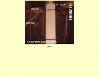 picture and dimensions of a coax loop antenna centered at 51.490 MHz
 -
 An end-fed halfwave antenna for 20 meters band with balun pictures and description by PD7MAA
 -
 Presents the DBO274 Citizen Band mailbox, a digital communication hub accessible via HTTP and Telnet, specifically catering to **CB radio** enthusiasts in Germany. This resource outlines its functionality for Packet and other digital emissions on the 11-meter band, a segment often overlooked by traditional amateur radio operators but vital for CB users seeking advanced communication methods. The author, DH8YMB, provides insights into its operation, reflecting practical experience with digital modes in the CB spectrum. The DBO274 serves as a bridge, enabling users to exchange messages and data packets, extending the reach and utility of standard CB transceivers. It represents a localized digital infrastructure, demonstrating how the 27 MHz band can support more than just voice contacts, incorporating elements of early internet-like communication within the CB community. This setup highlights the enduring innovation within the CB realm, adapting technologies like Packet Radio for a different user base. It underscores the versatility of radio communication, even on less conventional bands, for those interested in digital data exchange beyond the typical amateur allocations.
 -
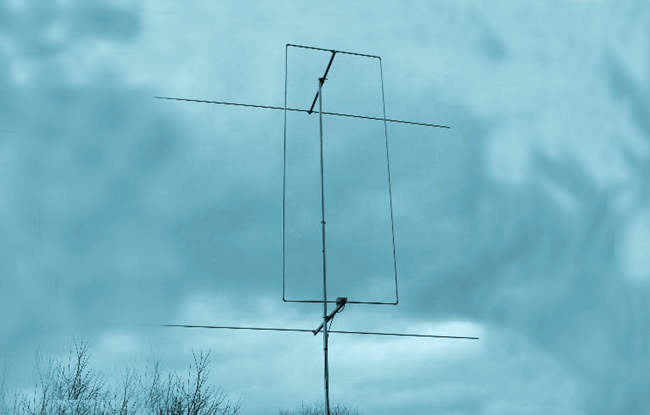 The Quadlong antenna for the six meter band. This antenna feature a total gain of 6,4 dBd, F/B 21 dB and is also available in 70MHz version. Includes detailed pictures and plot diagrams.
 -
 A Loop Fed Array Yagi antenna for 50 MHz featuring 11 dBi gain and 23 f/b ratio. In this excellent page the author even includes a detailed drawing in DWG format, with element lenght and spacing measures, in a separa file a full list of material list needed to build this yagi antenna including source and price, the EZnec file for this antenna plan, and a lot of pictures of this LFA Yagi for 50 Mhz. A ten page PDF file containing all infos, is also available to download.
 -
 For amateur radio operators engaged in **radio direction finding** (RDF) and **transmitter hunting** (T-hunting) activities, this resource provides a catalog of printed circuit boards (PCBs) for constructing various DF and foxhunt-related projects. The offerings include PCBs for 80-meter fox transmitters and receivers, UHF fox transmitters with audio recording capabilities, and several designs for general-purpose radio direction finders. Specific projects like the "Simple 80M ATX-80 Transmitter" and the "N0GSG DSP Radio Direction Finder" are listed, along with attenuator boxes and specialized components for Doppler DF systems. The catalog details PCBs for projects published in prominent amateur radio magazines such as *73's*, *CQ*, *QST*, and *PE*, indicating their origin and design pedigree. For instance, the "Montreal Fox Controller" is sourced from the *Homing-In* column by Joe Moell, K0OV. The resource also lists components for advanced Doppler DF systems, including main boards, LED display boards, and antenna switch boards, with options for programmed PIC microcontrollers. Pricing for each PCB is provided, allowing hams to acquire the necessary components for their DIY RDF endeavors.
 -
 The resource presents a detailed schematic for constructing a dual-band vertical antenna, specifically designed for operation on the 2-meter and 70-centimeter amateur radio bands. It illustrates the physical layout, critical dimensions, and component placement necessary for successful replication. Key elements such as the radiating elements, phasing sections, and feed point are clearly depicted, providing a visual guide for radio amateurs undertaking a homebrew antenna project. The diagram specifies the lengths for the VHF and UHF sections, indicating how these elements are integrated to achieve dual-band functionality from a single coaxial feedline. It also implies the use of common materials readily available to most experimenters, focusing on simplicity and effectiveness in its design. The visual format of a GIF image ensures direct access to the construction details without requiring extensive textual interpretation. This schematic serves as a practical reference for hams interested in building a compact, efficient vertical antenna for local and regional FM communications, offering a proven design for immediate implementation.
 -
 A fractional bandwidth of up to 30:1 characterizes spiral antennas, making them highly effective across a very wide frequency range, often from 1 GHz to 30 GHz. The resource details two primary types: the **Log-Periodic Spiral Antenna** and the **Archimedean Spiral Antenna**, defining each with specific polar functions and illustrating their planar configurations. It explains that spiral antennas are typically circularly polarized, with a Half-Power Beamwidth (HPBW) of approximately 70-90 degrees, and a peak radiation direction perpendicular to the spiral plane. The content elaborates on critical design parameters affecting radiation, including the total length (outer radius) for lowest frequency, the flare rate ('a' constant) for optimal radiation versus capacitive behavior, the feed structure (often an infinite balun) for high-frequency operation, and the number of turns (typically 1.5 to 3 turns). It also discusses the theoretical impedance of 188 Ohms for Log-Periodic spirals, derived from Babinet's Principle, noting actual impedances are often 100-150 Ohms. The article presents a simple construction method for an Archimedean spiral, demonstrating VSWR and efficiency measurements. Measurements from a constructed spiral antenna show a VSWR that is fairly constant across the band, albeit with a mismatch loss of about 3 dB. The antenna efficiency remains around -5 dB (31.6%) across its operating range, indicating a decent wideband radiator despite opportunities for optimization.
 -
 Showcasing a specialized product line, Advanced Receiver Research presents a comprehensive catalog of **low noise preamplifiers** and microwave **Gunnplexers**. The offerings span a broad spectrum of radio frequencies, from VLF, LF, MF, and HF bands up through VHF, UHF, and microwave, catering to diverse applications including amateur radio, commercial installations, and military systems. Their product range includes mast-mount preamplifiers, inline attenuators, power dividers, and various coaxial components. My own experience with similar low-noise front ends for weak-signal work on 2 meters and 70 centimeters underscores the critical role such components play in maximizing receiver sensitivity, especially when chasing distant DX or engaging in EME. The detailed product descriptions and technical specifications provided on the site allow operators to select the optimal preamplifier for their specific band and noise figure requirements, essential for improving signal-to-noise ratio. The site also lists specialized products for unique applications like Nuclear Magnetic Resonance (NMR) and Studio Transmitter Links (STL), demonstrating a depth of engineering capability beyond typical amateur radio fare. This breadth of offerings, coupled with clear ordering and warranty information, positions Advanced Receiver Research as a key supplier for high-performance RF components.
 -
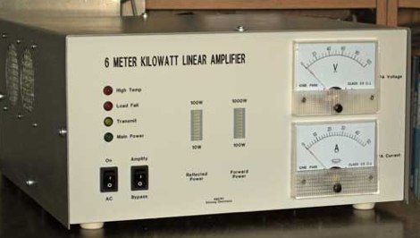
 This article loaded with nice pictures and schematics, describes a 160-10 meter linear amplifier that uses a pair of 3-500Z triode power tubes. It was designed and constructed by William Moneysmith, W4NFR. The amplifier features fast warm up and 1500-Watt RF output with 100-Watts of drive.
 -
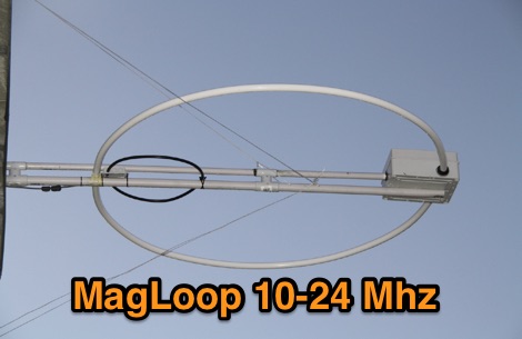
 The performance of a small magnetic loop can be improved constructing it larger, thicker or both. The antenna is covering from 12 Megahertz to 32 megahertz and adding a 156 Pico farads ceramic capacitor it resonates on the 40 meters band. by PY1AHD
 -
 6 Meter 1/4 Wave Antenna by Mike Fedler N6TWW. A detailed article with pictures of construction details of this 50 Mhz antenna
 -
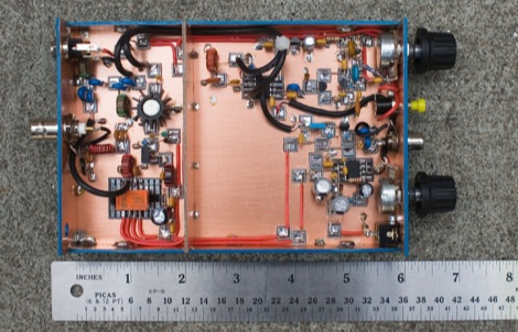 A hombrew QRP transceiver for 40 meter band with many pictures, circuit and sound recording of some QSOs made with this Rig consisting of 5 transistor and one chip.
 -
 Demonstrates various practical amateur radio projects and technical discussions through video episodes. One episode details cutting and retuning a _1/4 wave shorted stub_ from 101.7 MHz to 107.5 MHz to safeguard a transmitter's driver stage, alongside insights into advanced _160-meter antenna systems_ like eight-circle arrays and beverage antennas. Another segment covers upgrading firmware on an _ATS-20+_ receiver using AverDudes for improved display and functionality, and a detailed guide on using D-Star DR mode on an _ICOM ID-52A_ for international repeater programming. Additional content includes a deep dive into _OpenHamClock_ as a potential replacement for the HamClock project, updates on _Raspberry Pi 5_ running Trixie OS, and a review of the Choyong LC90 Internet radio with AI integration. The series also features "Ham College" episodes, which meticulously prepare viewers for the Technician Exam by covering topics such as antenna and transmission line measurements, SWR interpretation, and the functions of basic electronic components like rectifiers, relays, and transistors. Practical advice on coaxial cable characteristics, dummy loads, and proper soldering techniques is also provided.
 -
 A 2 element 40 meters band parasitic delta loop antenna project with pictures and details
 -
 Antenna tuners are crucial for matching the impedance of antennas to the 50 ohm output impedance of transmitters. The _LDG Z-11 Pro_ is an automatic antenna tuner designed to handle up to 125 watts, making it suitable for a wide range of amateur radio applications. Its compact form factor allows it to pair well with transceivers like the _FT-857D_, providing a portable solution for operators who frequently change locations or setups. The tuner covers the 80 through 6 meter bands, offering a broad impedance match capability. Although it struggles with some loads, it performs well with typical ham antennas, even managing to load an 80 meter dipole on 6 meters. One of the standout features of the _Z-11 Pro_ is its 8000 memory slots, which enable it to remember successful matches and quickly retune when revisiting frequencies. This memory function significantly reduces tuning time, often to less than half a second. The unit is well-constructed, with improved pushbuttons and a sturdy metal case that offers good shielding. However, users should be aware of potential RFI issues and the lack of a power switch, which requires disconnecting the power cord to turn off the unit completely. Overall, the _LDG Z-11 Pro_ is a user-friendly and cost-effective tuner, offering advanced features that enhance its utility in various amateur radio setups.
 -
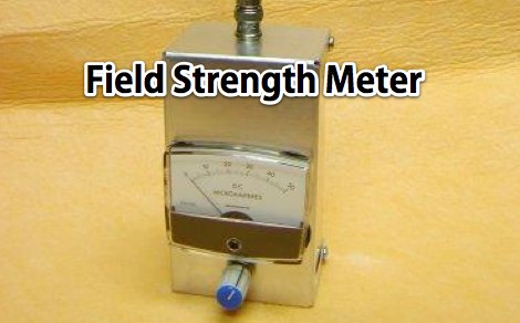 A home made field strength meter wit detailed pictures and schematic diagram by W4ZT
 -
 This resource provides a unique historical audio archive of 50 MHz DX contacts, documenting significant F2 and Es propagation events experienced by PA2S (formerly PA2HJS) since 1978. The collection includes recordings of beacons and two-way QSOs with stations across North America, South America, Asia, Australia, Europe, and Africa. Specific entries detail contacts with rare DX entities such as ZS6PW, VE1AVX, C5AEH, J52US, TR8CA, LU8MBL, VK8ZLX, and various Japanese stations, often noting the mode (SSB or CW) and propagation type. The archive also highlights challenging pile-up situations and frustrating near-misses during major openings. The recordings, initially in RealAudio format for solar cycles 21 and 22 and later in MP3 for cycle 23, offer a practical illustration of 6-meter band conditions over several solar cycles. The content allows hams to listen to actual signals from different continents, observing signal characteristics like typical TEP fading from 5H3RA or strong F2 backscatter from OZ1BVW. It provides a comparative perspective on propagation effectiveness between solar cycles, noting that cycle 23, while not as robust as previous cycles, still yielded interesting openings. The archive serves as a valuable educational tool for understanding real-world 50 MHz DXing and propagation phenomena.
 -
 An homebrew project of a full wave delta loop antenna for the 40 meters band with dimensione, picture and assembling instructions in Indonesian
 -
 The NB6Zep Antenna, an electrically shortened 80-meter end-fed wire, addresses space constraints for low-band operation by integrating two loading coils into a 37-foot wire. This design, modeled with _EZNEC_, explores configurations like the quarter-wave sloper and inverted-L, with the latter providing a more vertical radiation pattern and practical backyard deployment. The resource details specific coil construction, recommending 21 uH coils made from _BW coil stock #3026_ or similar, and outlines wire segment lengths for optimal tuning. Performance analysis indicates a radiating efficiency of approximately 27% with good ground conductivity, resulting in a signal typically 3-4 dB down compared to a full-size quarter-wave vertical. The antenna exhibits a narrow bandwidth, around 50 kHz, due to its high Q, necessitating a tuner for broader band operation. Feedpoint impedance is low, with ground resistance playing a critical role in achieving a usable SWR. The article emphasizes the importance of an effective ground rod at the feedpoint for proper operation and tuning, suggesting an antenna analyzer for precise adjustments. It confirms the antenna's suitability for DX, citing successful contacts from Oregon to the East Coast and Hawaii on a 160-meter variant, making it a viable option for urban operators seeking low-angle radiation on 80 meters.
 -
 WeatherExperts.Com, the premier online store for weather stations, instruments, anemometers, barometers, accesories, and satellite pictures. Excellent prices!
 -
 Demonstrating the construction of a short dipole antenna tailored for the 60 meter band, this resource provides detailed instructions for radio enthusiasts with limited space. The design incorporates inductive loading using two inductors (L1/L2) made from PVC tubes, allowing for effective operation on 5 MHz. The antenna consists of 12 meters of wire, divided into four sections, with specific dimensions and materials outlined for optimal performance. Results from users indicate that this antenna can significantly enhance DXing capabilities on the 60 meter band. Feedback from operators suggests that while the design is effective, adjustments may be necessary based on individual setups, such as coil diameter and wire gauge. Many users report successful construction and operation, with some experimenting with variations to improve resonance. The practical application of this antenna design has led to successful contacts and improved signal quality, making it a popular choice among 60 meter band operators.
 -
 The **Solarcon A99** vertical antenna, a half-wave over a quarter-wave variable mutual inductance design, primarily serves the 11-meter CB band but also finds use on 10 and 12 meters for amateur radio operators. Its simple construction, consisting of three fiberglass sections and a 16 AWG radiating element, makes it an accessible option for new operators or those seeking an easy-to-install base station antenna without complex mounting requirements. Despite claims of 9.9 dBi gain being widely considered exaggerated, and a manufacturer rating of 2000 watts power handling often viewed with skepticism (with 300 watts suggested as a practical limit), the A99 maintains popularity due to its low cost and ease of deployment. It typically tunes to a 1.2-1.3 SWR out of the box, requiring minimal adjustment via its two tuning rings. Its high angle of radiation allows for effective local communication even when mounted at low heights, such as 8-10 feet off the ground. However, the A99 is known for significant RF bleed-over issues, particularly when operated with higher power or mounted close to residential electronics. While its internal design is often described as cheap, the antenna exhibits remarkable durability, frequently lasting a decade or more in various weather conditions. Its affordability and straightforward setup continue to make it a go-to choice for many radio enthusiasts.
 -
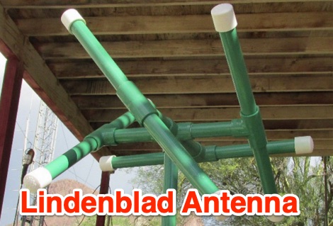 This is a presentation used at OVARC on the LindenBlad antenna construction. The presentation cover several topics about this antenna, from the basic antenna design, to the guide on how to contruct a custom lindenblad antenna for the 2 meters band and and 70 centimenters band.
 -
 A 4 element yagi beam antenna for the 17 meters band with pictures and element dimension and spacing
 -
 Amateur Radio 40m 20m 15m Half Wave Fan dipole antenna project with part list, pictures and drawing. Includes the option to expand the antenna to cover the 80 meters band
 -
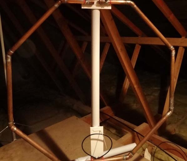 Octagonal magentic loop antennas that work from 20 to 10 meters with pictures and efficiency reports by G1KEA
 -
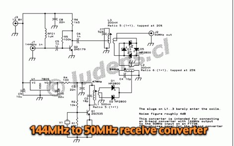 A simple accessory for a satellite station, that allows using a 6 meter capable radio in conjunction with a typical S-band to 2 meter converter
 -
 Operating as a local amateur radio club, the Wireless Association of South Hills (WASH) provides a community hub for hams in the Pittsburgh, PA area, identified by the N3SH callsign. The club engages in a range of activities including the Annual Field Day, the PA QSO Party, and a 2 Meter Contest, fostering participation in various aspects of the hobby. WASH also supports local ARES/RACES efforts, highlighting the critical role of amateur radio in emergency communications during disasters, and facilitates ARRL/VEC exam sessions for new licensees. Beyond contests and emergency preparedness, WASH hosts club picnics and an annual hamfest, promoting social interaction among members. The club maintains VHF/UHF repeaters, which are essential for local communication and extending range for members. Regular activities include a Monday evening WASH NET at 8:00 PM, providing a consistent on-air gathering point. The club's focus on both recreational and public service aspects of amateur radio, from making new friends to providing vital disaster communications, underscores its comprehensive approach to the hobby.
 -
 A few pictures of an homebrew magnetic loop RTX antenna project, working from 30 to 12 meters with excellent results
 -
 Operating the _Icom IC-746_ HF/VHF transceiver often presents specific technical questions, and this resource compiles a comprehensive Frequently Asked Questions (FAQ) document in an ASCII text format. It details common inquiries and solutions related to the rig's functionality, accessories, and potential modifications. The content is structured into distinct sections addressing general information, power supplies, antennas, microphones, keyers, amplifiers, TNC integration, and optional IF filters. The FAQ provides practical guidance on topics such as configuring the internal automatic antenna tuning unit (ATU), selecting appropriate power supplies, and understanding microphone pin-outs. It also delves into advanced subjects like computer control via CI-V, wiring for PSK31 operation, and troubleshooting common issues like low S-meter readings on 2m FM or loose tuning shafts. Specific questions cover the installation of optional IF filters, comparing Inrad versus Icom filters, and optimizing filter combinations for various modes. Furthermore, the document outlines various hardware and firmware modifications, including those for increasing monitor volume, replacing LCD driver transistors, and implementing a "poor man's TCXO." It even touches upon untested modifications, such as replacing PIN diodes in the demodulator. The FAQ also lists manual errata and discrepancies, offering a robust knowledge base for IC-746 owners seeking to optimize their station or resolve operational challenges.
 -
 The page provides detailed instructions on how to build a 60 meter End Fed Half Wave Antenna Tuner, with large pictures and diagrams. It is aimed at amateur radio operators looking to construct their own antennas for the 60 meter band.
 -
 KB9AMG's Top WSPR Spots presents a focused online tool for monitoring **2-way WSPR reports**, specifically detailing propagation data from February 2026 through March 2026. This resource aggregates _WSPRnet_ data, allowing radio amateurs to observe weak signal propagation conditions across various bands. The interface is straightforward, presenting callsigns, frequencies, signal-to-noise ratios, and distances for each reported contact, which is crucial for understanding current band openings and signal paths. The utility of this WSPR spotter lies in its ability to quickly visualize global propagation. Users can identify active stations and assess signal viability over long distances, with reports often showing contacts spanning thousands of kilometers. For instance, a typical WSPR report might indicate a signal from Europe reaching North America with a _SNR_ of -25 dB, demonstrating effective low-power communication. This data is invaluable for planning DX operations or evaluating antenna performance under actual propagation conditions.
 -
 A presentation of the Yagi Antennas, and other interesting tid-bits by Brian Mileshosky. The document provides an in-depth exploration of the Yagi-Uda antenna, detailing its historical development, design principles, and performance characteristics. Originally described in the 1920s, the Yagi antenna features a driven element and parasitic elements, including reflectors and directors, which collectively determine its behavior. The document highlights how element lengths, diameters, and spacing influence gain, impedance, and directivity. It also discusses the antenna's reciprocal nature and presents data on typical gain values for various element configurations. Additionally, the text covers practical considerations, such as the construction of a "Tape Measure Yagi" for amateur use, and touches on related antenna types like dipoles and their application in Near Vertical Incident Skywave (NVIS) communication.
 -
 A home made 50 MHz KW power amplifier project with picture and PCB schematic by W6PQL
 -
 Presents a concise guide for Amateur Radio operators participating in Jamboree-on-the-Air (JOTA), an annual event connecting approximately 500,000 Scouts and Guides worldwide via ham radio. The resource details how to initiate a voice contact, including the use of "CQ Jamboree JOTA" and proper signal reporting with the RST system. It also outlines the typical exchange information, such as name, QTH, Scout rank, and age, encouraging participants to practice their responses. Authored by Bill Wetherill, N2WG, the brochure provides a practical phonetics chart and a comprehensive Morse code dictionary, including punctuation and prosigns like AR and SK. It clarifies rules for third-party operation under the direct supervision of a licensed operator, noting restrictions on international contacts without specific government agreements. Additionally, the guide lists recommended World Scout Frequencies for SSB and CW across 80, 40, 20, 17, 15, 12, and 10 meters, emphasizing courteous operating procedures. It includes a section on common Q-signals like QRM, QRN, and QSL, alongside the Amateur's Code, which stresses considerate, loyal, progressive, friendly, balanced, and patriotic conduct.
 -
 The 160-meter amateur radio band, spanning 1.8 to 2 MHz, was historically the lowest frequency amateur allocation until the introduction of the 630-meter and 2200-meter bands. ITU Region 1 allocates 1.81–2 MHz, while other regions use 1.8–2 MHz. This band, often called "Top Band" or "Gentleman's Band," was established by the International Radiotelegraph Conference in Washington, D.C., on October 4, 1927, with an initial allocation of 1.715–2 MHz. Effective operation on 160 meters presents significant challenges due to the large antenna sizes required; a quarter-wavelength monopole is over 130 feet, and horizontal dipoles need similar heights. Propagation is typically local during the day, but long-distance contacts are common at night, especially around sunrise and sunset, and during solar minimums. The band experienced a resurgence after the LORAN-A system was phased out in North America in December 1980, leading to the removal of power restrictions.
 -
 The Superantennas MP-1 portable HF antenna is analyzed for its design and field performance, particularly its high-Q loading coil and 3/8-inch mounting. The review details the antenna's construction, including an 8-inch vertical section, a large-diameter loading coil tuned by a sleeve, and a 4-foot whip that disassembles into six rods for transport. Initial testing with the supplied 10-foot ribbon cable "ground plane" yielded poor SWR and RF hot conditions, indicating an inadequate ground system. Further experimentation with longer radials and resonant counterpoises for each band improved matching and eliminated RF hot issues, but introduced significant operational complexity. The author notes the difficulty in optimizing both counterpoise length and coil setting without an antenna analyzer, and the sensitivity of the MP-1 to counterpoise deployment. The review also discusses the recommendation to tune for maximum received signals rather than minimum SWR, often necessitating an external ATU due to the antenna's typical low impedance. The **MP-1**'s critical dependence on resonant counterpoises for effective operation, especially when elevated, is highlighted as a major drawback for portable use. The author ultimately sold the antenna, concluding that despite its sound technical design, its fussy nature and the need for extensive counterpoise management or an ATU detract from its portability and convenience compared to simpler, less expensive dipole solutions. The **Superantennas MP-1** is deemed a flawed portable antenna, requiring considerable effort to achieve its claimed performance.
 -
 Morse code speedometer project using the 16F84 PIC