Search results
Query: simple antenna
Links: 253 | Categories: 1
Categories
-
 A homemade Magnetic Loop antenna from a spare 3m length of RG213 working from 30m to 15m with a 130pF tuning capacitor
 -
 A simple and low cost multiband vertical hf antenna covering 5 bands (20m-10m) from an old CB antenna
 -
 A Center-Fed Half-Wave Dipole is probably the simplest of antennas to construct and use. It is usually suspended between two supports, from it's end insulators, and has the feedline hanging from the center.
 -
 A really simple receiving antenna for 80 and 160 meter dxing by WA2WVL
 -
 End-Fed Half-Wave Antennas (EFHWAs) are analyzed for their utility in portable QRP operations, emphasizing their simplicity, efficiency, and predictable radiation patterns compared to other portable antenna types. The discussion contrasts EFHWAs with vertical antennas, random length wires, and center-fed dipoles, highlighting the common pitfalls of each, such as ground system dependency for verticals and feedline issues for dipoles. The article details the electrical half-wavelength calculation using the formula L (Ft) = 468/F(MHz) and explains how EFHWAs can be resonant on harmonic frequencies, enabling multiband operation. Various deployment configurations are presented, including the inverted L, inverted Vee, sloping wire, and vertical setups, each with specific advantages for radiation angle and polarization. For instance, a vertical EFHWA offers a low angle of radiation suitable for DX contacts without requiring an extensive ground system. The resource also addresses the counterpoise requirements, suggesting a quarter-wavelength wire or connection to a metallic structure for decoupling. A schematic diagram for a simple parallel-tuned circuit tuner, based on the _Rainbow Bridge/Tuner_ design, is provided, detailing component values for 30 and 40 meters, including a 6 microhenry toroidal inductor and a 20-100 picofarad mica compression capacitor. The tuner's adjustment process for SWR matching is also outlined.
 -
 Details a practical QRP wattmeter construction, leveraging a simplified SWR meter design by JA6HIC. The project focuses on a forward-only power measurement circuit, providing a functional instrument for RF power levels from milliwatts up to 5 watts. It maintains a 50-ohm input and output impedance, suitable for typical QRP transceivers and antenna systems. The resource includes the schematic for the "VSW" (Very Simple Wattmeter) and outlines a six-step alignment procedure. This calibration process involves using a known RF source up to 5W, setting full-scale deflection, and marking power increments. It also addresses minimizing frequency effects on readings with a 100pF trimmer capacitor, noting that measurement error is highest at the lower end of the scale. Construction notes mention using a piece of RG-213 coaxial cable for the inductance and coupler, with the wattmeter assembled in early 2003. The author provides an example measurement showing 0.8W into a dummy load and 1W into a 3-element beam.
 -
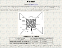 Two element X-Beam is a high-performance broad-band antenna that is ideal for Ham radio operators with limited space. X-Beams are inexpensive and easy to build. The performance of the simple X-beam is amazingly similar to larger, more conventional antennas by 4S7NR
 -
 It is very easy to create a simple 1/2 wave dipole, all you need is some lengths of wire such as the core of some mains flex or even a straightened out metal coat hanger, some co-ax cable and a connector for your scanners antenna input
 -
 Simple, inexpensive and easy to erect, this antenna provides directivity, low angle radiation and a small gain on a number of HF bands.
 -

-
 This simple antenna is capable of remarkable results on 160, 80 and 40 metres. Forming a triangle from around 50 feet of satellite TV coaxial cable, the top of the triangle can be as low as 15 feet, and the lower side just high enough to prevent a passer by hanging themselves
 -
 5 Band 1/4 wave Telescopic Antenna. The 20m to 10m, antenna is simple and cheap to make, and has a performance that matches commercial antennas but at cost considerably lower. The design was purposely based on a telescoping fibre glass fishing rod as this allows it to be easily stowed away in the car.
 -
 A simple to build Yagi 2 element antenna for 15 or 20 meters band by 9m2mso
 -
 Antenna that's simple, inexpensive lightwiight and easy to install
 -
 Described is a simple inverted-V antenna which, when used with a balanced ATU, can be used on all the main Radio Amateur HF bands (80, 40, 20, 15 and 10m). The cental support is made in such a way that the wire can be coiled up for storage when the antenna is taken down.
 -
 Various tests and designs, with photos of home made EH Antennas,simple and networked, and also sone CAN Antennas.
 -
 How to create a simple but effective half wave dipole, illustrated instrucions on how to build wire antennas
 -
 A simple drawing of a shortened antenna for 40 meters by using a PVC tube
 -
 Simple DIY stealth apartment antenna for 20m and 40m. It is basically a ZigZag quarter wave dipole antenna
 -
 A 40 ft vertical dipole antenna that can cover HF Bands from 80 to 10 meters winding a dipole in a 12m HD telescoping fiberglass pole
 -
 The page describes the construction of a simple omnidirectional, vertically-polarised dipole antenna for two metres using coaxial cable. It can be used indoors or outdoors, with no extravagant gain claims. The project is low-cost and can be completed in about 20 minutes.
 -
 Don't buy or build a semi-vertical trap antenna until you read this article! If you can use a drill, saw and screwdriver this is a simple project.
 -
 The Homebase10 is a simple to make wire halo antenna for 10m (28MHz) built using parts available from the local DIY store.The resulting antenna is very effective on 10m despite its small size and light weight.
 -
 This page describes a simple way to determine the main RF characteristics of a Wifi (IEEE802.11b/g wireless LAN) antenna.
 -
 A simple base loaded quarter wave vertical, which can be used on a car or portable by G3YCC
 -
 This is a simple calculator for solving the antenna wire catenary between to end points given the design wind speed, mass per unit length of the wire, wire diameter and Gross Breaking Strength of the wire.
 -
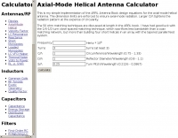 Simple implementation of the ARRL Antenna Book design equations for the axial-mode helical antenna.
 -
 Amateur Television (ATV) operations, particularly within the Arizona region, require dedicated resources for technical information, operational guidance, and community engagement. This club provides a focal point for hams interested in transmitting and receiving video signals on amateur bands. Members engage in local ATV repeaters, participate in technical discussions, and share knowledge on video modulation schemes, antenna designs, and station configurations. The club supports activities ranging from local simplex contacts to wider area repeater usage, fostering skill development in this specialized mode. The organization maintains a roster of club officers and offers membership opportunities to local amateurs. It also curates offsite links to other ATV resources, expanding the knowledge base available to its members and the broader amateur community. The club's emphasis on ATV helps propagate interest and technical expertise in a mode that combines traditional RF engineering with video technology.
 -
 A simple antenna that can be erected very fast, only need one center support, and do not take up much storage room. Works from 40 to 10 meters band
 -
 A simple, cheap, efficient tv antenna that you can make yourself.
 -
 Put up the longest dipole you can fit, feed it with open wire line, connect it to the balanced output of your tuner and poof! Instant multiband antenna. Is life really that simple?
 -
 D3+ High Performance Antennas for Field Day. This article describes versatile broadband wire antennas. These antennas will double your effective radiated power over a dipole, will be easy and inexpensive to build and install, and will be simple to match.
 -
 The project outlines the process for constructing a low-power FM broadcast transmitter using a Raspberry Pi Zero, a simple wire antenna, and battery power. It details the software installation steps for PiFM and MPG123, essential for generating and transmitting audio. The resource provides instructions for configuring the Raspberry Pi to broadcast FM signals, including command-line operations for initiating transmission and playing audio files. It specifically focuses on the Raspberry Pi Zero's capabilities for this application, highlighting its cost-effectiveness and minimal hardware requirements. The content presents a practical, hands-on approach to creating a basic FM transmitter, suitable for short-range, experimental broadcasting. It includes guidance on testing the FM output and ensuring proper operation of the software components. The project emphasizes the use of readily available components and open-source software to achieve functional RF output.
 -
 This article describes the design of an antenna for local contacts on 7MHz, including a simple and efficient matching system that presents a 50 ohm load to the transceiver.
 -
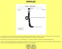 The simple dipole is perhaps the best antenna for consistent performance. Basic page on dipoles by G3PTO
 -
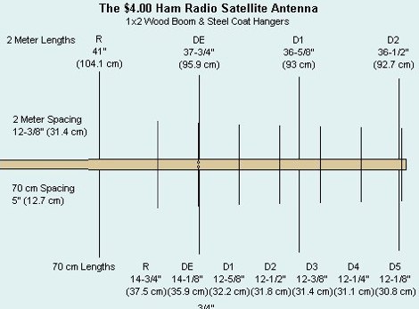 Simple, inexpensive and lots of fun! Here is an easy to make home brew antenna that can get you on the air working satellites or be built for use as a portable hand held antenna to extend the range of your HT.
 -
 Demonstrates the construction of two distinct wideband RF preamplifiers, detailing their component requirements and performance characteristics. The first design leverages monolithic microwave integrated circuits (MMICs) such as the MAR-6, MAR-8, or PGA103, offering a broad frequency response from DC to 2 GHz with a gain of 22.5 dB at 100 MHz and a noise figure typically below 3 dB. This MMIC-based amplifier incorporates protection against power supply transients and features a 50 Ohm input/output impedance, operating from an 8-20 volt supply with low current drain. The second preamplifier design utilizes a BSX-20 transistor, providing amplification across the 14 MHz to 550 MHz range. This simpler, more economical build achieves an average gain of 12 dB at 145 MHz and a noise figure of approximately 1.1 dB. It operates from a 7-15 volt battery supply with a current draw of 6 mA. Both projects emphasize critical construction techniques, such as maintaining short RF connections, ensuring 50 Ohm impedance paths, and mounting the circuit within a shielded enclosure to optimize performance and minimize noise. The resource also discusses phantom power options for antenna-mounted preamplifiers and precautions for use with transceivers, including output protection diodes and static bleeders.
 -
 A simple beam antenna offering good performances on 3 bands by 9m2mso
 -
 The half wave dipole antenna is a simple and practical antenna model that consists of a half wavelength long centre fed conductor.
 -
 A _Topfkreis_ antenna, also known as a "bicycle pump" antenna, is presented as a simple vertical design for the 70 cm band. This variant of the J-pole antenna is notable for not requiring a ground plane, simplifying deployment. The construction details specify using aluminum tubing for the radiating element, with precise measurements for the quarter-wavelength outer tube (32 mm diameter) and the three-quarter wavelength inner sliding tubes (10 mm and 8 mm). Feeding is via a 50-ohm coaxial cable connected 90 mm from the base of the central tube. This design can achieve a gain of **4 to 6 dB** when properly tuned using the adjustable radiating element. The article details the fabrication of a critical aluminum washer, suggesting a method using a hole saw and a drill press as a lathe for precise adjustment. The illustrated example is specifically for the 70-centimeter band, and the author, Pop, clarifies construction points in the comments, including material choices and assembly techniques, ensuring a robust build for VHF/UHF operation.
 -
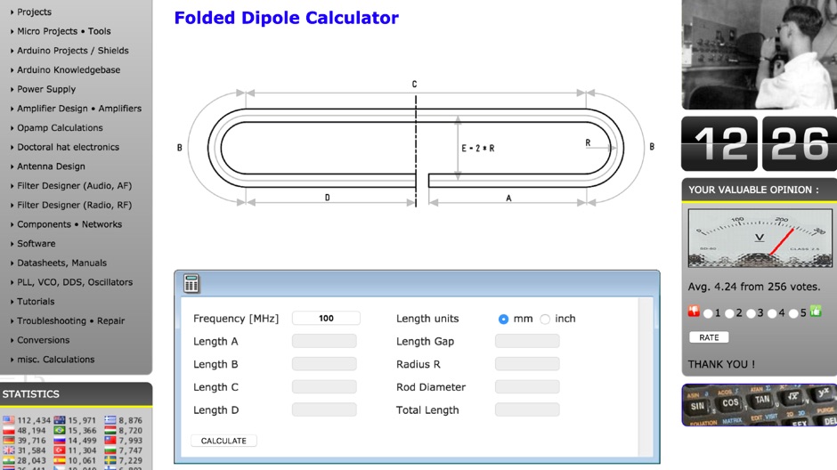 A simple online folded dipole antenna calculator
 -
 Simple, easy to build, low cost, compact, multiband By Robert Wilson, AL7KK
 -
 A simple quarter-wave length vertical for 40m band using a 12 m spiderpole
 -
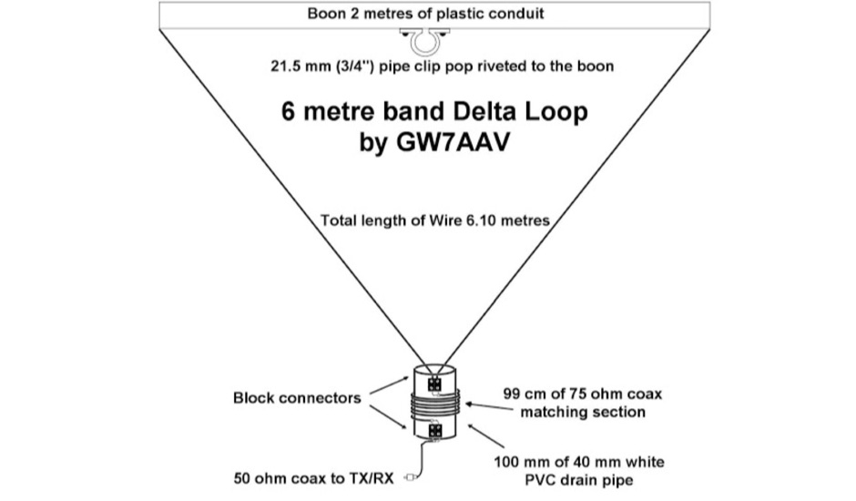 A simple delta loop antenna antenna for the six metre amateur radio band
 -
 A five element quad antenna for 144 MHz DIY Project. This 2 Meter 5 Element Quad antenna was modeled using EZNEC, with a boom from a UHF TV antenna and CPVC pipe for spreaders. Constructed for 146MHz, it exhibits a gain of 10.7dB and an impedance of 75 ohms. Real-world results surpass the HT antenna, reaching over 20 repeaters up to 75 miles away. The design, costing around $10, employs simple tools for assembly.
 -
 A simple 7 bands off-center dipole wire antenna designed to work on 80 meters band and that can cover also 40m 30m 20m 15m 12m 10m with acceptable SWR
 -
 A multiband quarter wave vertical antenna that works on 5 bands.
 -

-
 A simple & effective antenna pre-amp for 10m. Band (28-29.7 MHz)
 -
 GW4ALG's _136 kHz Pages_ document the evolution of vertical antennas for the 2200m band, starting with a prototype mounted on a house wall. This initial design, despite achieving the first **395 km** GM-GW QSO, suffered from significant insulation breakdown, high RF losses due to proximity to the house, and difficult tuning adjustments. The author details the challenges of maintaining resonance and matching with a variometer in the loft, noting that adding three earth spikes offered no measurable improvement over a simple water tap connection. The subsequent experimental 12m vertical, relocated away from the house, significantly reduced dielectric losses and proved far more effective. This antenna enabled GW4ALG to set a world DX record on 136 kHz with a **1916 km** QSO to OH1TN, and an intra-UK record of **703 km** to GM3YXM/P. The resource further explores the use of helium-filled balloons to extend the vertical radiator, achieving heights up to 27m, typically 20m, for enhanced low-band performance. Practical advice on balloon types, inflation, and critical insulation between the wire and balloon is provided, emphasizing safety and avoiding arcing.