Search results
Query: 6m antenna
Links: 168 | Categories: 1
Categories
-
 Crank-up(telescopic) and tilt-over tower, Ring rotator for mounting an extra antenna, from 16m to 42m, Strong safe and smooth, Radio communication and commercial tower.
 -
 C-Poles for 20m and 6m, it is a folded half-wave dipole with an asymmetrical tapped 50-Ohm-point in the lower part of the antenna. Design hints by DK7ZB
 -
 This is a video review of the yaesu ft-450 amateur radio transceiver. This radio operates on hf and 6m with a built in antenna tuner.
 -
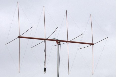 Article by G4AON about a 4 and 2 Element Quad Antennas for the 6m band
 -
 Presents SWR analysis of an **Alpha-Delta DX-LB Plus** multiband wire antenna, installed as an inverted-V at 40 feet with ends at 15 feet, using an RigExpert AA-54 analyzer. The resource provides a full SWR sweep from 0.1 MHz to 54 MHz, followed by detailed SWR graphs for individual amateur bands including 160m, 80m, 40m, 30m, 20m, 17m, 15m, 12m, 10m, and 6m. The analysis highlights the narrow bandwidth on 80m and 160m due to loading coils, necessitating tuning for specific operating frequencies. It notes excellent SWR performance across the entire 40m band and good results on 10m, also requiring tuning. The author shares personal experience with the antenna, including a 17,000 km QSO on 20 meters, and discusses plans to replace it with a homebrewed parallel **fan-dipole**.
 -
 A magnetic loop antenna for the VHF band, featuring a high gain that can be compared to a quarter wave vertical antenna
 -
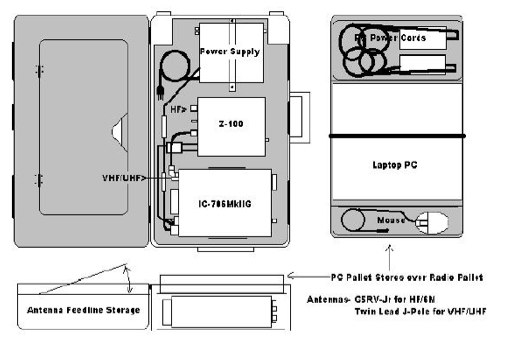 A Portable 100 watt radio station setup composed by a 706MKII transceiver, Z-100 antenna tuner and power supply by N1GY
 -
 50MHz Collapsible 2 Element Mini Beam antenna, an overview the development of the 6MBA.
 -
 A 200 kHz bandwidth digital transmission system for image transfer in the Amateur Service is under development, specifically targeting VHF allocations. John B. Stephensen, KD6OZH, leads this project under an FCC Special Temporary Authority (STA) valid until September 10, 2006, authorizing emissions up to 200 kHz bandwidth in the 50.3-50.8 MHz segment. Current regulations typically limit bandwidths to 20 kHz on VHF amateur bands, making this STA crucial for testing wideband digital modes. The modem, a modified **OFDM** (Orthogonal Frequency Division Multiplexed) unit, was initially tested on the 70-cm band. It splits a high-rate data stream into multiple low-rate subcarriers to mitigate multipath echoes. The system uses a DCP-1 card with a Xilinx XC3S400 FPGA and Oki Semiconductor ML67Q5003 microcontroller. The transmitter, located at 36d 46m 30s N, 119d 46m 22s W, generates 150 WPEP into an 8 dBi gain vertical antenna, while the mobile receiver uses a Ham-stick. Three data formats for 50, 100, and 200 kHz channels are being tested, with encoded data rates of 96, 192, and 384 kbps. Verilog code for the VHF OFDM modem is 95% simulated, with modifications from the UHF version including increased filter coefficient precision and a change from Ungerboeck **TCM** to BICM for improved performance over fading paths. Final tests will involve one-way over-the-air measurements of bit error rates and coverage area.
 -
 This Magnetic Longwire Balun (MLB) makes it possible to efficiently use a coaxial lead-in cable with all forms of longwires, T-forms or other types of wire antennas, without the need for an antenna tuner.
 -
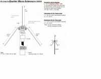 A quarter wave antenna with dimensions for uhf and vhf bands
 -
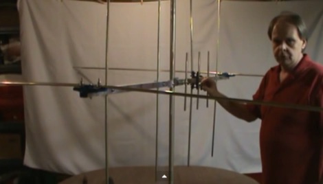 6m/2m/70cm Yagi Antenna Built from Old TV Antenna This turned out to be a great little antenna. It works the 6 meter, 2 meter and 70 centimeter bands. You can use one common feedpoint or two seperate feedpoints depending on how you would like to connect this antenna to your transceiver.
 -
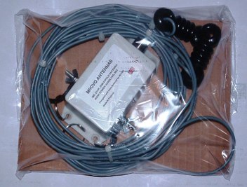 M0CVO Antennas, amateur radio antennas for fixed station or portable operations, HF/6m all are catered for. The antennas produced by us are all manufactured by Nigel Booth, M0CVO
 -

-
 This 6 meter 2 element yagi antenna is simple, compact and effective antenna for 50 Mhz. The design antenna was optimized with AO for best match to 50 ohms, no matching network. A choke balun is recommended to decouple feedline currents.
 -
 This simple project, based on the orginal CobWebb-Antenna model, is about an horizontally polarized, omi-directional antenna for the six meter band.
 -
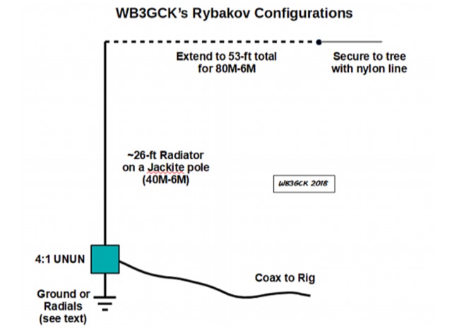 An article about the Rybakov 806 Vertical antenna. The classic Rybakov configuration is a 7.6m or 8m ( aprox 25 or 26 feet) wire fed through a 4:1 UNUN
 -
 A J-pole antenna plan for 50 MHz based on the DK7ZB design
 -
-
 Documents the OC1I and OC6I IOTA DXpeditions to Peru, specifically highlighting operations from SA-098 (Isla La Leona) and SA-076 (Isla Lobos de Afuera). The OC1I team logged over **8000 QSOs** from SA-076, while OC6I made 1400 QSOs from SA-098, despite challenging propagation conditions. The resource details the equipment used, including an _IC-7000_, an IC-706mkIIG, and a TS-440SAT, along with various antennas such as a 160m dipole, FD4, G5RV, and a multi-band vertical for 17m, 20m, 30m, and 40m. The DXpedition dates are specified: OC6I operated from SA-098 between December 28 and December 30, while OC1I was active from SA-076 from January 2 to January 7. Both operations are confirmed as valid for IOTA credit. The page also includes a video link for the OC6I operation and a photo gallery from the DXpedition. Feedback is welcomed, and the webmaster is identified as Bodo Fritsche, DL3OCH.
 -
 9M6MU Alfons details his family's efforts to establish an independent, self-sufficient home at Eagle Plateau in Borneo, a 50-acre highland property. The resource highlights their integration of **solar photovoltaic panels** for power generation, alongside managing water supplies, organic gardens, and fruit trees. It covers the practical challenges and rewards of living off-grid, including maintaining power generators and addressing infrastructure needs, all while pursuing the hobby of amateur radio. The narrative emphasizes a holistic approach to healthy living and nature conservation, reflecting the family's aspirations for an ideal ham world. Alfons and his XYL Doris share their experiences in building shelter and antenna farms, showcasing their dedication to independence and sustainable practices away from the conventional grid. The site also references the Hillview Gardens Amateur Radio Club, suggesting community involvement.
 -
 Installing a mobile rig in a vehicle requires careful planning and execution to ensure optimal performance and safety. The process begins with selecting the right equipment, such as the ICOM IC706MKII for low bands and the ALINCO DR-610 for VHF/UHF operations. Proper mounting is crucial; both radios are strategically placed under the back seat of the Silverado, allowing for a clean installation while maintaining passenger comfort. The Hustler antenna, equipped with various resonators, ensures coverage across multiple bands, while the LDG automatic antenna tuner fine-tunes the match for efficient operation. A remote head for the tuner enhances accessibility, making adjustments easier while driving. Each step of the installation is documented to provide insights and tips for fellow operators looking to enhance their mobile setup. The experience shared here reflects practical knowledge gained through hands-on work, aiming to inspire others in the ham community to undertake similar projects.
 -
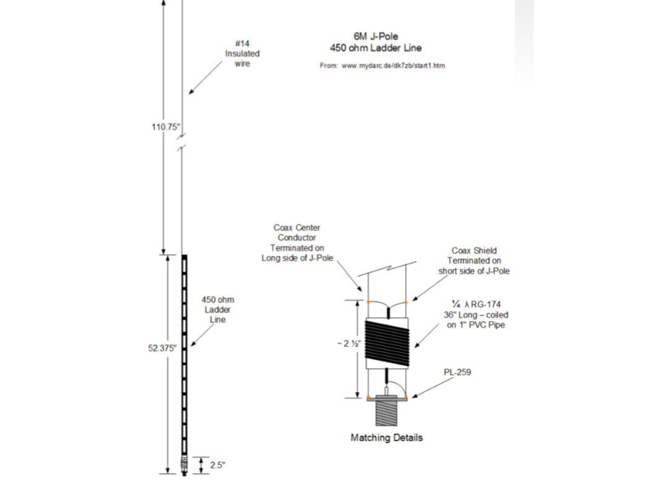
 6 Meter J-Pole from 450 Ohm Ladder Line a quickie project
 -
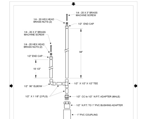
 This antenna is designed for stations having a difficult time putting a decent signal on 160M from small or CC&R d lots. It is a 24.5 ft. vertical antenna, made from three 10 ft. PVC sections bolted together, and half wavelength of antenna wire helically wound around the PVC sections.
 -
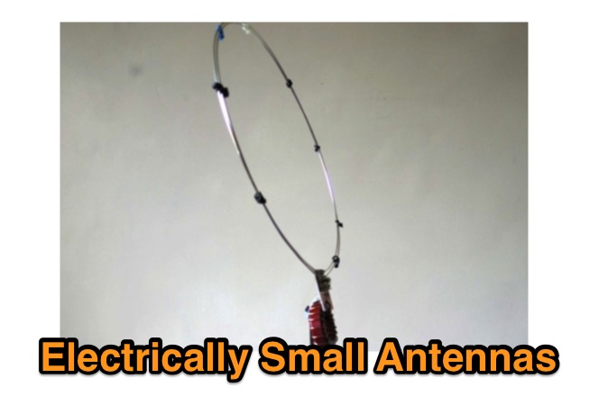 An antenna system is electrically small if it's enclosing sphere is <λ/2π. So a 10m band antenna of under 1.6m long qualifies.
 -
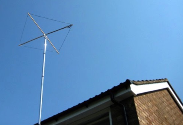 The Homebase-10 is a wire halo antenna for 10m built with DIY store parts, effective despite its small size. Includes a dual-band version for 10m and 6m with gain around 0 to -2dBd, near omnidirectional pattern, and horizontal polarization. Overview based on a 2008 Practical Wireless article.
 -
 Constructing a multi-band fan dipole for HF operation presents unique challenges, as VE2XIP demonstrates through his 2012 project to replace an existing commercial antenna. He details the process of calculating wire lengths using the 468/frequency formula, emphasizing the critical importance of equal leg lengths for each dipole element. The author shares practical insights gained from building at ground level, noting how elevation impacts resonant frequency and SWR, particularly for lower and higher bands. VE2XIP's experience highlights the iterative nature of antenna tuning, starting with the lowest frequency band (80m) and working upwards. He provides a specific example of trimming calculations and offers a clever tip for accurate wire removal. The article also touches on the mechanical aspects, such as dowel spacing for wire support and the benefits of a pulley system for repeated raising and lowering during the tuning process. Field results showed significant performance gains over the previous Alpha-Delta DX LB Plus, with **20 dB over 9** signal reports on 80m compared to 57. The project cost around **$100** for hardware, proving a cost-effective alternative. The author also discovered a bonus 6m capability and achieved an inverted-V _obtuse angle_ of approximately 115 degrees, contributing to a surprisingly stealthy installation.
 -
 The antenna described in this article is for 50 MHz, but the design can be scaled for any band, including VHF, UHF, or even the higher HF bands. The antenna is nothing more than a square loop of wire, approximately 30" (or ~76cm) per side. The loop is fed in the middle of one side, and the opposite side to the feed point has a gap in it.
 -
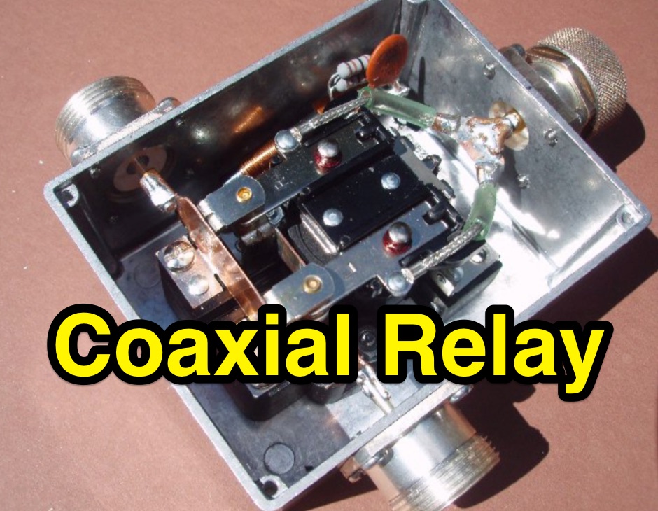 Build a SPDT coaxial relay that can be used as a main Transmit/Receive relay or an A-B switch to select between two different 6m antennas
 -
 Sort of similar to the one of the 6m omni. Instead of using twin-lead, this design makes use of a more or less regular double bazooka antenna (coaxial dipole). Your attention shall be drawn to the available standart literature, such as Rothammel. In order to "compute" the dimension, Karl Rothammel mentioned that the total length of the dipole shall be 95% of the free-space wavelength. The short-circuit bridges (closing the folded dipole) are to be placed at a distance-fraction being equal to the velocity factor of the coax cable used, which will be 66% using RG-58 or RG174.
 -
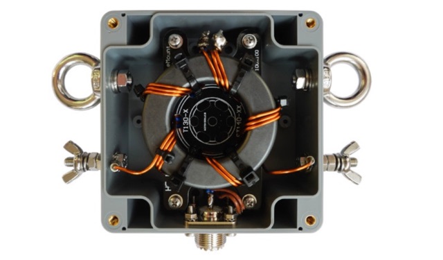 This Guide helps you to build the 1:2 BalUn 600 Watts DIY kit step by step. If a delta-loop or quad-loop antenna is powered with a coax cable from the transceiver it is necessary to use a 1:2 BalUn. This 1:2 BalUn uses a symmetrical 1:2 impedance transformer.
 -
 A fand dipole antenna home made for the 7,14,50 MHz. This article descbribes how to homebrew the antenna, hot to setup and some SWR measurements.
 -
 A multi-band off centre fed dipole, designed to operate on all bands from 40m (7MHz) to 6m (50MHz). Author claims it will operate on 40, 30, 20, 17, 15, 12 and 10m without an ATU (SWR <3:1) plus 6m with an ATU.
 -
 A homemade Jpole antenna for 70 cm band made with 6mm copper pipe
 -
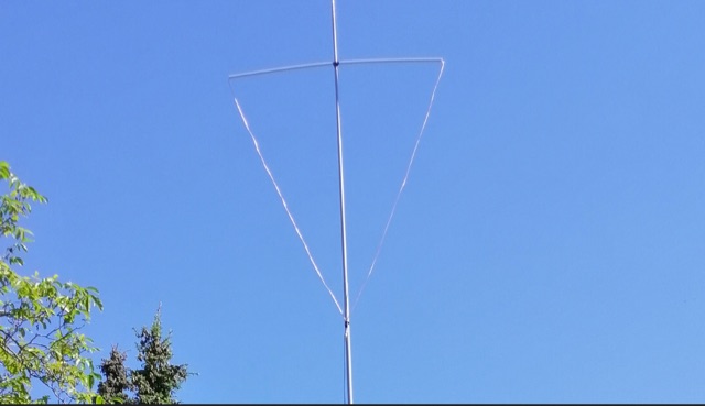 A homemade delta loop antenna for six meters band in German
 -
 The Tri-pole antenna, a clever modification of a standard dipole, allows for dual-band operation by integrating a third element. This design effectively shortens the overall dipole length by 10 to 20 percent, simplifying antenna rotation and offering a compact footprint. KK4OBI's article delves into the operational principles, using a 6 and 10-meter Tri-pole as a primary example, and provides comprehensive instructions for constructing any Tri-pole antenna within the 6 to 15-meter range. Key to the Tri-pole's performance is its off-center feed, necessitating a common mode choke at the feed point for optimal tuning and reduced noise. The author outlines a methodical approach to determining element dimensions, starting with a vertical element frequency calculated as 0.47 times the sum of the desired upper and lower band frequencies. This calculation, along with K-values derived from trend lines, guides the initial lengths for the horizontal arms, demonstrating how a 10m-6m Tri-pole can achieve a total horizontal length 78% shorter than a conventional 10-meter dipole. Tuning and balancing are critical, with the article detailing adjustments to arm lengths and the vertical element to achieve balanced SWR values, as validated through 4NEC2 simulations. Radiation patterns are analyzed at various elevations, showing gains around 5.7 dBi and favorable take-off angles for DX contacts. Construction details specify aluminum tubing dimensions, U-bolts, and an SO-239 connector, emphasizing the importance of a ferrite-based choke for wideband operation.
 -
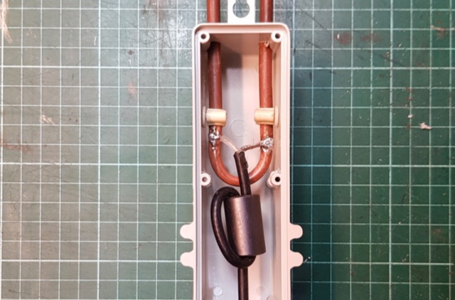
 A homemade j-pole antenna for six meters band, designed to work on local repeaters, and working on the 52-53 MHz. Includes a list of needed materials and detailed description on assembling the copper tubes used to build this antenna.
 -
 Complete plan for making a 2-meter J-Pole antenna. This drawing in PDF File includes a detailed list of the parts needed to assemble the Jpole antenna for 144 MHz.
 -
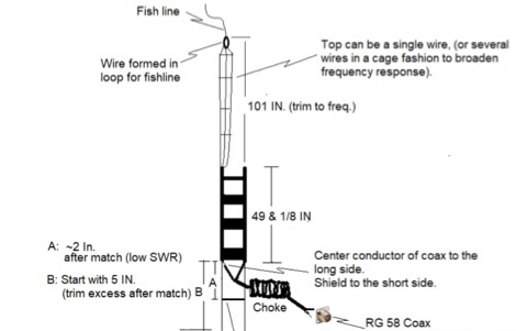
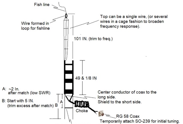
 This J-Pole is mounted on a fishing rod. The radiator L1 is an isolated copper-wire with a length of 281,5 cm while the quarter-wave matching sector L2 is made with 450-Ohm-Wireman-cable
 -
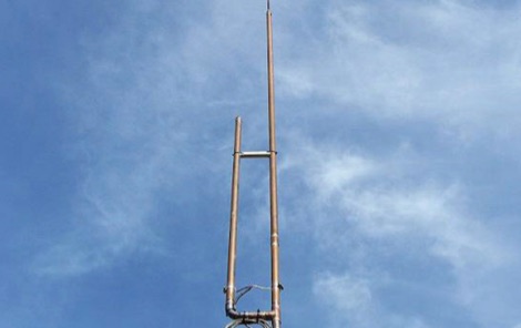
 This article provides details on building a 6 Meter J-Pole antenna using PVC pipe for an enclosure. This antenna uses flat 450 ohm Window Line for the tuning stub.
 -
 A review of the SteppIR UrbanBeam antenna a two element Yagi antenna working 40-6 meters. The UrbanBeam is a good choice for those thare are limited by lot size, regulations, city regulations.
 -
 A vertical antenna for 160 meters band based on the K6MM vertical with some enhancements and modifications on the main capacitance hat
 -
 A 30 cm antenna for the six meters band in japanese
 -
 This article provides details on building a 6 Meter J-Pole antenna using PVC pipe for an enclosure.
 -
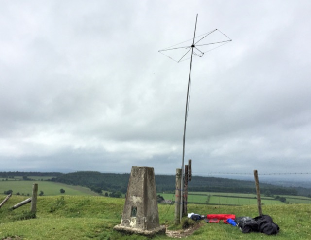 Bring the six meters with you during your hoilidays. This article features a portable moxon antenna for 50 MHz used for sota portable operatios
 -
 Explains the fundamental purpose of a repeater, detailing how these automated relay stations overcome distance and terrain limitations for VHF/UHF communications. It traces the historical development from early Bell Telephone Labs "relay" stations in 1922 to Art Gentry, W6MEP's, pioneering K6MYK amateur radio repeater in the mid-1950s, which remains active today. The resource clarifies the distinction between simplex and duplex operation, including the unique function of a "parrot repeater" for single-frequency recording and playback. Delving into the internal workings, the guide breaks down a repeater into its core components: the antenna system, feedline (often _Heliax_ or hardline for minimal loss), duplexer, receiver, transmitter, and controller. It emphasizes the critical role of the duplexer in preventing receiver desensitization by isolating transmit and receive signals, even with distinct frequencies. The discussion highlights the importance of high-performance, durable antennas and low-loss feedlines, citing examples of equipment installed in the 1960s and 1970s that are still in perfect working order. Operating a repeater is also covered, with an explanation of frequency offset (e.g., the 600 kHz standard for 2 meters) and the function of _CTCSS_ (PL tone) for access. It outlines standard input/output offsets for various bands, from 6 meters to 23 centimeters, while noting regional variations. The guide also touches on features like autopatch and Digital Voice Recorders (DVRs), providing a solid foundation for understanding repeater technology and usage.
 -
 a 20M quarter-wave vertical antenna with a 6m telescopic mast, 1:1 balun, and spiral-wound driven element. Designed for QRP at 14.285 MHz, the antenna’s performance exceeded expectations, delivering low SWR and surprisingly quiet reception. Initial testing yielded successful contacts with European stations and EC1KR, showcasing its effectiveness. Compact and easy to deploy, the antenna promises to be an excellent portable solution for future hilltop operations.
 -
 Originally designed by John Kraus, W8JK in about 1940, this antenna has some interesting properties. The W8JK antenna is 2 (Two) centre-fed double-dipole fed by a pair of anti-phase signals. Small size, simple antenna, offer nice performance but need a tuner. Tested in this project from 30m to 6m bands
 -
 The DK7ZB-Dualband-Moxon-Beam provides a compact, high-performance antenna solution for 28 MHz and 50 MHz operations, utilizing a single 50-ohm feedpoint. This design functions as a mini-beam on 10 meters, achieving a gain of **4.0 dBd** with a front-to-back ratio of _30 dB_, while operating as a 2-element Yagi on 6 meters, yielding a gain of **4.3 dBd** and an 11 dB F/B ratio. The antenna's dimensions are approximately two-thirds that of a full-size 10-meter beam, making it suitable for smaller spaces. Construction details include a parts list specifying aluminum tubes of various diameters and lengths for the reflector and radiator elements. Builders like Aleks (S54S) and Marcio (PY2OK) have successfully replicated the design, with Aleks noting the utility of bending corners during assembly. Fine-tuning is accomplished by adjusting the length of specific elements that slide into larger tubes. The feeding system incorporates a balun, with options for either 300 watts using RG188 on an FT140-43 core or 1 kilowatt using _Aircell-5_ on an FT240-43 core, ensuring versatility for different power levels.
 -
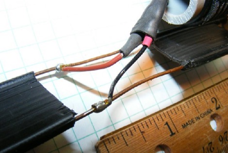
 An homebrew HF Magnetic loop made with 2m length of 6mm diameter copper pipe formed into a near circle as the low loss inductor, a short length of coax as a capacitor,a short length of mains cable, again as a fixed tuned capacitor, a tunable 365pF air spaced capacitor, and a small Jackson C804 airspaced variable with a small 3-35pF trimmer in parallel