Search results
Query: base antennas
Links: 145 | Categories: 2
-
 Scan Antenna supply precision antennas to some of the world’s most advanced, market leading companies. Their antennas fit in satellite voice/data, mobile/wireless GSM, GPS, marine/land based radio and other specialty systems.
 -
 On-line shop for coax cables, RF connectors, Lightning protectors, Create antenna rotators, antenna masts and mounts, amateur antennas by FlexaYagi, Tonna F9FT, ANjo-Antennen and M2 Antennas based in Eggolsheim Germany
 -
 Antennas for the 1296 MHz based on the construction plans of some Yagis 35 elements by DL6WU, F9FT, DJ9YW. These antennas features a boom of about 3 m and gives a gain of about 17.8 dBd
 -
 A quarter wave vertical omni-directional antenna for 7 MHz. Formulas for dimensions in feet and meters are provided. Ideal radial angle is between 35° and 45°. Velocity factor (Vf) varies based on coax type.
 -
 High Speed Multimedia (HSMM) radio, as introduced by John Champa, K8OCL, represents a significant advancement in amateur radio's digital capabilities, moving beyond traditional keyboard modes like packet radio. This initiative, driven by ARRL's Technology Task Force, focuses on developing high-speed digital radio networks capable of up to 20 megabits per second. HSMM primarily facilitates digital voice (DV) and digital video (ADV), enabling real-time video transmission from emergency scenes to an EOC without expensive ATV gear, often requiring only a laptop, a PCMCIA card, a digital camera, and a small antenna. The working group's initial efforts concentrate on cultivating microwave skills within the amateur community to build and support portable and fixed high-speed radio-based local networking, or **RLANs**. These networks prove invaluable for RACES and ARES organizations, as well as homeland security and other emergency communications. Field Day exercises and simulated emergency tests (SETs) are encouraged to hone skills in rapid site surveys and deploying broadband HSMM microwave radio networks, with examples like linking Field Day logging stations or antenna test results at the Midwest VHF-UHF Society Picnic 2003. Getting started with HSMM often involves adapting off-the-shelf **IEEE 802.11** (WiFi) equipment to comply with amateur radio regulations, typically operating in the 2.4 GHz ISM bands. While consumer WiFi gear has range limitations under Part 15 rules, proper setup under amateur regulations can extend coverage significantly, with test networks like the Hinternet achieving 5-15 mile ranges at 54 M bit/s using small mast-mounted dish antennas. Careful selection of equipment with external antenna ports, high transmit power, and low receive sensitivity is crucial, along with using low-loss coaxial cable like LMR-400 for optimal performance at these frequencies.
 -
 Voldatech, a manufacturer based in China, produces a range of RF feeder cables and site components essential for amateur radio installations and telecommunication infrastructure. Their product line includes various types of coaxial cables, such as **50 Ohm** and 75 Ohm options, along with a comprehensive selection of connectors like N-type, UHF, and BNC. These components are critical for maintaining signal integrity and minimizing loss in antenna systems, whether for a home shack or a remote DXpedition setup. The company's focus on _RF Coax cables_ and connectors directly supports the needs of radio amateurs seeking reliable transmission lines for their transceivers and antennas. Amateurs often compare Voldatech's offerings to established brands, evaluating factors such as impedance matching, shielding effectiveness, and durability under various environmental conditions. The availability of diverse cable types allows operators to select optimal solutions for different frequency bands and power levels, from QRP to high-power amplifier setups. Their products are particularly relevant for those constructing new antenna arrays or upgrading existing feedline systems, aiming to achieve maximum power transfer and reduce standing wave ratio (SWR) for efficient signal propagation.
 -
 10 Elements Cross-Yagi Antenna for 433 MHz. The base of the 10el antenna is the recalculated RA6FOO antenna.Circular polarization is realized - by a phasing quarter-wave line, matching of horizontal and vertical polarization antennas
 -
 Operating in antenna-restricted communities presents unique challenges for amateur radio operators, often necessitating creative solutions for antenna deployment. This resource details the design and implementation of stealth antennas within a townhouse community in Exton, PA, where external antennas were strictly forbidden by covenants. The author, WB5NHL, describes his setup, which involved locating the shack in the basement and utilizing an unused space under the roofline of a finished third-floor loft for antenna placement. The content specifically addresses the practicalities of routing coax cables three floors and maximizing antenna performance within limited attic space. It covers solutions for multi-band operation, including dedicated sections for 40-10 meter and 80-meter antennas, along with strategies for mitigating potential interference issues. The approach emphasizes full compliance with community covenants, achieving maximum height-above-ground for horizontal antennas, enabling instant band switching, and efficiently utilizing available attic volume. While acknowledging limitations such as potential interference with high power and fixed antenna patterns, the resource provides a detailed account of a functional compromise for restricted environments. Links to individual pages on _coax cables_, _40-10 meter antennas_, _80-meter antennas_, and _interference issues_ offer deeper dives into each specific aspect of the installation.
 -
 A hexagonal beam is a form of the Yagi antenna which is based on parasitic principles developed early in the last century in Japan for achieving gain in one direction.How HexBeam antennas works. A hexagonal beam operates exactly like Yagi antenna, but instead of a driven element that is straight like a dipole, it is a wire bent into the shape of the letter M.
 -
 The PAC-12 Antenna, a multi-band portable vertical, is meticulously detailed in this construction article by James Bennett, _KA5DVS_. The design emphasizes ease of homebrewing using readily available components from local hardware stores, including replaceable loading coils. It outlines the preparation of the 72-inch telescoping whip (originally from Radio Shack, with an alternate source now provided by _Pacific Antenna_), the construction of the loading coils from PVC risers, and the fabrication of the aluminum rod base sections. Specific instructions cover threading aluminum rod with a _1/4-20 threading die_ and assembling the feedpoint insulator with a BNC connector, along with recommendations for radial deployment. KA5DVS, an avid traveler and QRP enthusiast, developed the PAC-12 to address the bulkiness of random wire setups and the limitations of commercial portable antennas like the Outbacker or SuperAntennas MP1. His goal was a lightweight, packable antenna that disassembles into 12-inch sections, achieving an assembled length of approximately 8 feet. The design strategically places the loading coil away from the base for improved efficiency. The PAC-12 notably placed first in efficiency compared to a quarter-wavelength wire vertical at the HFPack antenna shootout during the Pacificon conference in October 2001, demonstrating its practical performance for field operations. Appendix C showcases various _NJQRP Club_ members' PAC-12 constructions, including a 20m beam made with multiple PAC-12 elements.
 -
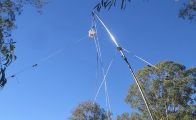
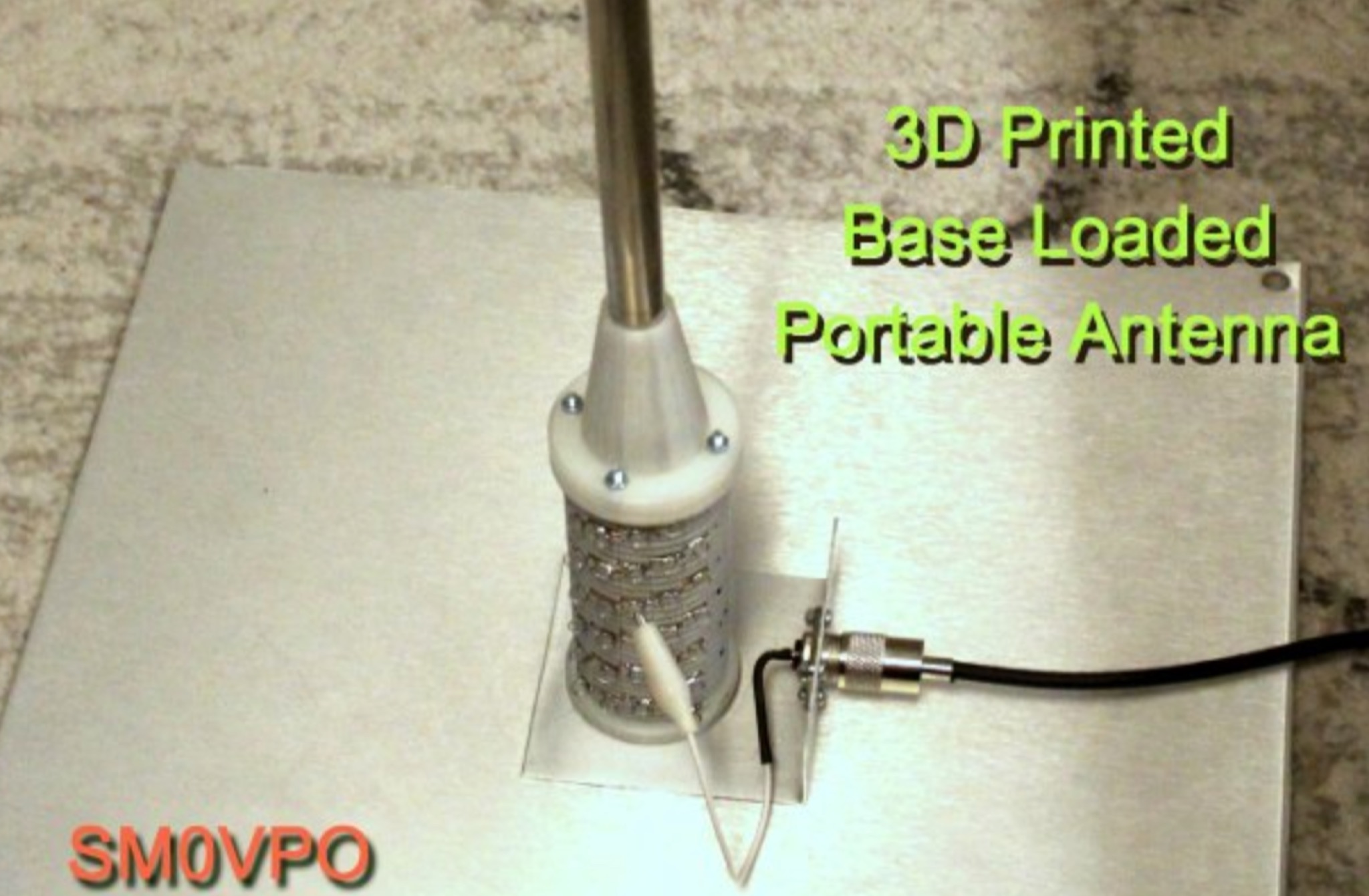
 This article shares the author's experience with building antennas. After putting a large magnetic loop project on hold, they decided to try a base-loaded vertical antenna. The author explains how they chose to design a new antenna from scratch, aiming for a frequency of 7 MHz. They describe the calculations needed to find the right coil inductance and how they used 3D-printed parts for the construction. The article wraps up with results from their initial tests, showing good communication on different bands and highlighting the success of their design.
 -
 The _G3TSO_ Mobile Antenna Page details construction and tuning methods for mobile antennas operating across **10 to 160 metres**. The content describes a Hustler-based design, optimized for RF performance and vehicle speeds, featuring centre loading. For optimal operation on various bands, the loading coil placement requires clearance from the vehicle body. Antenna resonance is critical for efficient mobile operation. A mobile antenna's base impedance may be as low as 27 ohms, requiring specific matching to achieve maximum radiation, as a minimum SWR at the transmitter does not always indicate resonance or maximum output. Tuning involves physical adjustment of antenna length to achieve resonance at the operating frequency. The _G3TSO_ page outlines a tuning procedure utilizing a low-power signal source and a field strength meter to identify maximum radiation before impedance matching. Loading coil placement, either at the base, center, or top of the antenna, influences radiation efficiency and mechanical stability for mobile installations. Centre-loaded whips, such as the Hustler design, offer a compromise between efficiency and stability, often for single-band operation. Helically wound antennas, including those for **28 MHz**, may present base impedances around 17 ohms, resulting in a 3:1 SWR at resonance. Low resistance grounding at the antenna base is also specified for optimizing performance and minimizing RFI during mobile operation. DXZone Focus: Mobile | Any | Antenna Tuning | HF
 -
 Article on portable HF antenna where author diverge about antenna efficiency versus size based on his personal experience on using HF antennas during portable operations
 -
 This is a remote antenna switch I use in my attic to connect transceivers in the basement to multiple antennas in the attic. The goal of this project is to be able to remotely connect one of the antennas in the attic to the only antenna cable available.
 -
 The HB9CV antenna calculator aids amateur radio enthusiasts in designing antennas for VHF and UHF bands. By inputting the working frequency, users can obtain crucial dimensions like dipole lengths and distances. The tool, based on the HFSS antenna model, provides data on impedance, VSWR, and gain, optimizing front/back radiation ratios. It includes tips for fine-tuning using a Г-matching balun and compensating capacitor, ensuring effective performance and minimal VSWR for enhanced radio communications and direction finding.
 -
 Operating within the low-frequency spectrum, transformers serve critical roles in antenna systems, particularly for 160m applications. The resource details the construction and performance of 1:1 transformers built on BN-73-202 cores, emphasizing their use as hybrid combiners or phase inverters for RX antenna arrays. Measurements reveal that these transformers exhibit minimal losses, around 0.12 dB at 1.8 MHz, with variations based on wire type and number of turns. The analysis includes comparative data on transformer performance, highlighting the impact of different winding techniques on frequency response. Notably, the use of coaxial cable for winding improves bandwidth while maintaining low-frequency efficiency. The resource also discusses braid breaker transformers, which minimize inter-winding capacitance, achieving low losses around 0.21 dB at 1.8 MHz. These insights are crucial for optimizing low-band antenna systems, allowing operators to make informed decisions regarding transformer design and implementation.
 -
 The 80-meter Skyloop antenna, a top-performing HF antenna, excels in weak signal work, low-noise operation, and omnidirectional coverage. Ideal for fixed stations, it delivers strong performance at low power, outperforming many alternatives, including 80m half-wave end-fed antennas. Requiring significant space for deployment, it’s well-suited for NVIS and groundwave use. Though not portable, it’s cost-effective and durable, with minor maintenance needs. Tuning may require adjustments for optimal resonance. It’s a standout for base stations, though a lighter portable version could enhance its versatility.
 -
 Ham Radio Dealer based in Holland dealers of most relevant ham radio brands. Transceivers, antennas and accessories for amateur radio and marine radio markets.
 -
 Learn how to design and analyze a folded trifilar antenna for the 80-meter band. Based on a description from RAF antennas between 1940 and 1970, this article provides step-by-step guidance on modeling the antenna, calculating resonance frequency, adjusting dimensions, and verifying performance. Perfect for hams looking to improve their antenna setup for better transmission and reception on the 80M band.
 -
 This is very common W7IUV Flag Antenna design is based on the PY3AGD antenna because it uses the antenna mounted horizontally and nd it is perfect for my small city lot installation.
 -
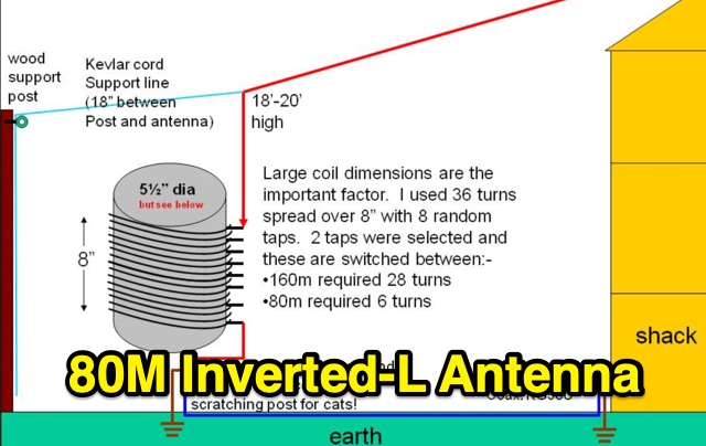 80m Inverted-L Antenna, Base-loaded for 160m antenna. This antenna is not a good DX antenna however within small garden where true DX antennas would be impossible it has performed very well.
 -
 Amateur Radio goodies for not only the Shack, but also a range of outdoor/portable kit. Ferrite toroids, RTL SDR, Un-uns and Baluns for antennas and RF Filters. Based in the UK.
 -
 Amateur radio antenna manufacturer, HF VHF UHF antennas, and amateur radio accessories dealer based in Lingen Germany
 -
 The J-pole antenna calculator helps users design custom J-pole antennas for specific frequency bands. It provides dimensions for key antenna sections based on the chosen frequency and material’s velocity factor. The calculator also offers insights into J-pole antenna mechanics, velocity factors, and mounting tips, making it ideal for enthusiasts creating antennas for amateur or mobile radio communications.
 -
 This study details a reception comparison between vertical and horizontal active loop antennas, specifically two identical _Wellgood active loop antennas_, on various HF bands. The experiment, conducted in a densely populated QRM-prone area, monitored FT8 signals over a 24-hour period using two identical receivers. The methodology involved direct comparison of signal reception across the HF spectrum, aiming to identify performance differences based on antenna orientation. The results indicate that vertical loops demonstrated superior performance on higher bands (10m, 15m, 20m), while horizontal loops excelled on lower bands (30m, 40m, 160m), particularly for receiving long-distance (DX) signals. The horizontal loop's advantage on lower bands is attributed to potentially better low-angle performance and reduced sensitivity to man-made noise, yielding a **2-3 S-unit** improvement on 160m. The study provides practical insights for optimizing antenna placement in challenging urban environments, noting that the horizontal loop consistently showed a **10-15 dB** signal-to-noise ratio improvement on lower bands.
 -
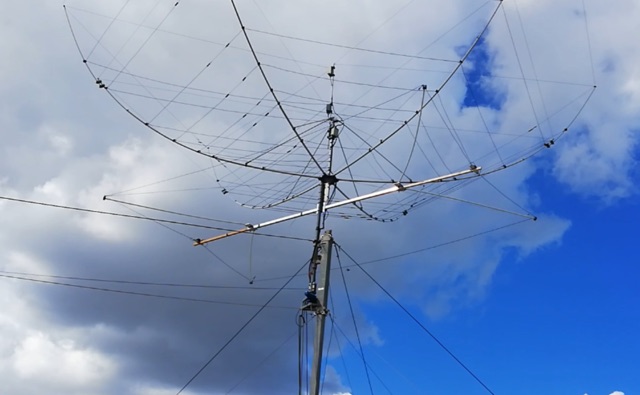
 This Satellite Antenna Elevation System project involves mounting horizontally polarized Yagi antennas on a fiberglass reinforced polymer (FRP) crossboom. A Yaesu G-800DXA azimuth rotator is in place, requiring only an elevation rotation system. Elevation is controlled by a 12VDC linear actuator connected to a U-bolted arm on the crossboom, rotating within a DIY bearing arrangement. Common handyman tools suffice for assembly. The setup includes FRP crossboom, aluminum tubing, PVC couplers, nylon camshaft bushes, and a K3NG-based controller for azimuth and elevation control. Detailed guides and resources are available online.
 -
 7MHz to 30MHz operation is achieved with a magnetic-mounted HF antenna designed for car roof deployment, capable of handling 100 Watts without an external antenna tuner. The design incorporates a large base-loading coil with multiple taps, allowing for frequency selection across various HF bands. This coil effectively increases the electrical length of a short telescopic antenna element, compensating for its inherent capacitance. Construction involves 3D-printed components for the coil former and support structures, though conventional building methods using plastic drainpipes are also suggested. The car body serves as the ground plane, with the coil assembly mounted on a 500mm square metal plate secured by super neodymium magnets. Protection under the magnets is advised to prevent vehicle scratches. Detailed instructions cover winding the 30-turn coil with 2.5mm diameter household electrical cable, assembling the 3D-printed parts, and making soldered connections. Taps are staggered every five turns for precise frequency adjustment. Performance examples include a 7913km contact to Japan using a 1.5m element and 100 Watts, demonstrating low-angle radiation and omni-directional pattern with minimal S-point loss compared to a full quarter-wave.
 -
 This page allows hams to design a vertical-plane delta-loop antenna for a single amateur HF band in different configurations. By choosing different feed-point positions, operators can observe variations in polarization properties, radiation patterns, and feed-point impedances. Users can generate radiation pattern plots, VSWR charts, antenna current diagrams, and Smith charts for their antennas over various ground types. Through adjusting the antenna's physical dimensions and refreshing the plots, hams can gain insights into the antenna's performance in the field. The page also discusses how elevation radiation patterns may change based on the antenna configuration and feed-point position.
 -
 A vertical delta loop is a practical antenna for low bands, popular for its simple design requiring just one support. Its shape, an equilateral triangle in free space, yields optimal gain and radiation resistance. Deviating from this shape lowers performance. The delta loop can be polarized either horizontally or vertically based on the feed point location. In vertical polarization, it acts as two quarter-wave verticals with the baseline feeding one side. This design minimizes radiation from the baseline while maintaining effective operation.
 -
 The PA0FRI Unbalanced/Balanced ATU is a home-built antenna tuner designed to efficiently match a W8JK 2-element beam antenna fed with a 450-ohm twin lead. Based on PA0FRI’s S-Match design, it optimizes energy transfer while maintaining balance, reducing losses, and ensuring proper radiation. The tuner uses a roller inductor, air variable capacitors, and a T200 iron powder coil, allowing fine-tuning across 14-50 MHz. Extensive lab tests confirm minimal attenuation and precise impedance matching, making it a reliable and efficient ATU for balanced antennas.
 -
 Learn how to choose the right portable antennas for backpacking as a ham radio operator. Find out the factors to consider, including weight, performance, and reliability. Understand the trade-offs involved in selecting the best antenna for your needs, based on the purpose of your trip and distance to be covered. Discover different options available and how they can help you make contacts while on the go. Get insights into one ham radio operator's portable antenna kit and the factors that influenced their choices. Explore the importance of band selection and adaptability in creating a successful antenna system for backpacking adventures.
 -
 Demonstrates the construction and portable deployment of a 40-meter horizontal loop antenna, often referred to as a "Sky Loop" or "DX-Buster." The design adapts a full-wavelength horizontal loop for field use, eliminating the need for traditional insulators by employing four 5-meter heavy-duty _squid poles_ and metal post bases for support. This setup facilitates rapid assembly, crucial for portable operations, with the antenna wire length specified at approximately 43-45 meters for optimal 40-meter band performance. The resource details the specific construction methodology, including winding the antenna wire around rubber caps on the squid poles and securing it with electrical tape. It provides a parts list and assembly techniques, focusing on minimizing components for ease of transport and quick setup. The article, originally published in the February 2013 edition of the Central Coast ARC "Smoke Signals" magazine, reflects practical experience. This documentation offers a field-deployable 40-meter loop antenna solution, utilizing readily available components like fiberglass squid poles. It presents a practical approach for operators seeking a robust, portable antenna for the 40-meter band, emphasizing simplicity and efficiency in its design and deployment.
 -
 Medium power BMU (Base Matching Unit) intended for 42 foot to 48 foot vertical, sloper, or Inverted-L antennas.
 -
 The Beverage on Ground (BOG) antenna offers ham radio operators a compact alternative to traditional Beverage antennas, requiring less space and fewer support structures. This implementation, optimized for 1.8-7 MHz bands, describes ideal parameters: lengths of 60-90 meters, height of 2-10 cm above ground, and specific load resistances based on configuration. The article details experimental methods for determining optimal load resistance and presents matching systems to convert BOG impedance to 50 ohms. While less effective than classic 200-300 meter Beverages, the BOG provides directional reception in limited space, though performance varies with ground conditions and weather changes.
 -
 The resource details the construction of a 433 MHz LoRa APRS iGate and a tracker, both built around _TTGO T-Beam v1.1_ microcontroller boards. Each board integrates an OLED screen, WiFi, GPS, and an SMA antenna connector, powered by an 18650 3.7 V lithium-ion battery or microUSB. The iGate operates on 433.775 MHz, with its status verifiable on aprs.fi, demonstrating practical implementation of LoRa-based APRS solutions. The methodology involves programming the modules using Visual Studio Code with the PlatformIO plugin. This process loads the necessary firmware and a JSON configuration file, which includes the operator's callsign and WiFi credentials for the iGate. The guide emphasizes the ease of programming and provides specific steps for configuration. Initial testing of the iGate and tracker, including smart beaconing configuration, is documented. The low power output of approximately 200 mW from the LoRa board's transmitter is noted, with suggestions for range extension through improved antennas or RF amplification. The author, N4MI, plans to deploy a higher-gain 70cm antenna for the iGate.
 -
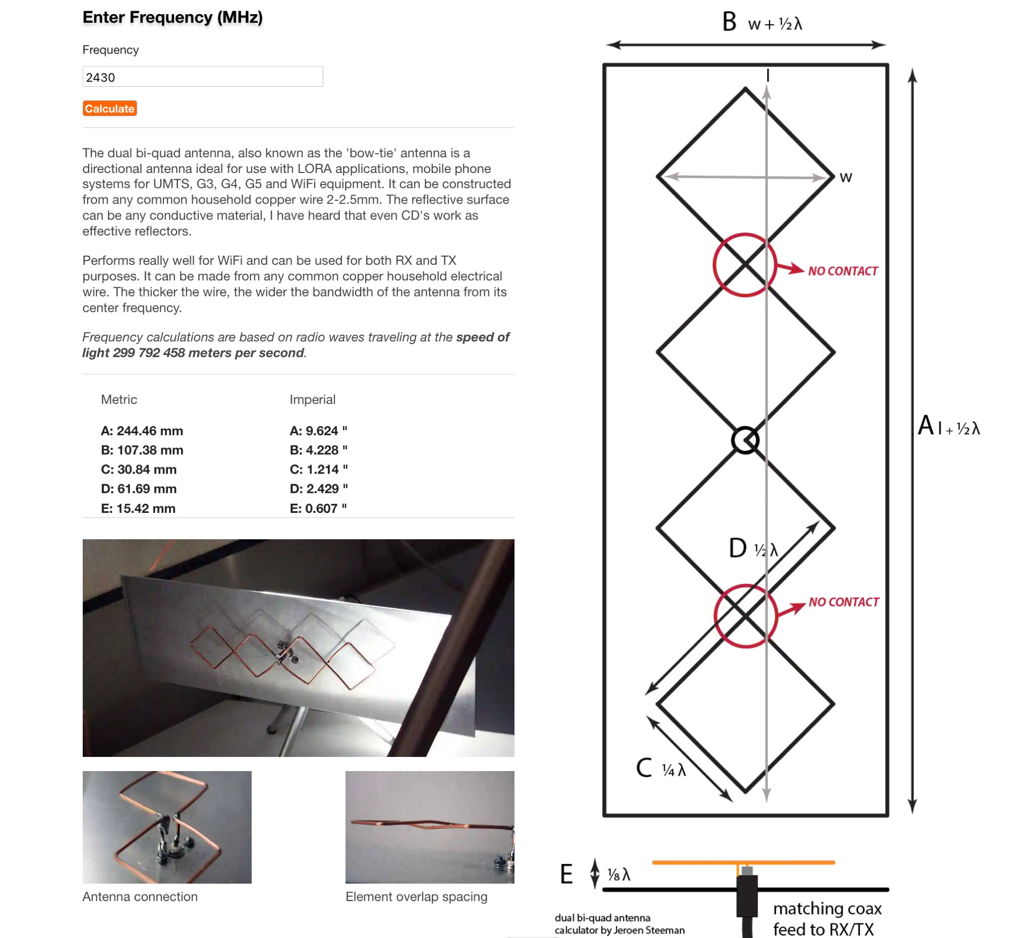 This webpage offers an online antenna designer tool to calculate the dimensions for constructing a double bi-quad antenna for various frequencies. The directional antenna is suitable for UHF and higher frequencies, such as WiFi, UMTS, LORA, and mobile phone networks. It provides dimensions based on the input frequency, making it ideal for hams looking to build their own antennas for specific applications. The tool also mentions using common household materials like copper wire for construction, making it accessible for amateur radio operators with basic equipment.
 -
 Fully functional weathervane conceals an efficient 2- meter base-station antenna. Your Neighbors and HOA won’t know it’s there and they will love the rooster-vane. The Rooster-Tenna is a covert 2-meter ham radio antenna disguised as a functional weathervane, ensuring seamless integration into residential environments. This improved version features a wide-spaced parallel-fed folded dipole in a compact skeleton slot design. Constructed from aluminum tubing and acrylic supports, it offers omnidirectional, vertically polarized performance suitable for repeater and satellite use. Easy to mount and tune, it achieves a low SWR across the 2m band. With 3D-printable parts available, the Rooster-Tenna blends practicality with stealth, making it an ideal solution for HOA-restricted areas
 -
 YAGio 1.01 is a Windows-based software for designing DL6WU long Yagi antennas on VHF and UHF frequencies. It supports Windows 2000, XP, Vista, 7, and likely 8. Using keyboard commands, users input specifications such as frequency, gain, and element diameters, and YAGio generates the design. You can download latest Yagio version from this page. Results can be saved in YIO, NEC, YAG, MMA, and YC6 formats, or printed directly.
 -
 Details the construction and performance of a phase-controlled receiving array, specifically a **MicroSWA** variant, optimized for QRP low band fox hunting on 40M and 80M. The resource documents the author's iterative design process, addressing significant regional noise challenges encountered during 0100-0230 UTC fox hunt periods. Initial experiments involved a director wire on a 40M vertical, yielding limited improvement, prompting a shift towards advanced null-steering techniques. The project leverages concepts from Victor Misek’s "The Beverage Antenna Handbook" and Dallas Lankford’s extensive work on phased receiving antennas for urban lots. A key modification involved integrating a new passive phase control box and a push-pull **Norton common base preamp** using 2N5109 transistors, designed for high third-order intercept performance to maintain weak signal integrity amidst strong adjacent signals. The system incorporates Faraday-shielded transformers with RG174 primaries on -75 ferrite cores, housed in ABS plastic pipe. Performance tests confirmed the MicroSWA's ability to produce deep, steerable nulls, achieving approximately 30 dB noise reduction on 160M, 80M, and 40M. This enabled detection of QRP signals undetectable on conventional transmit antennas. The final unit includes front panel controls, a 10-11 dB preamp, and a robust power conditioner, demonstrating effective noise mitigation for challenging low band QRP operations.
 -
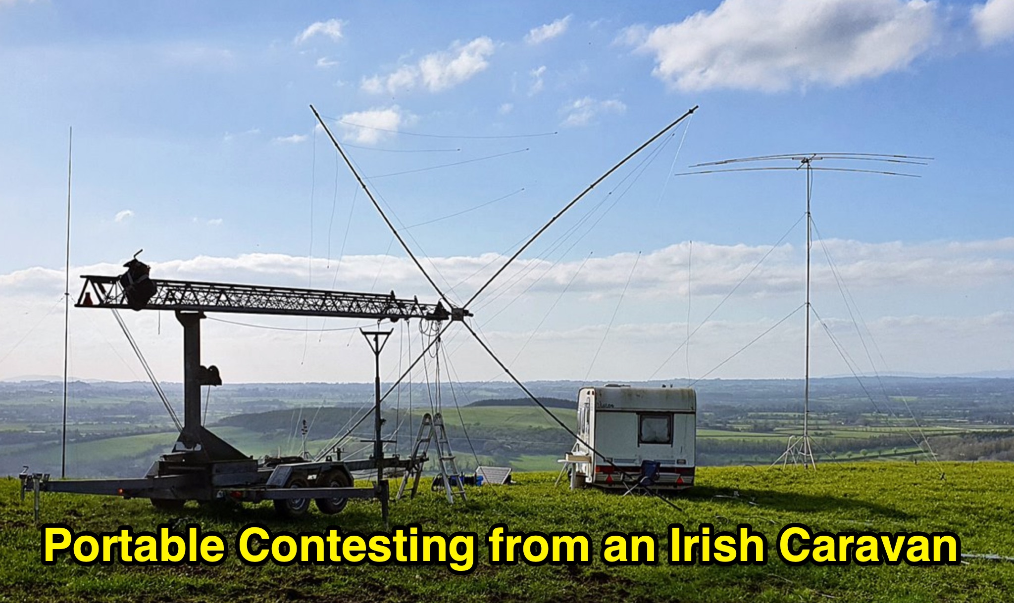 This blog chronicles over a decade of portable HF contesting from rural Ireland (2008–2019) by Olivier, operating under callsigns EI/ON4EI, EI8GQB, EI1A, and EI7T. Using only green energy from a caravan, he achieved top-tier results in major international contests—including 1st World in the 2018 IARU HF Championship (SSB LP) and multiple 1st-place finishes in CQ WW and CQ WPX SSB Europe. Operating in the demanding Single Operator All Band Low Power and SO2R categories, he deployed up to five antennas across five bands, often in remote or emergency-style conditions. The narrative blends technical detail, fieldcraft, and personal reflection, documenting triumphs, setbacks (including carbon monoxide poisoning), and the logistical challenges of sustainable portable operation—culminating in his decision to transition to team-based contesting and future DXpeditions.
 -
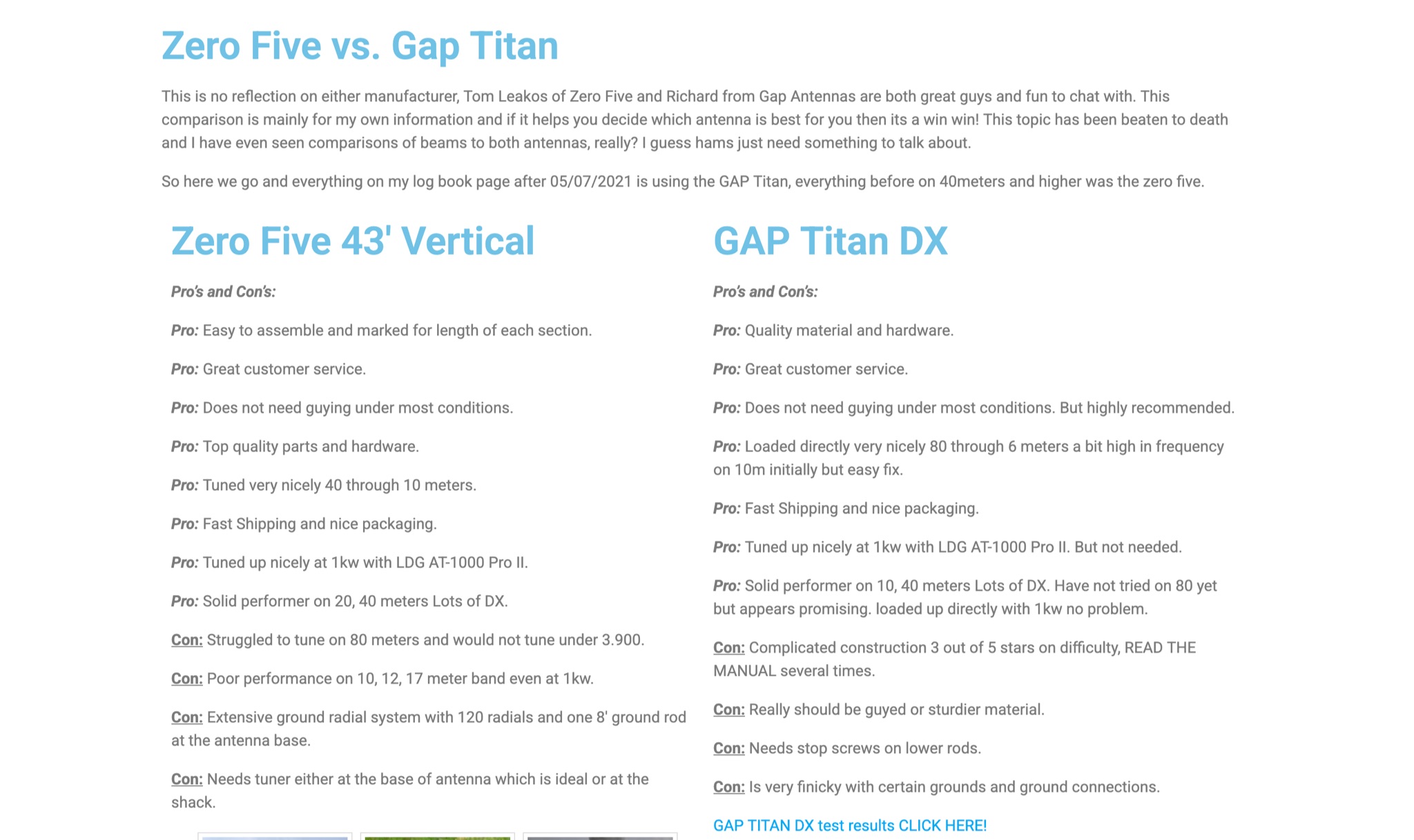 This page provides a detailed comparison between the Zero Five and Gap Titan ham radio antennas. The author shares their personal experience with both antennas, highlighting pros and cons for each. They discuss aspects such as ease of assembly, customer service, tuning capabilities, performance on different bands, and the need for grounding and tuning. The comparison aims to help readers make an informed decision on choosing the best antenna for their needs, based on real-world usage scenarios and feedback.
 -
 This page offers an online tool to calculate the dimensions for a quarter wave antenna based on a specified frequency. It helps hams design antennas for optimal reception and transmission properties, using 1/4 wavelength elements. The calculator ensures a matching impedance of 50 Ohm without the need for additional components. The page is useful for amateur radio operators looking to build efficient antennas for their radio communication setup.
 -
 The article describes adding lightning protection to Beverage antennas, which are long wires susceptible to lightning strikes. The author reviews common lightning protection circuits and discusses their components. They then detail their design based on existing methods, highlighting choices for components and reasoning behind them. Finally, the author presents the completed design and its implementation on their Beverage antennas.
 -
 SAT filters ensure effective full-duplex satellite QSOs by mitigating interference between 145 MHz uplink and 435 MHz downlink signals. Custom coaxial and SMD-based filters address transmitter harmonic interference and improve receiver isolation, achieving over 70 dB suppression in the undesired band. Designed for simplicity, these filters maintain optimal VSWR and are housed in shielded brass enclosures. Practical implementations with Yagi antennas demonstrate compatibility with SDR systems, enabling seamless communication even in challenging satellite conditions, such as low-elevation passes and DX pile-ups.
 -
 This page provides a detailed example of the modeling and analysis of an 80m delta dipole antenna with a 600-ohm bifilar feedline. The model is based on antennas used by the RAF from 1940 to 1970. It covers the original model specifications, conductor mass calculations, resonance frequency observation, geometry adjustment steps, and final antenna dimensions. The content includes theoretical formulas, resonance frequency calculations, and practical steps for adjusting the antenna for optimal performance. Overall, it serves as a practical guide for hams looking to understand and optimize the performance of a delta dipole antenna for the 80m band.