Search results
Query: horizontal
Links: 137 | Categories: 0
-
 The Bazooka antenna, a coaxial dipole, functions as an omnidirectional antenna with vertical or horizontal polarization. Patented in 1939 and refined in 2006, it features a quarter-wavelength coaxial cable with separated conductors. The outer conductor connects to a sleeve, while the inner conductor extends vertically. Initially complex, it has been simplified for versatile use, including military applications. Adding elements can modify its behavior for NVIS or Yagi-Uda configurations. Experiments in 2007 at the Campus de Pesquisas GeofÃsicas in Paula Freitas-PR demonstrated consistent VHF and UHF performance, showing reliable return loss measurements despite variable weather.
 -
 An omnidirectional horizontal polarization antenna for 2 meters band in Italian
 -
 The page automatically generate a Great Circle Map (GCM) for ham radio operators based on the IP address or by a given QTH locator. The GCM generated, unlike traditional maps of this type, has been rendered in an elliptical shape instead of a circle. This provides an expanded view horizontally thus making it easier to interpret. The map base is colored with each continent colored differently for easier recognition. The color code of the continents is given below the map for easy reference
 -
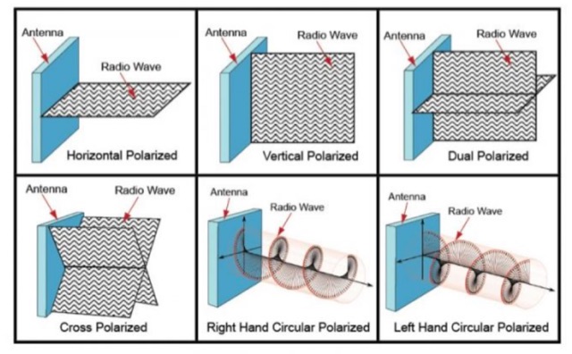 What is antenna polarization, and why does it matter. Horizontal versus Vertical versus Circular polarization. Undestanding how antennas perform better with different polarizations.
 -
 This page presents an online calculator tool for determining the dimensions of various HF wire antennas operating between 1.8-30 MHz. Users input their desired resonant frequency to obtain precise measurements for four popular antenna types: standard flat-top dipole, inverted Vee, quad loop, and equilateral delta loop. The calculator provides comprehensive measurements including leg lengths, minimum heights, horizontal spreads, and feedpoint distances. Accompanying the calculator are detailed technical explanations, construction notes, and installation guidelines for each antenna type, making it a practical resource for amateur radio operators building their own antennas.
 -
 An Inverted-L with its long leg sloping to the ground. It will still work very good, even if the horizontal wire has to be sloped diagonally to the ground, as long as you have enough horizontal space to keep it at about a 45 degree angle or more from the pole.
 -
 A coaxial cable trap is a fundamental component in multiband antenna design, enabling a single radiator to resonate efficiently on multiple frequencies by electrically shortening or lengthening the antenna element. This project focuses on constructing such a trap for a vertical antenna operating on the 10 MHz (30m) and 14 MHz (20m) amateur bands, providing practical insights into its fabrication and integration. The article outlines the specific dimensions and winding techniques for the coaxial trap, emphasizing the use of readily available materials. It details the physical construction of the vertical element, including the mast and radiating sections, to achieve optimal performance across both target bands. The author shares personal experiences with similar trap designs, noting their effectiveness in previous horizontal dipole configurations. Key construction steps are illustrated with _original photos_, showing the assembly of the trap and its incorporation into the overall antenna structure. The design aims for a compact footprint, making it suitable for limited space installations while still delivering effective DX capabilities on the **30-meter** and **20-meter** bands.
 -
 This is very common W7IUV Flag Antenna design is based on the PY3AGD antenna because it uses the antenna mounted horizontally and nd it is perfect for my small city lot installation.
 -
 WB8LZR details the construction and initial field results of a multi-band vertical wire antenna, designed to complement his existing horizontal loop for improved DX on 80 meters. The antenna utilizes a 67-foot vertical wire, configured as a quarter-wave radiator on 80m, and employs a 1:1 current balun for RF isolation on 80m, 30m, and 17m. For bands like 40m, 20m, and 10m, where the wire acts as a half-wave or full-wave radiator, an additional impedance transforming _unun_ is integrated to manage the significantly higher feedpoint impedance and voltage. The author notes the vertical's performance as a receiving antenna, observing reduced noise compared to his main horizontal loop, particularly on 80m, and even hearing some long-path signals the loop missed. Initial QRP contacts, including a **1-watt** QSO with a _VP2 station_ on 30m, demonstrate its transmit capability. While the radial system is currently rudimentary, the project outlines practical considerations for multi-band vertical deployment and impedance matching.
 -
 This project explores the construction and performance of an Alford Loop antenna as an alternative to a round loop. The Alford Loop, symmetrically fed at opposite corners, behaves like a small loop despite its larger size. Built using PVC pipes and secured with tire wraps, the antenna integrates an LZ1AQ active amplifier for optimal performance. With deep nulls in its horizontal radiation pattern and improved resonance characteristics, this design has significantly outperformed previous active antennas in reception quality.
 -
 This project details the construction of a compact, circularly polarized Quadrifilar Helix Antenna (QHA) designed for 146 MHz operation. The antenna features a 1/2λ1/2λ helical design with a 2.6:1 aspect ratio, providing 4.5 dB gain and a spheroid radiation pattern. It is ground plane independent and compatible with both vertical and horizontal polarizations, making it ideal for terrestrial and space communications. The design includes step-by-step instructions for building the antenna using readily available materials like aluminum rods, PVC pipes, and RG-58 coaxial cable. The antenna's performance has been validated through comparisons with commercial omnidirectional antennas, showing superior results.
 -
 This study details a reception comparison between vertical and horizontal active loop antennas, specifically two identical _Wellgood active loop antennas_, on various HF bands. The experiment, conducted in a densely populated QRM-prone area, monitored FT8 signals over a 24-hour period using two identical receivers. The methodology involved direct comparison of signal reception across the HF spectrum, aiming to identify performance differences based on antenna orientation. The results indicate that vertical loops demonstrated superior performance on higher bands (10m, 15m, 20m), while horizontal loops excelled on lower bands (30m, 40m, 160m), particularly for receiving long-distance (DX) signals. The horizontal loop's advantage on lower bands is attributed to potentially better low-angle performance and reduced sensitivity to man-made noise, yielding a **2-3 S-unit** improvement on 160m. The study provides practical insights for optimizing antenna placement in challenging urban environments, noting that the horizontal loop consistently showed a **10-15 dB** signal-to-noise ratio improvement on lower bands.
 -
 This Satellite Antenna Elevation System project involves mounting horizontally polarized Yagi antennas on a fiberglass reinforced polymer (FRP) crossboom. A Yaesu G-800DXA azimuth rotator is in place, requiring only an elevation rotation system. Elevation is controlled by a 12VDC linear actuator connected to a U-bolted arm on the crossboom, rotating within a DIY bearing arrangement. Common handyman tools suffice for assembly. The setup includes FRP crossboom, aluminum tubing, PVC couplers, nylon camshaft bushes, and a K3NG-based controller for azimuth and elevation control. Detailed guides and resources are available online.
 -
 An cheap and efficient wire antenna for lower HF bands. This closed loop antenna, radiates perpendicular to its plane with a bi-directional radiation pattern. With a gain of 2 dB over a diplole it is a low noise sensible antenna. Requires a tuner if you want to use as a multiband antenna.
 -
 The article describes the construction of a Lindenblad antenna, which is well-suited for receiving signals from low-orbiting weather satellites. The key points are: The Lindenblad antenna has an omnidirectional horizontal radiation pattern and is optimized for low to medium elevation angles, making it ideal for tracking passing satellites near the horizon. It is designed to receive circular polarization, which is common for weather satellite signals. The antenna is constructed using 4 folded dipole elements arranged on a cross-shaped frame. The necessary materials include a plastic junction box, PVC tubing, and aluminum rods to form the dipole elements. The article provides detailed instructions for preparing the components, assembling the dipoles, and connecting the feed lines to create the complete antenna. The completed antenna can be mounted on a vertical support, with the dipole elements angled at 30 degrees from horizontal, to optimize reception of the passing satellites. The author notes that the design was originally published in a now-defunct magazine, Meteo Satellite Inf", in 1993
 -
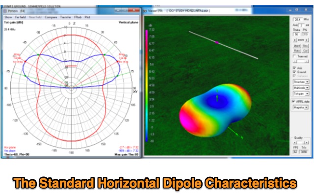 Discussion about the Standard Horizontal, Center-fed dipole and effects of elevation of the antenna on antenna radiation pattern.
 -
 Learn how to build wire Yagi antennas for your ham radio setup. Discover how smaller wire elements can offer practical and portable options for temporary operations. Explore designs like the Hex Beam, Spider Beam, and Moxon that require less mechanical complexity and can be easily rotated or supported. Find out how to construct and hang wire Yagis from ropes, trees, or masts with inverted vees or horizontal elements. Get tips on element positioning, gain, and beamwidth considerations. Follow simple construction steps using a rope boom and marking element positions for efficient assembly. Enhance your ham radio experience with versatile wire Yagi antennas.
 -
 A 10-meter half-wave vertical antenna, designed by Thomas 4L/G8BAG, offers a practical solution for hams with limited space and materials. This "flower pot" design utilizes common hardware store items such as 60mm plastic drain pipes and 75 Ohm coax cable, demonstrating that effective HF operation doesn't require specialized components. The author details the coax preparation, including stripping the outer sleeve and braid at specific measurements like **2510 mm** and 2450 mm, and integrating it into the pipe structure. The construction emphasizes simplicity and low cost, providing an accessible path to getting on the air on the 10m band, especially when a horizontal beam is not feasible. The article notes an SWR of _1.5:1_ with 75 Ohm coax, managed by an MFJ 258 for impedance matching. This temporary solution proved robust, withstanding various weather conditions and achieving contacts across continents, including W, VK, BG, G, JA, and VR2, using 100W SSB from Georgia.
 -
 Discover the success story of creating a 4-meter Delta Loop antenna, ideal for improving radio communication. This horizontally polarized antenna offers efficient performance when mounted at VHF heights, catering to both HF and VHF characteristics. A simple, DIY project suitable for portable setups, providing versatile options for radio enthusiasts.
 -
 Showcasing German engineering, ANjo Antennen develops and manufactures a diverse portfolio of amateur radio and commercial antenna products. Their offerings span a wide frequency range from 1.8 MHz to 3000 MHz, emphasizing electrical and mechanical precision for longevity. The company actively participates in events like FUNK.TAG Kassel, providing opportunities for direct engagement and order pickup. ANjo's product line includes high-performance **Yagi antennas** optimized for Tropo and EME, along with multi-stacked Quad antennas designed for contest operations, featuring wide horizontal and narrow vertical beamwidths. They also produce circularly polarized satellite antennas, some with switchable LHCP/RHCP, leveraging their commercial satellite antenna expertise. Beyond amateur applications, ANjo provides flexible, custom antenna solutions for commercial sectors such as BOS, EMC measurements, and telemetry. Their commitment to quality is evident in the Premium-Line antennas, which utilize **1.4301 (V2A) stainless steel** for mast clamps and connectors, ensuring durability and corrosion resistance. They also offer end-fed HF multiband wire antennas, known for their compact footprint and discreet installation.
 -
 For amateur radio operators engaging in portable operations like SOTA or POTA, rapid deployment of an effective antenna system is paramount. This video resource details the assembly process for the Buddipole multiband dipole antenna, showcasing its components and how they fit together. Rob, VK5SW, systematically presents the mast, coil arms, radiating elements, and the VersaTee hub, emphasizing the modular design that allows for quick configuration changes across various HF bands. The demonstration highlights the antenna's adaptability for different operating environments, from a ground-mounted vertical to a horizontal dipole. The video illustrates the ease with which the antenna can be packed and deployed, making it a practical choice for activations where setup time is limited. The Buddipole's design facilitates efficient band changes and tuning, crucial for maximizing QSO opportunities during field operations.
 -
 This is a 50 MHz WebSDR receiver, located in Ashford, CT, USA FN31VU using a deltaloop turnstile horizontally polarized omnidirectional antenna.
 -
 A vertical delta loop is a practical antenna for low bands, popular for its simple design requiring just one support. Its shape, an equilateral triangle in free space, yields optimal gain and radiation resistance. Deviating from this shape lowers performance. The delta loop can be polarized either horizontally or vertically based on the feed point location. In vertical polarization, it acts as two quarter-wave verticals with the baseline feeding one side. This design minimizes radiation from the baseline while maintaining effective operation.
 -
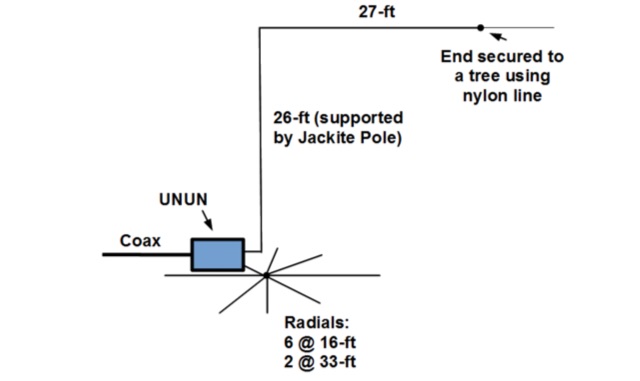 Inverted L antenna, even if not completely freestanding, it only requires one line to be lauched into a tree to support the end of the horizontal wire. This project is done with a 31-foot Jackite pole for a support and uses six 15-foot radials and one 33-foot radial.
 -
 Antenna patterns are all about interference. Presentation on wire antennas for HF bands. Dipoles, horizontal and vertical dipoles, effects of ground on radiation patterns, multi-band wires antennas. Knowing what you should expect from the radiation patterns for waves on your wires will help you choose what will work best for your needs. The principles of interference can lend insight into what to expect from a wire antenna.
 -
 Learn how to design a Hentenna antenna, a portable asymmetrical double-loop antenna ideal for amateur HF or VHF bands. This page provides details on constructing and optimizing the antenna for maximum performance in DX communications. Discover how altering the antenna's vertical feed section can adjust the VSWR resonant frequency and how changing the support pole's position can alter the beam direction. Originally developed by Japanese 6-meter operators, the 'Hentenna' offers a unique design that allows for horizontal polarization when vertically oriented. Explore radiation patterns, VSWR charts, and antenna currents diagrams to optimize your antenna's performance for long-distance contacts.
 -
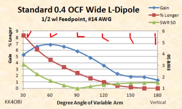 This page is a discussion about impedance matching by Off Center Fed dipoles in the Wide L-form. When a vertical or horizontal dipole is bent into a 90 degree L-form, the impedance drops about half.
 -
 Demonstrates the construction and portable deployment of a 40-meter horizontal loop antenna, often referred to as a "Sky Loop" or "DX-Buster." The design adapts a full-wavelength horizontal loop for field use, eliminating the need for traditional insulators by employing four 5-meter heavy-duty _squid poles_ and metal post bases for support. This setup facilitates rapid assembly, crucial for portable operations, with the antenna wire length specified at approximately 43-45 meters for optimal 40-meter band performance. The resource details the specific construction methodology, including winding the antenna wire around rubber caps on the squid poles and securing it with electrical tape. It provides a parts list and assembly techniques, focusing on minimizing components for ease of transport and quick setup. The article, originally published in the February 2013 edition of the Central Coast ARC "Smoke Signals" magazine, reflects practical experience. This documentation offers a field-deployable 40-meter loop antenna solution, utilizing readily available components like fiberglass squid poles. It presents a practical approach for operators seeking a robust, portable antenna for the 40-meter band, emphasizing simplicity and efficiency in its design and deployment.
 -
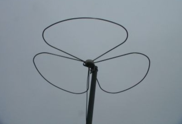
 Cloverleaf antenna is a circular polarized antenna which is way better than the cheap dipole antenna that comes with video transmitters and receivers. The Cloverleaf is a closed loop antenna which the signal and ground wires are connected. The cloverleaf antenna has 3 loops at 120 degree apart, and they are titled at 45 degree to horizontal plane.
 -
 The tri-band trapped delta loop antenna design operates on 80 meters (3.5–4 MHz), 40 meters (7–7.3 MHz), and 30 meters (10.1–10.15 MHz) using a single triangular wire loop. This configuration eliminates the need for an external antenna tuner or band-switching relays. The antenna's physical perimeter, approximately 270 feet, establishes 80M as the fundamental band, with specific trap placements enabling resonance on 40M and 30M. Trap design and placement are critical, with 30M traps positioned inboard of 40M traps within the horizontal element. Each slant leg measures approximately 80 feet. The resource references foundational information from the _ARRL Antenna Handbook_ and _ON4UN’s Low Band DXing_ regarding full-wave loop behavior and feedpoint impedances. The project aims to provide multi-band HF operation from a single, fixed antenna structure.
 -
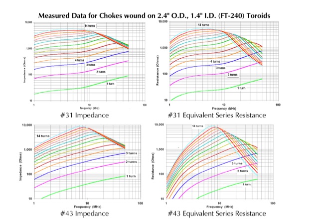 FT-240 toroids measurements. The data was measured using well-calibrated HP instrumentation. All plots have been adjusted to a frequency range of 1-100 MHz on the horizontal axis and a resistance/impedance range of 10-1,000 ohms on the vertical axis. This adjustment facilitates comparison among different materials and aids in determining their suitability for use on the HF ham bands.
 -
 The K5USS 6 Meter Hentenna Project page on Hamuniverse provides detailed instructions on how to build a 6 meter directional antenna with 3.5 dBd gain. The project is presented with permission from K5USS, Charlie of Richardson, Texas. This directional antenna is a full wave loop on 6 meters, horizontally polarized but mounted vertically, with a 50 ohm impedance, ideal for 6 meter SSB operations. The page is useful for hams looking to construct their own directional antenna for improved performance on the 6 meter band.
 -
 This project involved designing a 7-pole Chebychev broadcast band filter to address severe interference issues caused by a new horizontal loop antenna on the KN-Q7A transceiver. The interference overwhelmed the transceiver’s front end, so a custom filter with a 3.5 MHz cutoff was built using silver mica capacitors and type 6 T130 toroidal cores. Encased in a diecast box with SO239 sockets, the filter blocks strong signals from the broadcast band, achieving over 100 dB attenuation. Tested up to 100W, it reduces interference effectively while maintaining low insertion loss across HF bands.
 -
 This article details an Inverted-L antenna design optimized for 160-meter band operation, consisting of a 10m vertical section and a 28m horizontal section supported by Spiderpoles. Despite its relatively low height compared to the wavelength, the antenna has demonstrated impressive DX capabilities, achieving contacts up to 3,453 miles into Asiatic Russia. The system incorporates a Pi-Network ATU at the base for tuning flexibility. While modeling shows a radiation pattern favoring the South, practical operation indicates effective all-round coverage on Top Band.
 -
 Operating amateur radio satellites presents unique challenges, particularly concerning antenna design and signal propagation. Juan Antonio Fernández Montaña, EA4CYQ, recounts his three-year journey into satellite communication, starting with initial guidance from EB4DKA. His early experiments involved a portable 1/4 wave VHF antenna with four 1/4 wave ground planes, designed for hand-held use to adjust polarity. This setup, paired with an FT-3000M transceiver, allowed full-duplex operation on **VHF** transmit and **UHF** receive, proving effective for early contacts on satellites like AO27, UO14, and SO35. EA4CYQ's experience highlights the critical role of coaxial cable loss and antenna polarization. After encountering significant signal degradation with longer RG213 runs, he experimented with a 1/2 inch commercial cable, noting improved reception but persistent fading due to varying satellite polarities. This led to the construction of an **Eggbeater II** antenna, an omnidirectional UHF design offering horizontal polarization at the horizon and circular right polarization at higher elevation angles. Subsequent modifications resulted in the directional **TPM2** antenna, which provided sufficient gain for LEO satellites with a wide 30-degree lobe, enabling consistent contacts from his home station. The article concludes with practical insights on the performance of the Eggbeater II for both UHF and VHF, and the TPM2 for UHF, emphasizing their utility for portable and fixed operations. EA4CYQ's journey underscores the iterative process of antenna development and the importance of adapting designs to overcome real-world propagation challenges in satellite communications.
 -
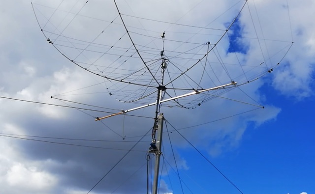
 This project describes a high-performance EME antenna array consisting of two home-designed 9-element Yagis, each about 2.5 wavelengths long, combined into a 25-ohm system and matched to 100 ohms using 9/4λ sections of 50-ohm coax. The array supports rotatable polarity from 0° to 180°, allowing both horizontal and vertical polarization to optimize moonbounce performance under varying conditions. Despite operating for years without a balun—something another designer called “disastrousâ€â€”the system has delivered strong results, including copying very weak DX such as VK3KH at about -25 dB with only 120 W (around 2 kW ERP). The builder continues to refine the mechanics, having installed new gear motors and an upgraded follow-up control system in 2011.
 -
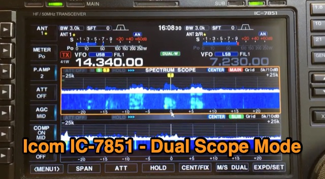 The Icom IC-7851 features the capability to display two scopes simultaneously, providing frequency, mode, and antenna information for each receiver. Users can choose between vertical or horizontal display orientations, and the dual scopes are also viewable on a high-resolution monitor connected to the radio. Additionally, the IC-7851 allows for mouse connectivity, enabling users to click on signals displayed on either scope for quick tuning. A demonstration video is available showcasing this dual scope functionality.