Search results
Query: beacon
Links: 233 | Categories: 11
Categories
- DX Resources > Beacons > 10 GHz Beacons
- DX Resources > Beacons > 10 meter beacons
- DX Resources > Beacons > 6 meters beacons
- Technical Reference > Beacon keyers
- DX Resources > Beacons > Beacon Lists
- Software > Beacon Monitoring
- DX Resources > Beacons > Beacon Monitoring
- DX Resources > Beacons > Beacon stations
- DX Resources > Beacons
- Software > APRS
- Software > Voice Keyer
-
-
 PilotMORSE is a great home solution for private pilots or aspiring professionals who want to hone their Morse code skills used to identify VORTACs, localizers, and marker beacons. PilotMORSE takes you through the alphabet with an advanced neural network algorithm that adjusts the pace of presentation based on your responses.
 -
-
-
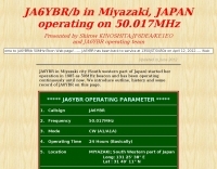 JA6YBR/b in Miyazaki, JAPAN operating on 50.017MHz
 -
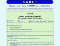
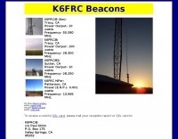 50Mhz 28Mhz 13.5Mhz amateur radio propagation beacons by K6FRC
 -
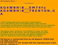
 Beacon website of WE4S, Grady Donaldson, located in McDonough, GA. EM73TM.
 -
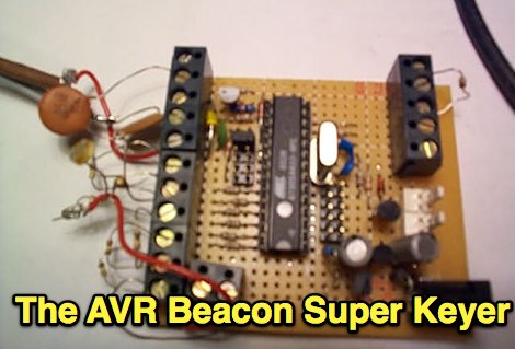
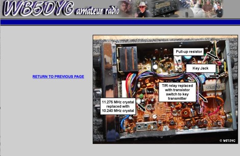
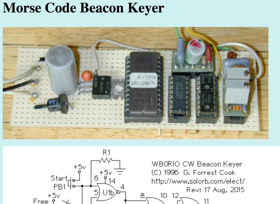 This circuit stores a morse code message as bits in an EPROM chip, the message controls a relay that keys a CW morse code transmitter. An Arduino processor can also be used in place of this circuit, that eliminates the need to build the circuit and program an EPROM.
 -
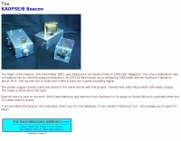
 The next generation beacon platform for the OZ7IGY beacons should encompass both the analog and digital mode, i.e. FSK and MGM in a mixed mode configuration
 -
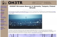 OH3TR operates the OH3SHF microwave beacons on 2.3, 3.4, 5.7, 10 and 24 GHz
 -
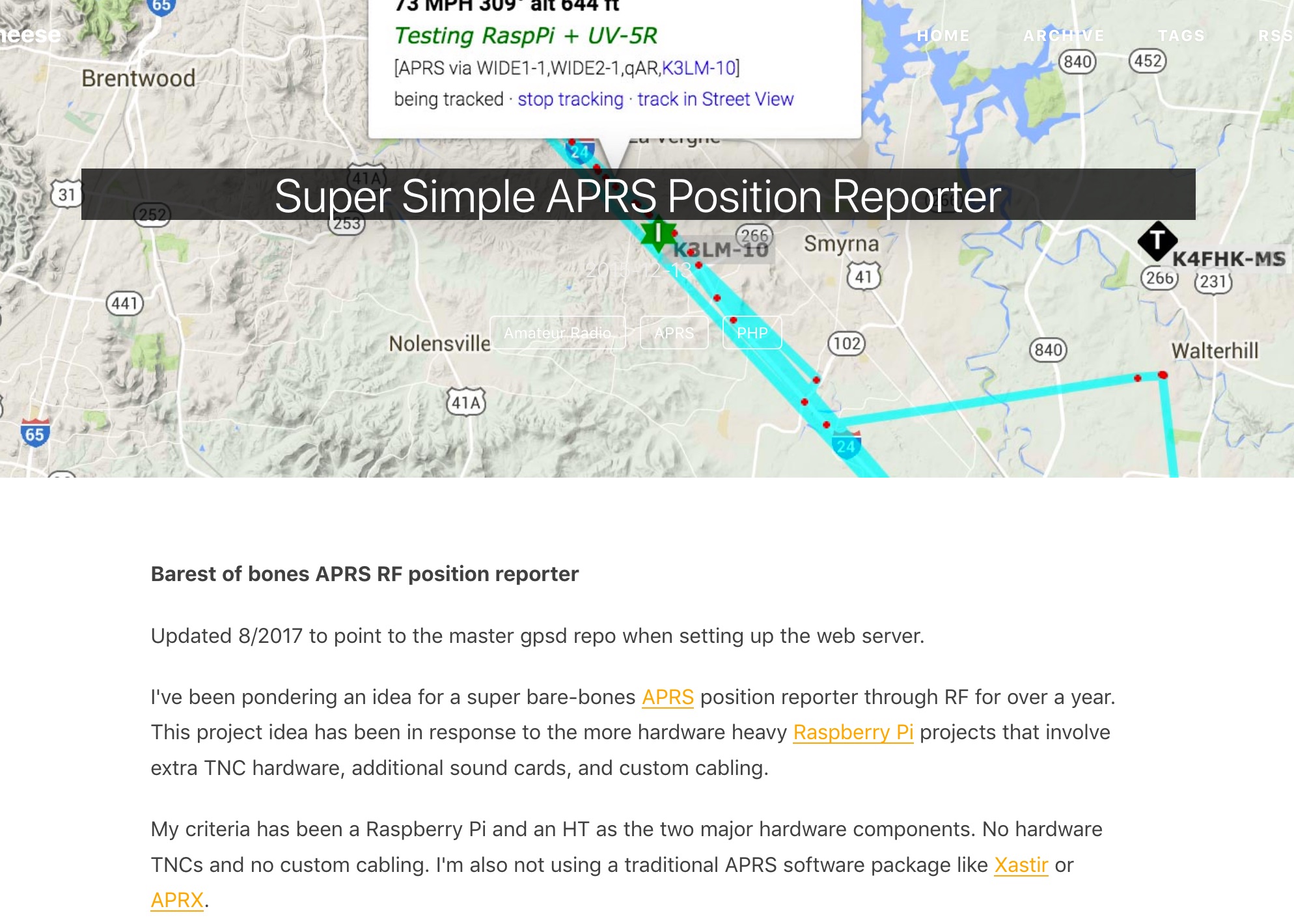 Barest of bones APRS RF position reporter using a Raspberry Pi B+, USB GPS receiver, Baofeng UV-5R, and a mono 3.5mm audio cable between the Pi and the radio
 -
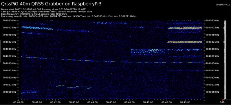 Monitoring extremely weak signals in the QRSS (Very Slow Morse) mode requires specialized receiving and processing capabilities to extract information below the typical noise floor. This project provides a software solution, _QrssPiG_, designed to run on a Raspberry Pi, enabling it to function as a dedicated QRSS grabber. It interfaces with various Software Defined Radio (SDR) devices, including the popular _rtl-sdr_ dongles and _HackRF_ units, to acquire raw I/Q data streams. The software then performs the necessary signal processing to visualize and decode these faint, long-duration CW transmissions, often operating with milliwatts of power. The system leverages the computational power of the Raspberry Pi for real-time signal analysis, allowing hams to participate in QRSS experiments and monitor distant beacons. It supports different SDR hardware, offering flexibility in setup and deployment for home stations or remote monitoring sites. The project includes detailed instructions for installation and configuration, making it accessible for those familiar with Linux environments. This grabber is particularly useful for tracking propagation on the LF and HF bands where QRSS activity is common, providing a visual representation of signal presence over extended periods.
 -
 G6LVB beginners guide to receiving the AO-40 beacon
 -
-
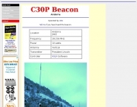 Amateur radio station c31lj andorra 28.256 MHz
 -
 The RBN S-Meter visualizes real-time HF propagation data from the Reverse Beacon Network (RBN). It processes thousands of automated spots per hour, providing a real-time picture of active RF paths on HF bands. Users can set their vantage point using _Region Mode_ or _Grid Square Mode_. Region Mode allows selection from broad geographic areas like E. North America or Europe, while Grid Square Mode uses a Maidenhead grid square and radius for more precise data. The app displays eight region panels, each with horizontal bars for bands 160m through 6m, indicating signal strength with a color ramp from green to red. A dimmer trail shows peak hold values, and an S-unit readout provides additional detail. The app is a free web application accessible on any device, offering a practical tool for ham radio operators interested in CW, RTTY, and FT8 signals. It features a Progressive Web App installation option for enhanced usability on mobile and desktop platforms. Users can install it on Android, iOS, and Windows devices, providing a native app-like experience. The app replaces the previous Windows standalone executable, incorporating user feedback to improve features like grid square mode and automatic location detection.
 -
-
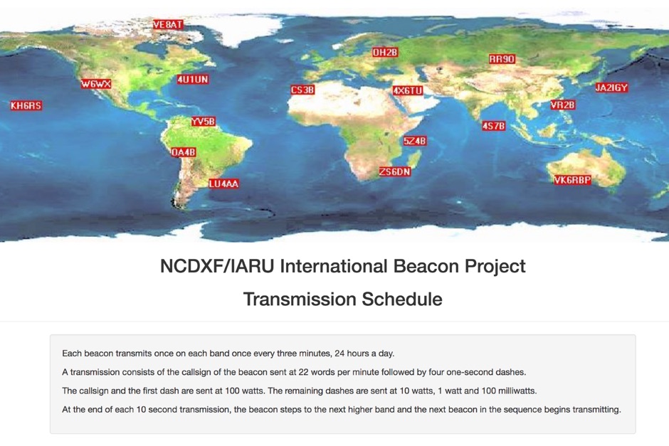 Whatch at beacons transmitting in real time. This page contains a self refreshing table that displays every 10 seconds the current transmission schedule of the international beacon project. Tune your radio and check the beacon you are hearing.
 -
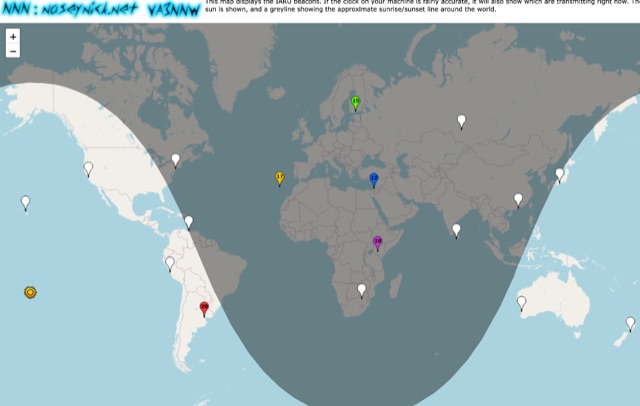 This online map shows the IARU beacons. If the clock on your PC is accurate enough, it will also show which ones are broadcasting at the moment and on which band.
 -

-
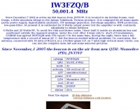
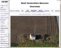 The world's oldest beacon OZ7IGY in JO55WM 28 MHz to 24 GHz.
 -
-
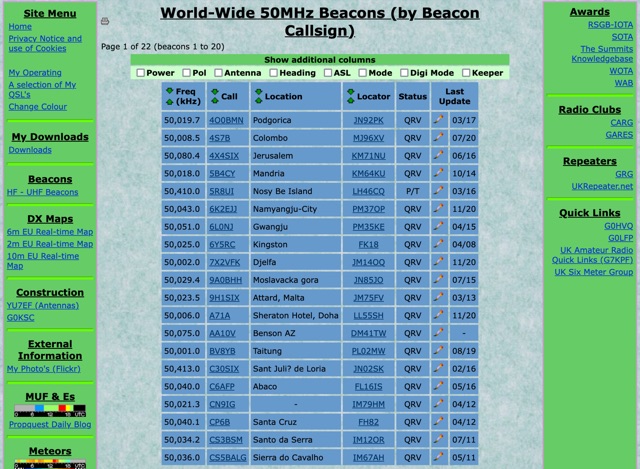 World-Wide 50MHz Beacons database maintanied by G0LGS provide a fully sortable table available also in a google map format
 -
-
 The ZS1J/B beacon operates on 28.2025 MHz with 5 Watts output to a half-wave, end-fed vertical antenna, initially installed in 1977 as ZS5VHF near Durban. The 10-meter transmitter is a modified 23-channel CB radio, and the identification keyer uses a diode matrix unit with TTL ICs from the same era. After relocation to Plettenberg Bay in 1993, the beacon has been in continuous service, with additional QRP transmitters later installed for other bands. In 1994, a single-transistor, 80-meter, 0.5-watt QRP transmitter with a half-wave dipole was added on 3586 kHz, followed by a 160-meter, 0.5-watt unit on 1817 kHz. A 30-meter, 0.5-watt transmitter was installed in 1996, operating on 10.124 MHz. In 2002, a 40-meter QRRP beacon on 7029 kHz, with an output of 100 microwatts, achieved DX reports up to 1100 km from ZS6UT in Pretoria. Best DX reports for the 80m and 160m beacons came from 9J2BO.
 -

-
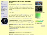 Beacon Reception at JN1SDD by SoftRock and Octave
 -
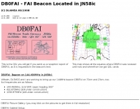
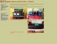
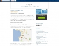
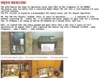
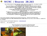
 On 28.219 Mhz it puts out a whopping 3.85 watts into an inverted V dipole at about 30 ft.
 -
-
-
-
 Description of an HF beacon keyer with telemetry. What makes the keyer rather different is its versatility - it is a multi-mode unit, with ASK and FSK modulation, sending Feld-Hell and Morse on command
 -
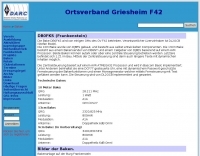
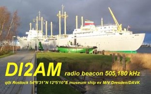 The radio beacon DI2AM on museum-ship in Rostock Schmarl
 -
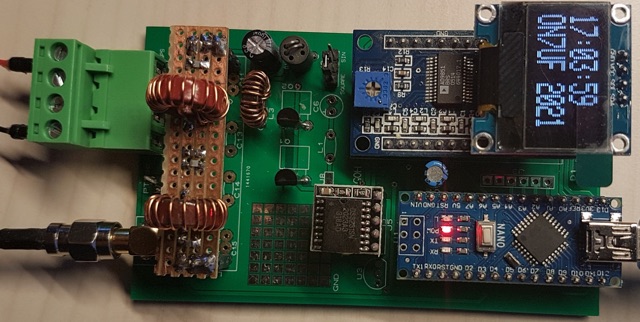 A WSPR beacon project based on Arduino nano (atmega328P) based microcontroller
 -
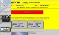 Two beacons in 3 and 1.2 cm band, 10368.755 MHz and 24048.870 MHz
 -
-
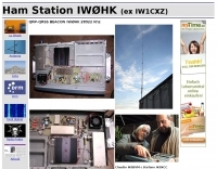
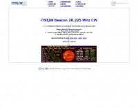
 28,227.5 MHz, from JN55VF first "IW" prefix beacon "ON THE AIR" activated from Italy
 -
-
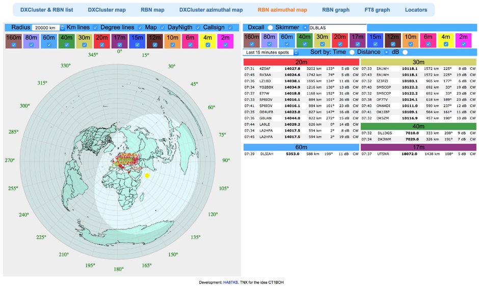 Reverse Beacon Network (RBN) remdered in a Real-Time Azimuthmal Map centered on a custom call sign
 -
-
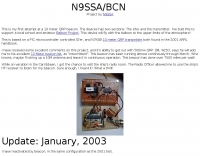
 28.222mhz transmitting with 2 watts of power
 -
 DF0WD/DL4YHF's Longwave Overview details amateur radio operations on the 135.7 to 137.8 kHz segment in Germany. The author outlines the "inofficial" European band plan, specifying segments for QRSS, TX tests, beacons, conventional CW, and data modes. Early LF activities at DF0WD began with a 20-watt CW transmitter, later upgraded to a homemade linear transverter capable of 100 watts, driven by an Icom IC706 on 10.137 MHz. The station's antenna system includes a 200-meter wire, approximately 10 meters above ground, supported by football field light-masts. Despite its length, the antenna's efficiency is noted as very low due to the immense wavelength of about 2.2 km. The author's experience highlights the significant challenge of achieving effective radiated power (EIRP) on LF, estimating DF0WD's EIRP at around 80 milliwatts based on field strength measurements from PA0SE. DF0WD/DL4YHF has successfully worked numerous countries on 136 kHz CW, including DL, F, G, GI, GM, GU, GW, HB9, HB0, LX, OE, OH, OK, OM, ON, OZ, PA, and SM. The author also mentions ongoing efforts to log contacts with CT, EI, LA/LG, and to complete a two-way QSO with Italy, demonstrating persistent activity on this challenging band.
 -
-
 AC7GZ/B is a converted Sharp CB-2460 Citizens Band transceiver operatin on 28.2118 MHz.
 -
-
-
-
-
-
 N4PAL 10 Meter, 28.214MHz Radio Beacon Site Information and Siginal Report Logging