Search results
Query: 20 meter
Links: 529 | Categories: 6
-
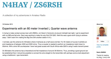 Experiments with an 80 meter Inverted L Quarter wave antenna
 -
 The Yaesu VX-5R, manufactured between 199x and 200x, offers a transmit frequency range covering 50-52 MHz, 144-146 MHz, and 430-440 MHz for European models, with US versions extending to 50-54 MHz, 144-148 MHz, and 430-450 MHz. Its receiver boasts an impressive wideband capability from 0.5 MHz to 999 MHz, with cellular frequencies blocked in some regions. The unit provides up to 5 watts RF output on 6 meters and 2 meters, and 4.5 watts on 70 centimeters, with selectable lower power settings down to 300 mW. This handheld transceiver utilizes a double conversion superheterodyne receiver system, featuring a 47.25 MHz first IF for FM and 45.8 MHz for WFM. Key specifications include a frequency stability of ±5 ppm across a wide temperature range and a current drain of 25-150 mA on receive. The VX-5R supports 220 regular memory channels with alpha tags, 3 home channels, and 10 NOAA weather channels, all stored in non-volatile EEPROM. Additional features include CTCSS/PL and DCS with tone search, ARS, ARTS, an internal voltmeter, and a Spectra-Scope. The device operates on a 7.2 VDC battery pack or 10-16 VDC external power, weighing 255 grams with dimensions of 58x88x27 mm. The VX-5R was also available as the metallic silver VX-5RS.
 -
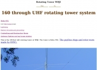 This is the 195-foot tall rotating Rohn 55G tower at W8JI with yagis for 40 20 15 and 6 meter bands.
 -
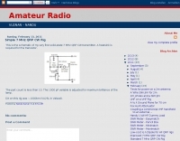 This is the schematic of asolid-state 7 MHz QRP CW transmitter by VU2NAN
 -
-
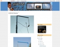
 This antenna is intended for the 20-meter Band. There are two Voltage Fed Helical Dipoles, made with 2 slinky that fed with phase shift in 90 degree
 -
 An home made magnetic loop antenna project using a military surplus 150pf capacitor by KF5CZO
 -
 An homebrew project for a 3 element coil-loaded Yagi beam antenna for 40 Meter band
 -
 Demonstrates the adaptation and construction of a 7-element DK7ZB Yagi antenna for the 4-meter band (70 MHz), utilizing components from a defunct 2-meter CUE DEE Yagi. The resource details the modifications made to the original DK7ZB design to fit the shorter CUE DEE boom length, specifically adjusting element lengths for 6mm rod elements while reusing existing mounting holes for the reflector and last director. It provides precise element lengths for the reflector, dipole (12mm aluminum tube), and five directors, along with a note on cutting elements for transport. The article includes a 4NEC2 simulation file for performance analysis and an SWR plot, confirming the antenna's electrical characteristics. It also specifies the calculation for the quarter-wavelength matching cable using SAT752F coaxial cable, resulting in a 909mm length. Practical application is shown with the finished antenna in operation at JO20XC, listing several activated Maidenhead squares such as JO56PA and JP40KS, validating its effectiveness for portable 70 MHz operations.
 -
 This PDF document details the construction of a **70 MHz** Big Wheel antenna, a horizontally polarized omnidirectional array. The design utilizes three full-wave loops, each approximately **2160 mm** in diameter, arranged in a triangular configuration. The resource provides mechanical dimensions for the antenna elements and a comprehensive bill of materials, specifying component quantities and types, such as M8 stainless steel bolts, 15x15x1.5 mm square aluminum tubing for spacers, and 8 mm aluminum rod for the arcs. The central hub is constructed from two 160x160x8 mm aluminum plates, with four 40 mm long polyamide insulators supporting the radiating elements. The feed system incorporates a 50 mm diameter aluminum pipe for mounting and a matching stub constructed from a 120x20x2 mm aluminum sheet, connected via M8x10 mm bolts. The resource includes a diagram illustrating the mechanical dimensions and assembly points, including the N-connector fixing point and the center conductor attachment. The project was published on May 25, 2011, by Peter OE5MPL and Rudi OE5VRL. DXZone Focus: PDF | 70 MHz Big Wheel | Mechanical Dimensions | **2160 mm** loop diameter
 -
 A simple low-power broadcast-type circuit, using a crystal oscillator integrated circuit and an a collector modulated AM oscillator
 -
 Homemade Loaded Coil Dipole ( w8010 diamond ) for 10, 15, 20, 40 and 80 meter
 -
 Homebrewed transceiver for 20 meter originally born for 17 meters band
 -
 K0GKJ project of a copper tube slim jim antenna for two meter band
 -
 Article describing how to homebrew a yagi antenna for 50 MHz, includes plans for a four and five elements yagi beam and details how how match impedence with a gamma match
 -
 Cannot record CW message, AFSK not working, tracking not working, meter peak hold, on Yaesu FT-920.
 -
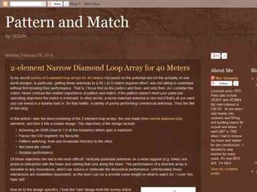
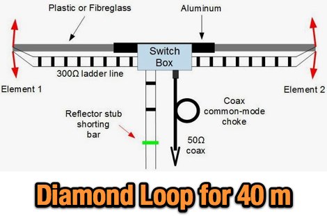 A 2 element Narrow Diamond Loop Array for 40 Meters by VE3VN
 -
 A three band short Vee antenna is feasible with two legs per side on a dipole. 10-15-20 meters by W8HDU
 -
 Phased wire vertical antennas for 40 meters band
 -
 A Co-ax Trap Dipole For 40, 30 and 20 Meters or at last that was the intention
 -
 The X80 multi-band HF vertical antenna, a commercial iteration of the Rybakov design, exhibits a physical length of 5.5 meters, or approximately 18 feet, and is constructed from aluminum tubing. It operates as a non-resonant vertical, requiring an external antenna tuner for impedance matching across its intended operating frequencies. The antenna's design incorporates a 1:4 UNUN at its base, facilitating a nominal 50-ohm feed point impedance for the coaxial cable. Performance observations indicate effective operation on 40 meters, 20 meters, 15 meters, and 10 meters, with reduced efficiency on 80 meters and 160 meters due to its relatively short electrical length for these lower bands. Comparative analysis with a G5RV dipole and a half-wave end-fed antenna reveals the X80 offers a lower take-off angle, beneficial for DX contacts, particularly on the higher HF bands. Field tests conducted with an Icom IC-706MKIIG transceiver and an LDG AT-100ProII autotuner demonstrate the X80's ability to achieve acceptable SWR across 80m through 10m. The antenna's compact footprint and ease of deployment make it suitable for restricted spaces or portable operations, though its performance on 80 meters is noted as a compromise compared to full-size resonant antennas.
 -
 The ZS6BKW multi-band antenna, an optimized variant of the classic G5RV, is presented with detailed construction and tuning instructions. This resource outlines the antenna's design principles, which were developed by _Brian Austin (G0GSF)_ using computer programs and Smith charts to achieve optimal dimensions. It provides specific guidance on calculating and adjusting the lengths of the radiators (L1) and the matching ladder line (L2), emphasizing the critical role of velocity factor (VF) in achieving resonance. The article includes a step-by-step procedure for empirically determining the VF of ladder line using an antenna analyzer, ensuring accurate physical lengths for the matching section. It details the tuning process for the radiators, offering practical tips for incremental adjustments to achieve the best SWR curve. The resource presents SWR measurement results obtained with an _AIM-4170C_ analyzer across multiple bands, alongside predicted SWR graphs from an AutoEZ model. It confirms successful contacts on 80, 40, 20, and 17 meters, including a **17-meter DX contact** to Italy. EZNEC and AutoEZ models for the ZS6BKW antenna, covering 80 through 6 meters, are provided for download, allowing further analysis and customization. The document specifies component details, such as the use of Wireman 554 ladder line and #14 AWG THHN copper wire, and discusses the antenna's performance characteristics, noting high SWR on 15 and 30 meters but successful tuning on 6 and 80 meters with an external tuner.
 -
 The resource details the construction of a homebrew 50-watt FET amplifier, based on Don W6JL's _QST Homebrew contest_-winning design from 2009. It functions as an afterburner for QRP transceivers, providing a **12dB** power lift. The amplifier utilizes IRFZ24N FETs and covers the 80, 40, 30, and 20-meter bands, with the 20m LPF extending to 17m. Key technical aspects include an FT37-43 transformer for the input network, a relay-switched 3dB pad for lower bands controlled by an _Arduino Nano_, and an RF-actuated T/R switch. The LPF board integrates four relay-switched filters rated for 50 watts, using capacitors with a minimum 250VDC rating. Performance measurements indicate a power gain ranging from **4.4dB** on 20m to 8.1dB on 80m, with a required drive power of approximately 5 watts. The article also discusses thermal management, current limiting considerations, and component sourcing.
 -
 Repairt a Heathkit SB-220 Linear Amplifier with a bad Plate Voltage meter
 -
 A hombrew QRP transceiver for 40 meter band with many pictures, circuit and sound recording of some QSOs made with this Rig consisting of 5 transistor and one chip.
 -
 Demonstrates various practical amateur radio projects and technical discussions through video episodes. One episode details cutting and retuning a _1/4 wave shorted stub_ from 101.7 MHz to 107.5 MHz to safeguard a transmitter's driver stage, alongside insights into advanced _160-meter antenna systems_ like eight-circle arrays and beverage antennas. Another segment covers upgrading firmware on an _ATS-20+_ receiver using AverDudes for improved display and functionality, and a detailed guide on using D-Star DR mode on an _ICOM ID-52A_ for international repeater programming. Additional content includes a deep dive into _OpenHamClock_ as a potential replacement for the HamClock project, updates on _Raspberry Pi 5_ running Trixie OS, and a review of the Choyong LC90 Internet radio with AI integration. The series also features "Ham College" episodes, which meticulously prepare viewers for the Technician Exam by covering topics such as antenna and transmission line measurements, SWR interpretation, and the functions of basic electronic components like rectifiers, relays, and transistors. Practical advice on coaxial cable characteristics, dummy loads, and proper soldering techniques is also provided.
 -
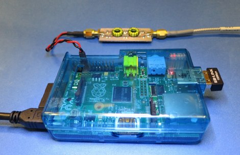 Settng up a 40 meter WSPR beacon based on Raspberry Pi by VA3PAW
 -
 A project that describes a build a multiband wire beam antenna. A 3 band single feed moxon antenna for 20,15,10 meters.
 -
 Antenna model for a diamond loop wire antenna for the 40 meter band
 -
 Demonstrates the operational status and reception reports for the SK6RUD/SA6RR QRPP beacons, which transmit on 478.9 kHz, 1995 kHz, 10.131 MHz, and 40.673 MHz. These beacons utilize extremely low power, with the 630-meter beacon operating at approximately 0.1 watt ERP into an L-antenna, showcasing the potential for long-distance contacts under favorable propagation conditions. The site details the specific frequencies and antenna types employed, such as a vertical at 500 kHz and a 1/4 vertical for higher bands. The resource compiles over 10,530 reception reports from amateur radio operators worldwide, logging details such as date, time, band, RST signal report, locator, distance, and receiver setup. Notable long-distance reports include a 500 kHz reception by AA1A-Dave from 5832 km in 2008 and a 10.133 MHz reception by ZL2FT-Jason from 17680 km in 2010, illustrating the global reach of these low-power transmissions. Each log entry provides specific equipment used by the reporting station, including transceivers like the Yaesu FT817, ICOM IC-7300, and various antenna configurations such as coaxial mag loops, inverted Ls, and end-fed wires. The primary objective of the SK6RUD beacons is to challenge conventional notions of power requirements for effective two-way communication, proving that contacts over significant distances are achievable with minimal output. The site also includes a submission form for new reception reports, fostering community engagement and continuous data collection on propagation phenomena across different bands. The detailed logs offer practical insights into real-world propagation characteristics and the efficacy of QRPP operations.
 -
 This page presents a curated list of individuals who have made significant contributions across various fields while also being active amateur radio operators. For instance, Dr. Joseph H. Taylor, co-winner of the 1993 Nobel Prize in Physics for the discovery of binary pulsars, is recognized for developing the _WSPR_ and _WSJT_ weak signal mode software. Similarly, Wilson Greatbatch, inventor of the cardiac pacemaker with over **150 patents**, is featured. The resource details the diverse backgrounds of these hams, from Professor Donald H. Menzel, an astrophysicist at Harvard, to Hiram Percy Maxim, often called "The Father of Amateur Radio," who also pioneered in the automobile and aviation industries. King Hussein of Jordan, JY1, is noted for his active participation on 20 meters, engaging with fellow amateurs like Pat Kilroy, WD8LAQ. Other entries include Arthur M. Young, designer of Bell Helicopter's first model, and Marlon Brando, KE6PZH/FO5GJ, known for operating from his private island in French Polynesia. Peggy Sue Gerron-Rackham, K5PSG, gained her license after a special event station, demonstrating the hobby's broad appeal.
 -
 Delta loop antennas for 40 meters plans and comparison of some models
 -
 In this experiment the autor is going to explore the use of a 1:64 matching network on the End Fed Long Wire Antenna. Experiment will consist in build a 80-40-20-15-10 meter End Fed Long Wire Antenna with a 1:64 matching network from the documentation available on the internet
 -
 Designing and constructing portable wire antennas for HF operations, this resource explores several configurations including the _foldback dipole_ for space-constrained setups and an inductively shortened dual-band dipole for 20m and 40m. It details the calculation of inductance for shortened elements, providing a Visual Basic 6.0 program screenshot that illustrates determining coil parameters like turns and length for a **25.5 uH** inductor. The document emphasizes practical considerations such as adjusting wire lengths for optimal SWR, noting that a dual-band dipole achieved SWR below 2:1 on both 20m and 40m, with careful adjustment bringing it under 1.5:1. Further, the resource describes a half-wave antenna matched with a coaxial stub, a method often referred to as the _Fuchskreis_ in German amateur radio circles, to transform the high feedpoint impedance to 50 Ohms. This monoband solution, for a 20m application, uses a stub length of **2.98m** (0.216 lambda multiplied by coax velocity factor) and a shorted stub of approximately 48cm. The coaxial stub design is highlighted for its resilience to ground proximity, allowing it to be rolled up or laid on the ground with minimal SWR impact, making it highly suitable for portable QRP operations.
 -
 The page discusses the concept of a 2-element Parasitic Ground Plane antenna for the 40-meter band. It includes a conversation between amateur radio operators discussing modeling results and design considerations for the antenna. The author shares insights on radial configurations and the impact on antenna efficiency and pattern.
 -
 Schematic diagram and description of a magnetic loop antenna that works from 10 to 20 meters band, made from junk
 -
 A multi band portable link dipole antenna for 20 30 and 40 meters band
 -
 Testing performances of indoor antenna. A comparison of a magnetic loop antenna vs a classic wire dipole done using wsprlite on 30 meters band.
 -
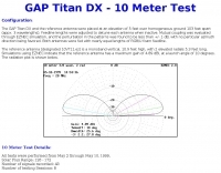 GAP Titan DX 10 15 20 40 meter performance tests by AA3RL
 -
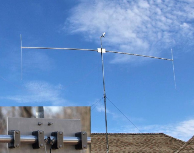 Construct a compact, 20 meter rotatable dipole antenna of durable weather worthy components supported at a single point obviating the need for multiple supports and multiple support ropes crossing the yard.
 -
 An home made HF mobile multiband antenna inspired by the KM4IE HF 20 dollars antenna or the Texas Bugcatcher can work 75 to 15 meters band with an acceptable SWR.
 -
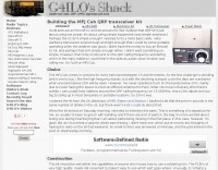 Building the MFJ Cub QRP transceiver kit for 20 meters band by G4ILO
 -
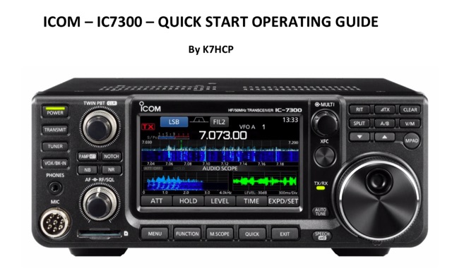 PDF document for IC-7300 beginners. The ICOM IC-7300 is an HF + 6 meter, multi-mode, self-contained Software Defined Radio (SDR) transceiver with knobs, buttons and a touch screen. It also has a real-time spectrum display with pan adapter and water fall displays.
 -
 The **KC0KJF** personal amateur radio page provides a collection of resources for fellow hams, particularly those interested in operations within southwest Missouri. It offers detailed listings for **Missouri repeaters** on both 2 meters and 70 centimeters, serving as a practical reference for local VHF/UHF communication. The site also includes information about the operator's station setup and antenna projects, such as a dipole and a bazooka antenna, which can offer insights into basic antenna construction and deployment. Beyond local repeater data, the page features links to the FCC Part 97 rules, essential for understanding amateur radio regulations. The operator, licensed as a Technician Class since April 16, 2001, shares his journey from Citizen's Band Radio to amateur radio, driven by a lifelong fascination with shortwave listening. This narrative provides context for the resource's focus on practical operating information and foundational regulatory knowledge. Additional content covers specific equipment like the 2-meter/70-centimeter Arrow Antenna, useful for hams considering portable or fixed station VHF/UHF setups.
 -
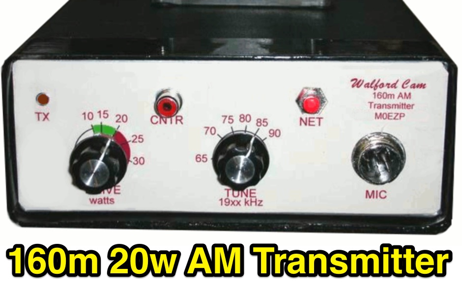 Born as a companion transmitter for the Yaesu FRG-7 receiver has become a stand alone tramsmitter for 160 meters band
 -
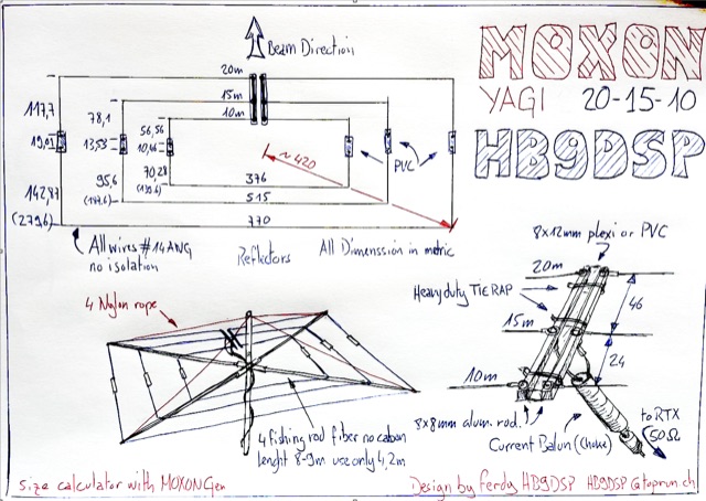 Multi band Moxon Yagi Antenna for 10,15,20 meters band with just one feed line. Drawing and project with dimensions
 -
 An homebrew project of a full wave delta loop antenna for the 40 meters band with dimensione, picture and assembling instructions in Indonesian
 -
 A wire antenna feeded with an unsymmetrical feed and a 1:4 balun can be tuned from 6 to 80 meters band but can be noisier than a dipole and cause RF in the shack
 -
 Slot cubes are folded skeleton slot antennas with widened, folded dipoles bent into a cube to reduce size. QST Article 12 2019
 -
 An comprehensive article on 40 meters antenna comparing vertical height to the resulting gain