Search results
Query: 6m
Links: 357 | Categories: 2
-
 Simple QRP projects, 10m, 6m, WSPR beaconing, sub-9kHz and other random stuff
 -
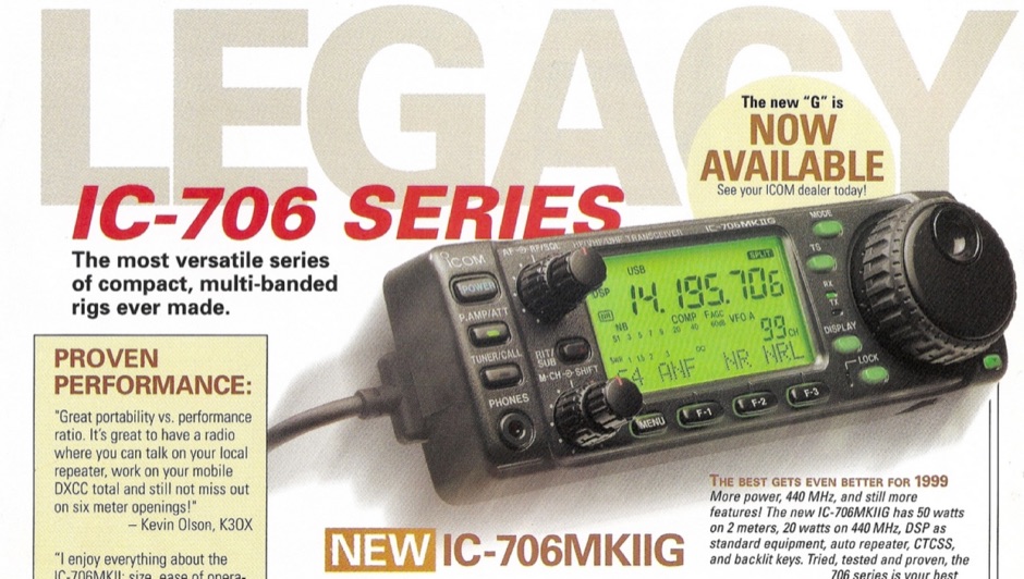 Review of the Icom IC-706 series, include a short demo video and a short menu table available for download
 -
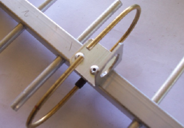 23cm 1296 MHz Field Day Yagi Construction, a 26 element conventional-style design. Article with several pictures and detailed homebrewing instructions
 -
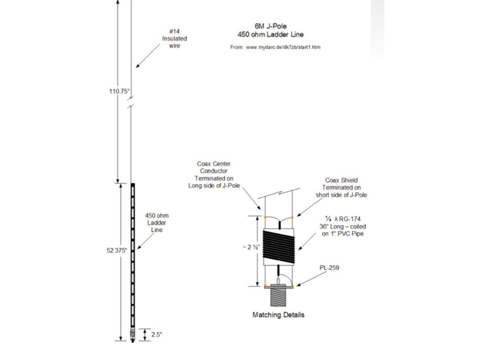 A J-pole antenna plan for 50 MHz based on the DK7ZB design
 -
-
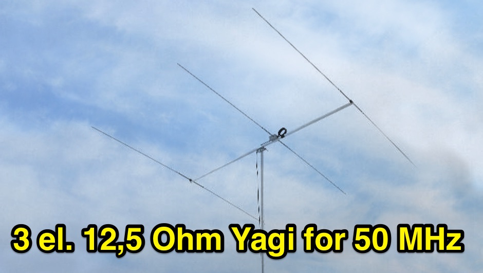 Article about a high-gain, narrow-band version feature 7.15 dBd and a F/B 13dB with details on how to setup in array mode
 -
 An homemade HF, 6m, 2m SSB CW transceiver project by m0dgq
 -
-
 Documents the OC1I and OC6I IOTA DXpeditions to Peru, specifically highlighting operations from SA-098 (Isla La Leona) and SA-076 (Isla Lobos de Afuera). The OC1I team logged over **8000 QSOs** from SA-076, while OC6I made 1400 QSOs from SA-098, despite challenging propagation conditions. The resource details the equipment used, including an _IC-7000_, an IC-706mkIIG, and a TS-440SAT, along with various antennas such as a 160m dipole, FD4, G5RV, and a multi-band vertical for 17m, 20m, 30m, and 40m. The DXpedition dates are specified: OC6I operated from SA-098 between December 28 and December 30, while OC1I was active from SA-076 from January 2 to January 7. Both operations are confirmed as valid for IOTA credit. The page also includes a video link for the OC6I operation and a photo gallery from the DXpedition. Feedback is welcomed, and the webmaster is identified as Bodo Fritsche, DL3OCH.
 -
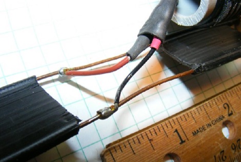 6 Meter J-Pole from 450 Ohm Ladder Line a quickie project
 -

-
 9M6MU Alfons details his family's efforts to establish an independent, self-sufficient home at Eagle Plateau in Borneo, a 50-acre highland property. The resource highlights their integration of **solar photovoltaic panels** for power generation, alongside managing water supplies, organic gardens, and fruit trees. It covers the practical challenges and rewards of living off-grid, including maintaining power generators and addressing infrastructure needs, all while pursuing the hobby of amateur radio. The narrative emphasizes a holistic approach to healthy living and nature conservation, reflecting the family's aspirations for an ideal ham world. Alfons and his XYL Doris share their experiences in building shelter and antenna farms, showcasing their dedication to independence and sustainable practices away from the conventional grid. The site also references the Hillview Gardens Amateur Radio Club, suggesting community involvement.
 -
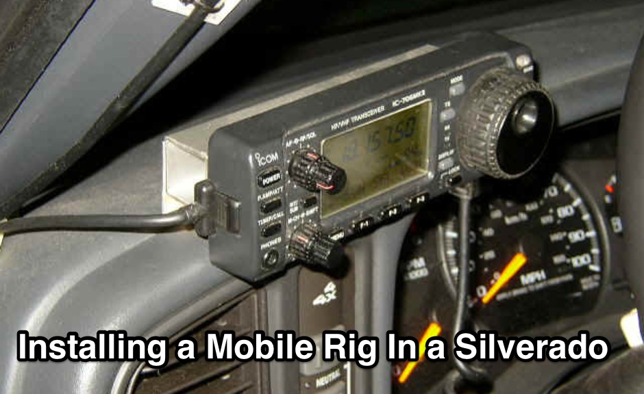 Installing a mobile rig in a vehicle requires careful planning and execution to ensure optimal performance and safety. The process begins with selecting the right equipment, such as the ICOM IC706MKII for low bands and the ALINCO DR-610 for VHF/UHF operations. Proper mounting is crucial; both radios are strategically placed under the back seat of the Silverado, allowing for a clean installation while maintaining passenger comfort. The Hustler antenna, equipped with various resonators, ensures coverage across multiple bands, while the LDG automatic antenna tuner fine-tunes the match for efficient operation. A remote head for the tuner enhances accessibility, making adjustments easier while driving. Each step of the installation is documented to provide insights and tips for fellow operators looking to enhance their mobile setup. The experience shared here reflects practical knowledge gained through hands-on work, aiming to inspire others in the ham community to undertake similar projects.
 -

-
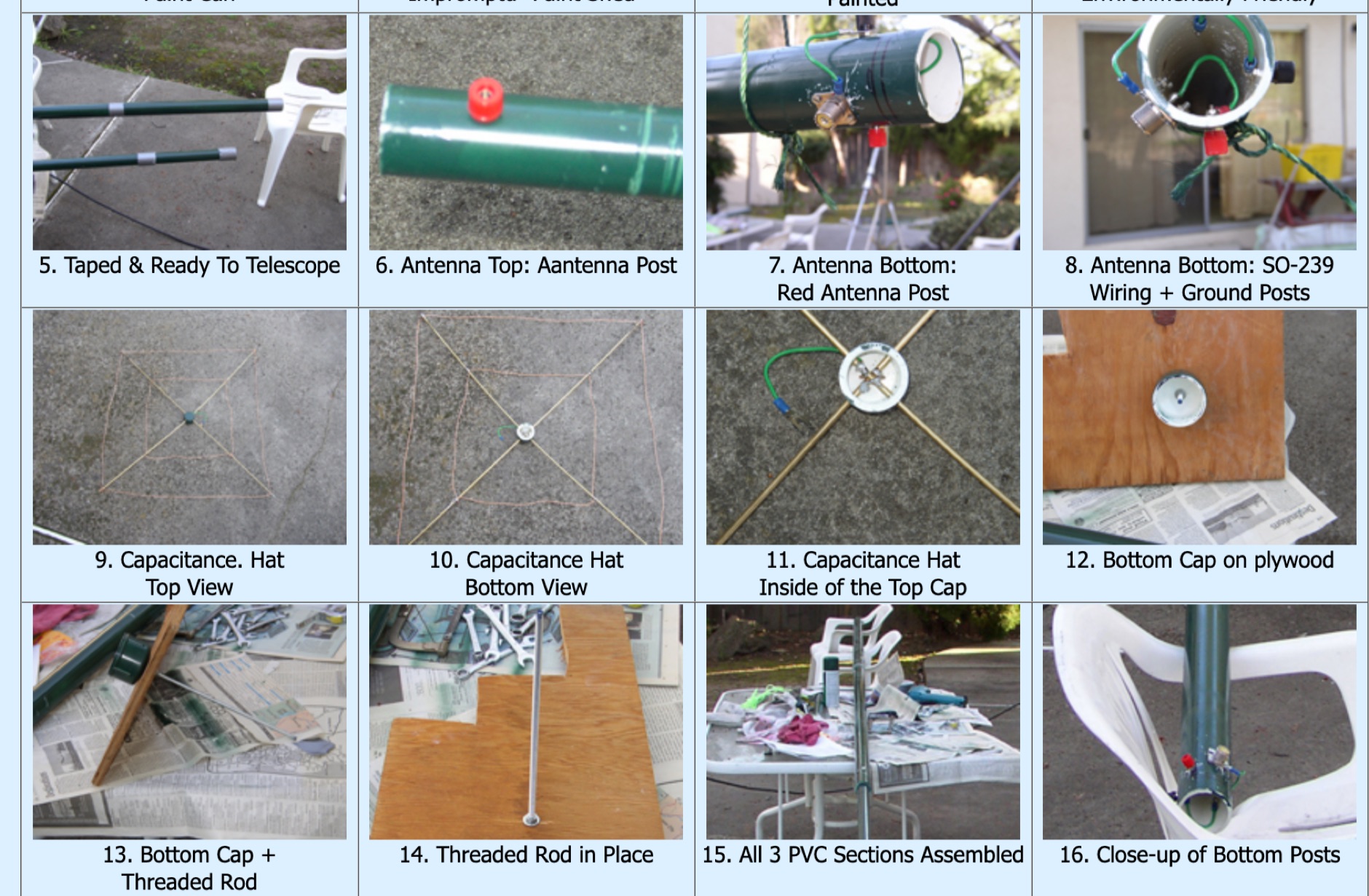 This antenna is designed for stations having a difficult time putting a decent signal on 160M from small or CC&R d lots. It is a 24.5 ft. vertical antenna, made from three 10 ft. PVC sections bolted together, and half wavelength of antenna wire helically wound around the PVC sections.
 -
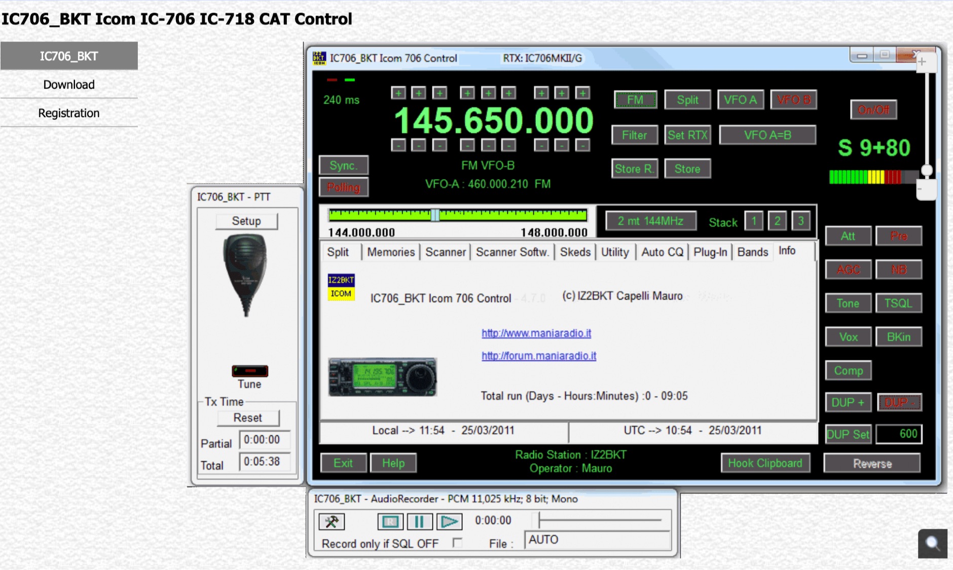 IC706_BKT CAT is used to control the transceiver Icom IC-706, IC-706MKII IC-706MKII/G and IC-718 from the personal computer. Works on Windows and is available in free and free donation version
 -
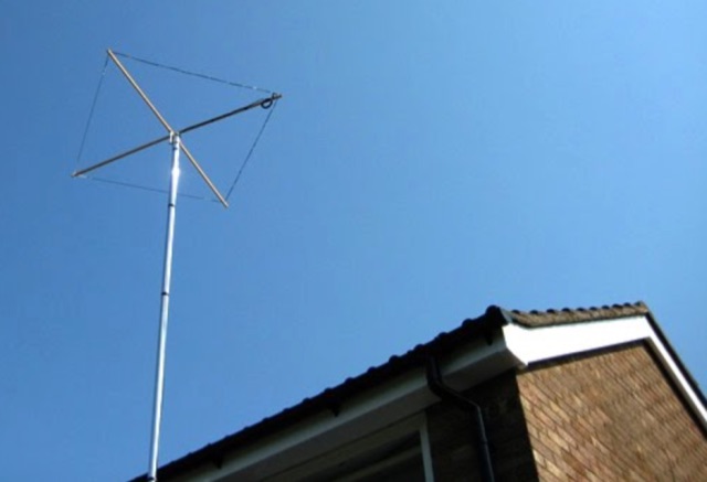 The Homebase-10 is a wire halo antenna for 10m built with DIY store parts, effective despite its small size. Includes a dual-band version for 10m and 6m with gain around 0 to -2dBd, near omnidirectional pattern, and horizontal polarization. Overview based on a 2008 Practical Wireless article.
 -
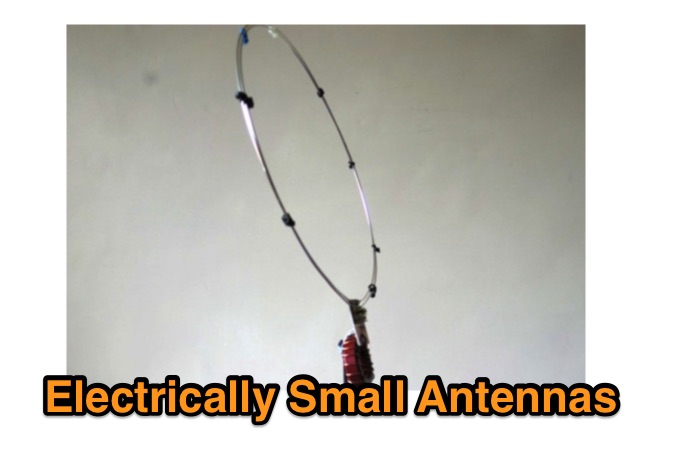 An antenna system is electrically small if it's enclosing sphere is <λ/2π. So a 10m band antenna of under 1.6m long qualifies.
 -
 Making EME contacts on six meter band. An US Experience using a pair of 8 yagi arrays for the 50 Mhz.
 -
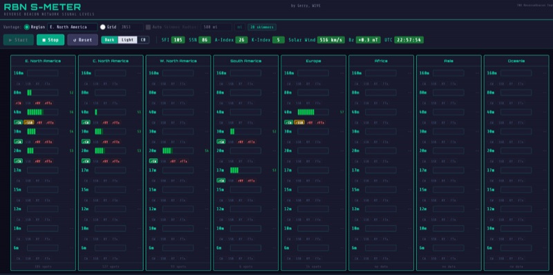 The RBN S-Meter visualizes real-time HF propagation data from the Reverse Beacon Network (RBN). It processes thousands of automated spots per hour, providing a real-time picture of active RF paths on HF bands. Users can set their vantage point using _Region Mode_ or _Grid Square Mode_. Region Mode allows selection from broad geographic areas like E. North America or Europe, while Grid Square Mode uses a Maidenhead grid square and radius for more precise data. The app displays eight region panels, each with horizontal bars for bands 160m through 6m, indicating signal strength with a color ramp from green to red. A dimmer trail shows peak hold values, and an S-unit readout provides additional detail. The app is a free web application accessible on any device, offering a practical tool for ham radio operators interested in CW, RTTY, and FT8 signals. It features a Progressive Web App installation option for enhanced usability on mobile and desktop platforms. Users can install it on Android, iOS, and Windows devices, providing a native app-like experience. The app replaces the previous Windows standalone executable, incorporating user feedback to improve features like grid square mode and automatic location detection.
 -
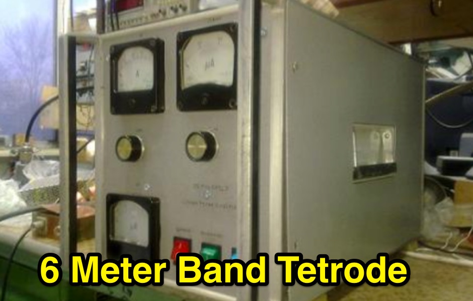 Demonstrates the construction of a high-power 6-meter (50 MHz) amplifier, specifically designed for demanding modes like EME, TEP, and multiskip Es. It details the use of a _GU-43B_ tetrode in a grounded-cathode configuration, emphasizing the need for stabilized grid voltage and input capacitance compensation. The resource provides a comprehensive schematic, power supply design, and practical considerations for component sourcing, particularly for high-voltage and high-current sections. The builder achieved an output power of **1250 watts** with an anode current of 0.65 amperes and 3200 volts anode voltage. The article also covers the physical construction within a modified P6-31 enclosure, outlining the internal layout for RF and power supply sections, and includes photos of the completed unit. It highlights critical safety precautions for working with high voltages and reactive currents up to **20 Amperes** in the P-network.
 -
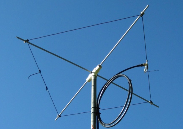 The antenna described in this article is for 50 MHz, but the design can be scaled for any band, including VHF, UHF, or even the higher HF bands. The antenna is nothing more than a square loop of wire, approximately 30" (or ~76cm) per side. The loop is fed in the middle of one side, and the opposite side to the feed point has a gap in it.
 -
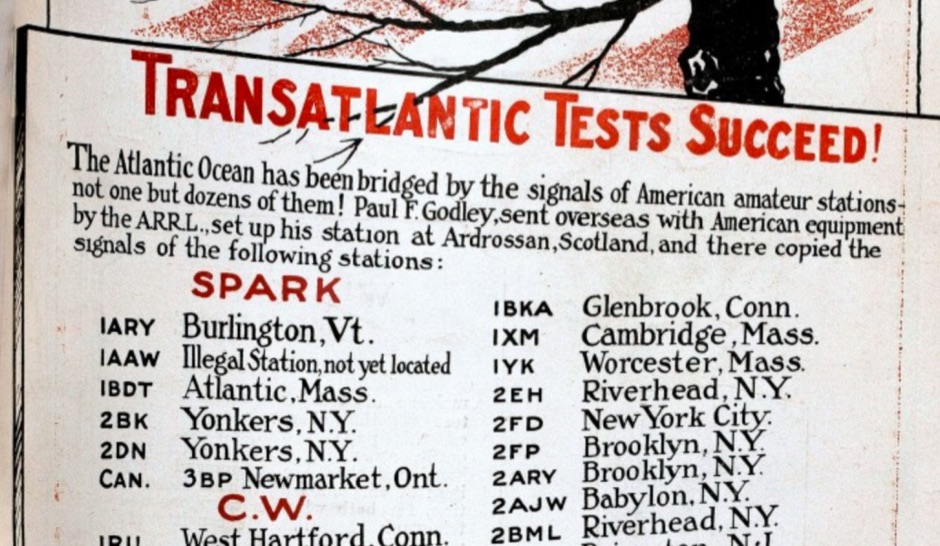 From 1921 to 1924, radio amateurs experimented with transmitting across the Atlantic. Everyday Engineering magazine organized the first sending test with English amateurs prepared to listen for signals from the US
 -
 In 2004, 2005 & 2006, after many years of very successful multi operator county expeditions, Jim (W6KC) did single operator expeditions to Mono County.
 -
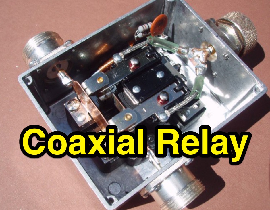 Build a SPDT coaxial relay that can be used as a main Transmit/Receive relay or an A-B switch to select between two different 6m antennas
 -
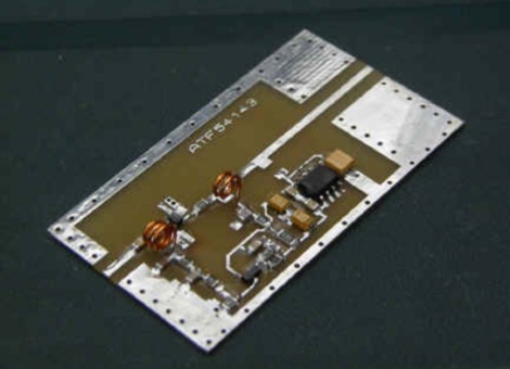 The prototype for this amplifier was originally designed for 70cm and was used on the 2004 3B9C Dx-pedition to Rodriguez Island for satellite and EME. It had a noise figure of 0.49dB with an associated gain of 20dB.
 -
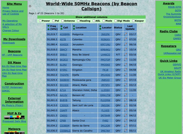 World-Wide 50MHz Beacons database maintanied by G0LGS provide a fully sortable table available also in a google map format
 -
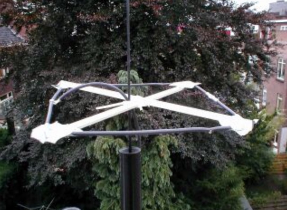 Sort of similar to the one of the 6m omni. Instead of using twin-lead, this design makes use of a more or less regular double bazooka antenna (coaxial dipole). Your attention shall be drawn to the available standart literature, such as Rothammel. In order to "compute" the dimension, Karl Rothammel mentioned that the total length of the dipole shall be 95% of the free-space wavelength. The short-circuit bridges (closing the folded dipole) are to be placed at a distance-fraction being equal to the velocity factor of the coax cable used, which will be 66% using RG-58 or RG174.
 -
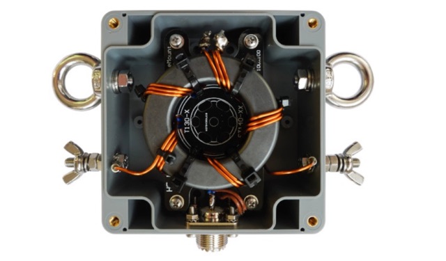 This Guide helps you to build the 1:2 BalUn 600 Watts DIY kit step by step. If a delta-loop or quad-loop antenna is powered with a coax cable from the transceiver it is necessary to use a 1:2 BalUn. This 1:2 BalUn uses a symmetrical 1:2 impedance transformer.
 -
 1296Mhz EME Station from Japan, includes eme amplifiers pictures
 -
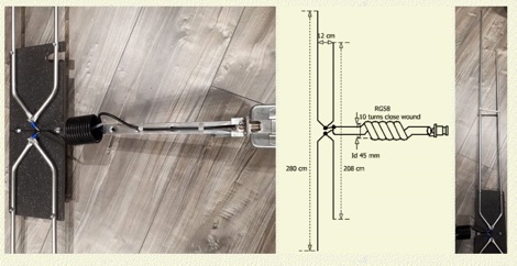 The two dipoles are parallel with a distance of 12 cm and are also fed in parallel. The total length of the 4 m dipole is 208 cm and the 6 m dipole is 280 cm.
 -
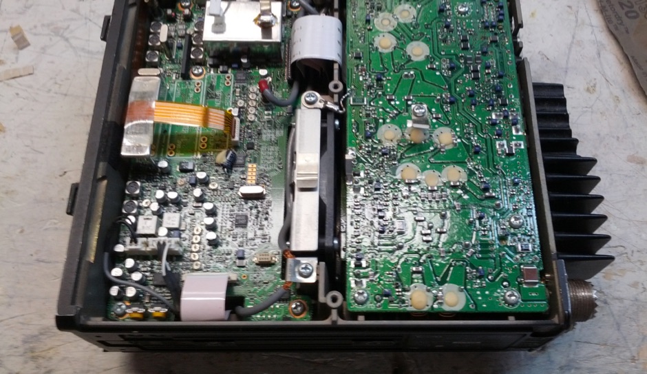 Icom 706MkIIG Filters, Make a narrow CW filter work in SSB for the digital modes
 -
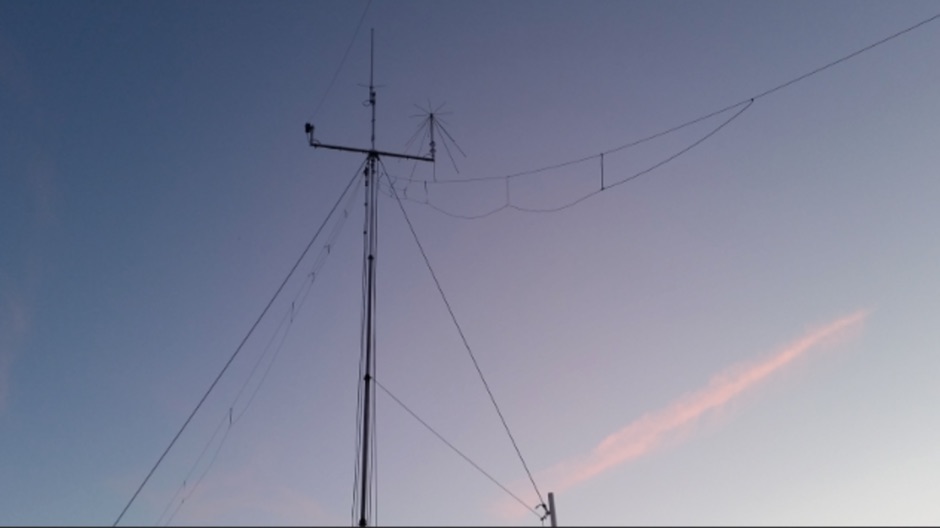 A fand dipole antenna home made for the 7,14,50 MHz. This article descbribes how to homebrew the antenna, hot to setup and some SWR measurements.
 -
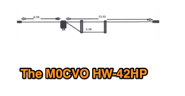 A multi-band off centre fed dipole, designed to operate on all bands from 40m (7MHz) to 6m (50MHz). Author claims it will operate on 40, 30, 20, 17, 15, 12 and 10m without an ATU (SWR <3:1) plus 6m with an ATU.
 -
 Presented is a historical collection of short-wave listening (SWL) QSL cards, primarily from the late 1930s and early 1940s, offering a glimpse into early international broadcasting and the technical pursuits of SWL operators like Les Miles during that era. The resource showcases specific QSLs from stations such as _Broadcasting Corporation of Japan_, _XGOY - The Central Broadcasting Administration_ in Chungking, China, and _Australian broadcasting ship, Kanimbla VK9MI_, each with reception dates and frequencies like 11.90MHz or 9.525MHz. It highlights the self-sufficiency of SWL enthusiasts who constructed and maintained their own radio and test equipment, evoking the sensory experience of vintage valve receivers. The collection provides concrete examples of international broadcast stations active before and during World War II, including _2RO3 - Rome_ and _WRUL - World Wide Broadcasting Foundation_ from Boston. Each QSL entry details the station, location, reception date, and often the frequency, such as 9.63MHz or 11.26MHz, allowing for historical verification of broadcast schedules. The resource also briefly mentions the operational details of the _VK9MI_ offshore radio station, directing readers to further information on its history. This compilation serves as a tangible record of global radio communication during a pivotal historical period.
 -
 DL1OFC, operating from Hankensbüttel, Germany, shares insights into the fascinating hobby of amateur radio. While the station has been on hiatus since 2016, the site provides a valuable archive of activities and technical information. DL1OFC was active across various bands and modes, including 145.225 MHz FM, 430.225 MHz FM, 29.600 MHz FM, and DMR via DB0AGM on TS-1 TG-262 DL. Shortwave operations included SSB on the 40m through 10m bands, as well as 6m. The site details regional amateur radio activities in and around Hankensbüttel, offering a glimpse into local field days and community involvement. A notable feature is Die Isetalrunde, a regional amateur radio net covering the area from the Harz mountains to the sea. The site also includes general information on radio technology, tips for obtaining an amateur radio license, and discussions on VHF/HF propagation, including specifics on the 70 MHz band.
 -
 The Tri-pole antenna, a clever modification of a standard dipole, allows for dual-band operation by integrating a third element. This design effectively shortens the overall dipole length by 10 to 20 percent, simplifying antenna rotation and offering a compact footprint. KK4OBI's article delves into the operational principles, using a 6 and 10-meter Tri-pole as a primary example, and provides comprehensive instructions for constructing any Tri-pole antenna within the 6 to 15-meter range. Key to the Tri-pole's performance is its off-center feed, necessitating a common mode choke at the feed point for optimal tuning and reduced noise. The author outlines a methodical approach to determining element dimensions, starting with a vertical element frequency calculated as 0.47 times the sum of the desired upper and lower band frequencies. This calculation, along with K-values derived from trend lines, guides the initial lengths for the horizontal arms, demonstrating how a 10m-6m Tri-pole can achieve a total horizontal length 78% shorter than a conventional 10-meter dipole. Tuning and balancing are critical, with the article detailing adjustments to arm lengths and the vertical element to achieve balanced SWR values, as validated through 4NEC2 simulations. Radiation patterns are analyzed at various elevations, showing gains around 5.7 dBi and favorable take-off angles for DX contacts. Construction details specify aluminum tubing dimensions, U-bolts, and an SO-239 connector, emphasizing the importance of a ferrite-based choke for wideband operation.
 -
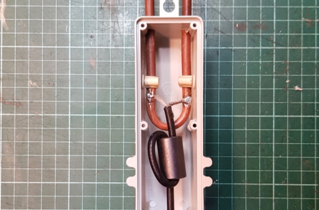 A homemade Jpole antenna for 70 cm band made with 6mm copper pipe
 -
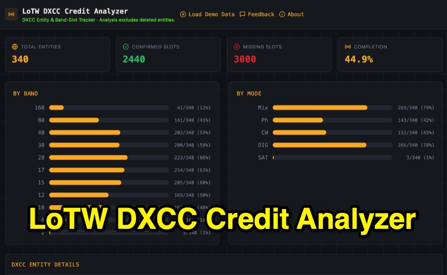 Visualizing DXCC award progress often requires manual parsing of Logbook of the World (LoTW) reports, which can be time-consuming and prone to error. This web-based utility streamlines the process by allowing hams to upload their LoTW DXCC Credit Report spreadsheet, providing an interactive dashboard for tracking confirmed entities, bands, and modes. It processes .xlsx, .xls, and .csv files, performing all calculations client-side within the browser for privacy and speed. The tool presents a comprehensive stats overview, detailing total entities, confirmed slots, and overall completion percentage. It includes progress bars for bands from _160m_ through _2m_, and modes such as CW, Phone, and DIG. A sortable DXCC Entity Details Table lists each entity, its confirmed count, and specific missing band/mode slots, with a CSV export option. Further features include a Band/Mode Matrix grid for granular confirmed status per entity, toggles for specific bands like _6m_ and _2m_, and tracking for DXCC Challenge progress across 10 eligible HF/VHF bands. It also highlights nearly complete entities and identifies most-wanted DXCC entities based on the uploaded data.
 -
 A web site maitained by KK6MK about microwave and related technical material
 -
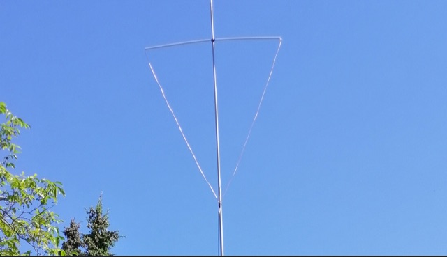 A homemade delta loop antenna for six meters band in German
 -
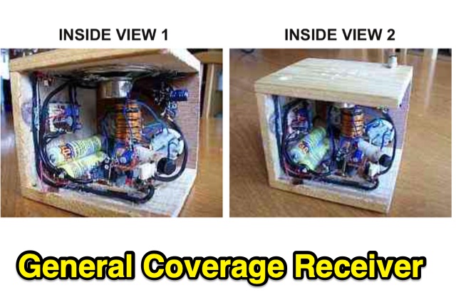 This is a compact three transistor regenerative general coverage receiver with fixed feedback. The sensitivity and selectivity is relative good, especially on the LF and MW bands, as can be expected with this simple design.
 -
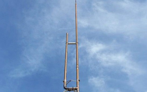 A homemade j-pole antenna for six meters band, designed to work on local repeaters, and working on the 52-53 MHz. Includes a list of needed materials and detailed description on assembling the copper tubes used to build this antenna.
 -
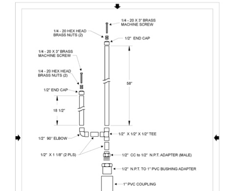 Complete plan for making a 2-meter J-Pole antenna. This drawing in PDF File includes a detailed list of the parts needed to assemble the Jpole antenna for 144 MHz.
 -
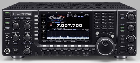 Exaustive review of the self-contained, top-performance HF/6m transceiver Icom IC-7700
 -
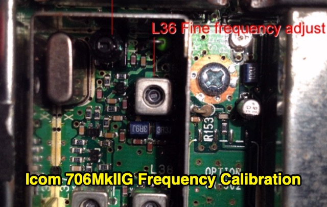 Unlike older radios, the 706 uses only one crystal oscillator (called the Master Oscillator). All other frequencies in the radio (L.O., 3-4 I.F. stages, VFO, and CW-offset) are computer-derived from the Master Oscillator. This makes it relatively simple to frequency-align the radio, so that it agrees with the Frequency Display in all modes.
 -
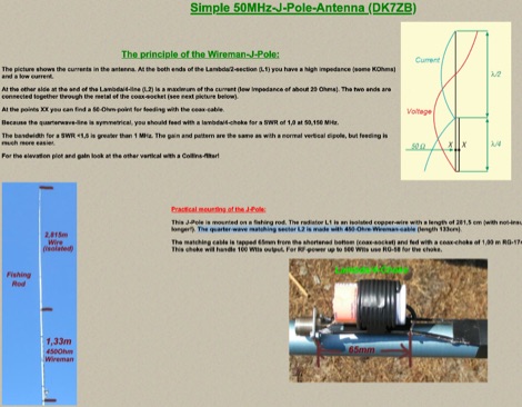 This J-Pole is mounted on a fishing rod. The radiator L1 is an isolated copper-wire with a length of 281,5 cm while the quarter-wave matching sector L2 is made with 450-Ohm-Wireman-cable
 -
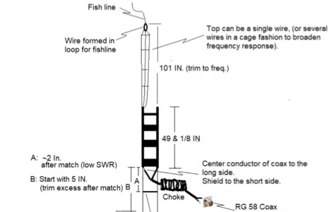 This article provides details on building a 6 Meter J-Pole antenna using PVC pipe for an enclosure. This antenna uses flat 450 ohm Window Line for the tuning stub.
 -
 Norfolk Island 6m DXpedition 25 March to 07 April 2012 VK9N/ZL1RS