Search results
Query: low bands
Links: 275 | Categories: 2
-
 Effective suppression of harmonics and parasitic radiation from HF transmitters is crucial, especially with the increasing sensitivity of VHF/UHF radio channels to interference. This project details a hybrid low-pass filter (LPF) designed to operate across the HF bands up to 51 MHz, making it suitable for 6-meter band operations while providing deep VHF/UHF suppression. The design addresses the challenge of modern interference landscapes, where even microvolt-level signals can disrupt wireless sensors and other simple VHF/UHF receivers. The filter utilizes a single elliptic link, combining high cutoff steepness with robust suppression in the hundreds of megahertz range. A key feature is the use of only two standard capacitor values, simplifying construction and component sourcing. The article provides a detailed schematic, performance characteristics, and _RFSim99_ model file, demonstrating a reflection coefficient S11 below 0.017 (VSWR < 1.03) across 1-51 MHz, ensuring minimal degradation to the antenna system. Construction notes include coil winding specifications and capacitor selection guidance, with recommendations for _FR-4_ assembly. Two capacitor sets are presented, with the first variant recommended for its lower RF current demands, keeping currents below 3 A at 1 kW passing power at 51 MHz. Fine-tuning involves adjusting frameless coils, with considerations for capacitor tolerance and high-frequency capacitance measurement accuracy.
 -
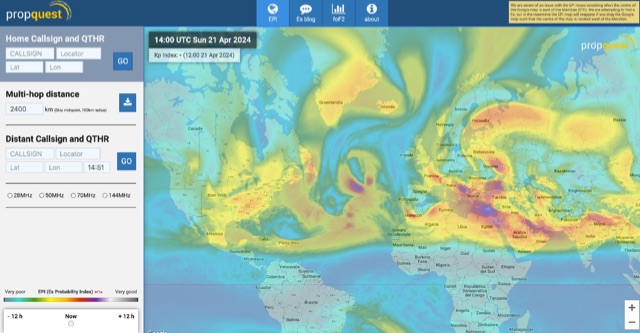 This website explains signal variations on a local radio net by tracking the foF2, a measure of ionosphere's ability to reflect radio waves. The website shows daily foF2 variations and how it affects Near Vertical Incidence Skywave (NVIS) propagation for local nets. It also considers D-layer absorption affecting lower bands and F2 MUF distance for long-distance communication. Additionally, the website tracks foEs for E-layer propagation and an EPI index for predicting Es chances.
 -
 This page provides information on how to design an Off-Center-Fed Dipole (OCFD) antenna, suitable for amateur HF bands like 80 meters or 40 meters. The antenna design allows for VSWR minima on multiple bands, making it a good choice for multi-band use. Learn how to create an OCFD antenna in either flat-top or inverted-Vee form using a single support. The page also offers tools to generate radiation patterns, VSWR charts, and antenna current diagrams for your specific antenna design, helping hams understand performance factors. Ideal for ham radio operators looking to build their own effective antennas.
 -
 Rob Conklin N4WGY delivered an informative presentation on Hexagonal Beam antennas (Hex Beams), detailing their construction, performance, and benefits over traditional multiband Yagi antennas. He highlighted their cost-effectiveness, lower wind loading, lightweight design, and multi-band capabilities without requiring traps. Conklin also discussed the improved G3TXQ design, which offers better SWR performance across ham bands. The presentation included practical construction tips, resource recommendations, and demonstrations of performance analysis tools, making it a valuable resource for both novice and experienced antenna builders.
 -
 The POCKET TUNER V1.1 is a highly compact HF T-Match antenna tuner designed for QRPp and QRP portable operations. With a credit card-sized form factor, it is tailored for low-power setups, supporting HF bands from 10m to 40m. The tuner features a unique design using rotary switches for precise capacitor adjustments, allowing tuning in small increments. Its inductance selection is optimized for various bands, ensuring efficient performance. Equipped with a resistive tuning indicator, it protects the transmitter by reducing SWR during adjustments. This versatile and portable tuner is ideal for field operations, enabling efficient antenna matching for low-power rigs.
 -
 Operating amateur radio repeaters involves understanding frequency offsets, CTCSS tones, and the basic signal flow through a repeater system. This resource details the fundamental concepts of repeater operation, including the distinction between input and output frequencies, the role of **CTCSS (Continuous Tone-Coded Squelch System)** for access, and the typical frequency bands utilized for local communication. It clarifies terms such as "simplex" versus "duplex" operation and provides a diagram illustrating the signal path from a handheld transceiver to a repeater and back to another station, emphasizing the range extension repeaters offer. The article further explains practical aspects like identifying a repeater's offset (e.g., +600 kHz for 2-meter band) and the necessity of programming the correct tone. It compares the operational benefits of using repeaters for local communication over direct simplex contacts, highlighting how repeaters overcome line-of-sight limitations. The content is structured to assist new licensees in confidently making their first repeater contacts, providing a foundational understanding of how these critical infrastructure components facilitate wider area coverage for VHF/UHF amateur radio.
 -
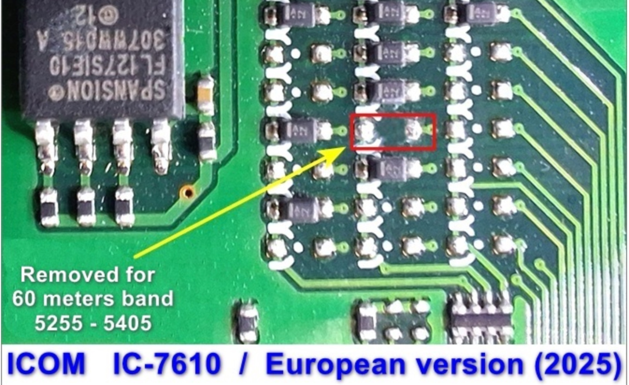 This page provides instructions for unlocking additional frequency bands on your IC-7610 transceiver to access the 60m band. The step-by-step guide is useful for hams looking to expand their operating capabilities and communicate on this popular band. By following these instructions, you can ensure that your transceiver is set up correctly to operate within the regulations of the 60m band.
 -
 This project involved designing a 7-pole Chebychev broadcast band filter to address severe interference issues caused by a new horizontal loop antenna on the KN-Q7A transceiver. The interference overwhelmed the transceiver’s front end, so a custom filter with a 3.5 MHz cutoff was built using silver mica capacitors and type 6 T130 toroidal cores. Encased in a diecast box with SO239 sockets, the filter blocks strong signals from the broadcast band, achieving over 100 dB attenuation. Tested up to 100W, it reduces interference effectively while maintaining low insertion loss across HF bands.
 -
 An FT-817 ceased transmission on the VHF 2m band, despite the other HF, UHF, and 50 MHz bands operating correctly. Suspecting an excess of input signal during FT-8 mode transmission, they conducted measurements with an oscilloscope, revealing a burnt-out PIN diode, identified as D3003, type HSU277, on the PA unit board. Following the replacement of this surface-mounted diode, their FT-817 resumed operation on the 144 MHz band.
 -
 This article from the July 1976 issue of Radio REF discusses the trend of large antennas for ham radio operators on the low bands. It specifically focuses on a Yagi 2 element antenna for the 80m band, detailing its construction and functionality. The author explains how the antenna can be switched between directing signals towards the West or East using a switch at the station. The article also provides technical details on the lengths of the director and reflector elements, and how they impact the antenna's performance. A useful resource for hams looking to build or understand Yagi antennas for the 80m band.
 -
 A full-wave delta loop antenna, approximately 141 feet in total wire length for the 40-meter band, offers a low angle of radiation, which is highly advantageous for DX operations. This design, optimized for both 30m and 40m, leverages a specific circumference calculation of 1005/F, ensuring resonance on both bands through a simple switching mechanism. The antenna's configuration enhances long-distance communication, making it a practical choice for hams with limited space. The resource details the construction process, including the use of a _Ceramic Knife Switch_ for band selection and an _RG-11_ matching section to achieve optimal impedance. It outlines the precise loop lengths required for each band, along with tuning secrets to ensure efficient operation. Requiring a minimum height of 12 feet, this antenna can be supported by a single mast or tree limb, making it suitable for suburban installations where stealth or space constraints are a factor.
 -
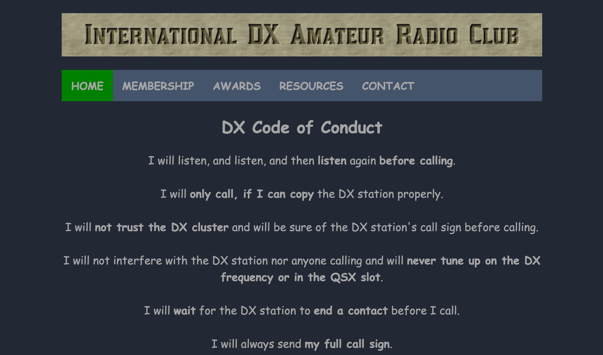 The International DX Amateur Radio Club provides a structured environment for amateur radio operators interested in long-distance communication. The club offers a variety of awards, including the DX Countries Award, DX United States Award, and DX Continents Award, among others. These awards recognize achievements in contacting stations across different geographical areas, such as Europe, Africa, South America, and Asia. The club also supplies resources like DX Spots, Grey Line Map, and Solar Data to assist operators in optimizing their communication strategies. The DX Code of Conduct emphasizes disciplined operating practices. Operators are encouraged to listen carefully before transmitting and ensure they have correctly identified the DX station's call sign. The guidelines advise against interfering with ongoing communications and stress the importance of patience, such as waiting for the DX station to complete a contact before calling. Operators are reminded to send their full call sign and avoid continuous calling, maintaining respect for fellow operators to foster a cooperative amateur radio community. DXZone Technical Profile: DX Awards | DX Code of Conduct | Grey Line Map
 -
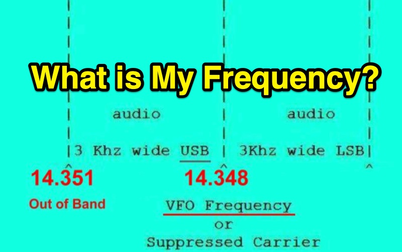 Single Sideband (SSB) operation requires careful attention to the relationship between a radio's displayed frequency (suppressed carrier) and the actual 3 kHz wide audio signal. This resource clarifies how Upper Sideband (USB) and Lower Sideband (LSB) signals occupy spectrum above or below the indicated frequency, respectively. It provides practical examples for General Class operators on the **20m** and **40m** bands, such as setting a VFO to 14.226 MHz for USB on 20m or 7.178 MHz for LSB on 40m, to maintain a safe margin from band edges. The resource emphasizes the critical importance of staying within allocated band limits to prevent out-of-band emissions, particularly when operating close to band edges. It includes relevant excerpts from **FCC Regulation Part 97**, specifically section 97.307, which details emission standards, necessary bandwidth, and spurious emission attenuation requirements. The text explains that unused sidebands are considered spurious emissions and notes that modern HF equipment typically exceeds the 43 dB spurious emission reduction standard, often achieving 60 dB or more.
 -
 This is a theoretical look at propagation on 630-Meters and 2200-Meters using ray tracing software. It expands on the brief discussion in the ARRL Handbooks. The Earth's magnetic field affects 630-Meter and 2200-Meter band propagation. Lower ionization reduces absorption, aiding low-frequency propagation. Differences exist between bands, limited daytime sky-wave propagation. Sunrise/sunset show promise, yet mechanisms are unclear. Ducting possible at night in specific conditions. Negative ions enhance propagation. Inefficient antennas and high man-made noise are anticipated. Groundwave propagation is significant on 2200-Meters.
 -
 This article explores Beverage antennas, a type used for low-frequency radio reception. Despite the mystique, they are relatively simple wire antennas placed near the ground. Their key benefit is improved signal-to-noise ratio by rejecting unwanted signals. While lengthier antennas offer better reception, even shorter versions (around 200 feet) can improve DX reception compared to traditional antennas.
 -
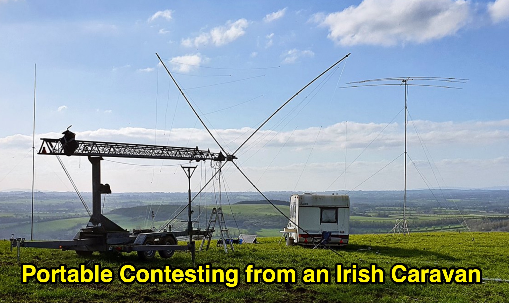 This blog chronicles over a decade of portable HF contesting from rural Ireland (2008–2019) by Olivier, operating under callsigns EI/ON4EI, EI8GQB, EI1A, and EI7T. Using only green energy from a caravan, he achieved top-tier results in major international contests—including 1st World in the 2018 IARU HF Championship (SSB LP) and multiple 1st-place finishes in CQ WW and CQ WPX SSB Europe. Operating in the demanding Single Operator All Band Low Power and SO2R categories, he deployed up to five antennas across five bands, often in remote or emergency-style conditions. The narrative blends technical detail, fieldcraft, and personal reflection, documenting triumphs, setbacks (including carbon monoxide poisoning), and the logistical challenges of sustainable portable operation—culminating in his decision to transition to team-based contesting and future DXpeditions.
 -
 The Olivia digital mode, a **Multi-Frequency Shift Keying (MFSK)** radioteletype protocol, is specifically engineered for robust communication under difficult propagation conditions on shortwave radio bands from 3 MHz to 30 MHz. Developed by Pawel Jalocha in 2003, Olivia signals can be decoded even when the noise amplitude exceeds the digital signal by over ten times, making it highly effective for transmitting ASCII characters across noisy channels with significant fading and propagation phasing. Early on-the-air tests by Fred OH/DK4ZC and Les VK2DSG on the Europe-Australia 20-meter path demonstrated intercontinental contacts with as little as one-watt RF power under favorable conditions. Common Olivia modes are designated as X/Y, where X represents the number of tones and Y is the bandwidth in Hertz, with examples including 8/250, 16/500, and 32/1000. The resource clarifies that Olivia, unlike some other digital modes, produces a constant envelope, allowing RF power amplifiers to achieve greater conversion efficiencies and making it less prone to non-linearity. Operators are advised that **Automatic Level Control (ALC)** can be set higher than no meter movement for MFSK modulation, as long as it's not driven past its high limit, contrary to common misinformation about other digital modes. The Olivia community encourages voluntary channelization on suggested calling frequencies, such as 14.0725 MHz for 8/250, to facilitate initial contacts, especially for signals below the noise floor. The Olivia Digital DXers Club provides links to Groups.io, Facebook, and Discord for community engagement and offers details on QSO parties.
 -
 This resource presents a non-rigorous evaluation of the front-to-back (F/B) ratio of short Beverage antennas, specifically designed for low-band operation on frequencies such as 160, 80, 40, and 30 meters. The author, VE1ZAC, details the methodology used to measure the F/B ratio, which involves using a Millen Grid Dip Oscillator as a portable signal source. Measurements were taken by switching the antenna direction and recording S Meter and preamp readings to derive gain numbers. The document discusses the challenges faced in achieving accurate measurements and the assumptions made during the process, such as the calibration of S Meter units at 6 dB. This evaluation is particularly relevant for amateur radio operators interested in antenna performance on low bands.
 -
 Provides access to a robust DX cluster node, G6NHU-2, running DX Spider software, which facilitates real-time amateur radio contact spotting across HF bands. This service is engineered for high reliability and low latency, ensuring rapid dissemination of DX spots from a global network of interconnected nodes. It features multiple redundant links to prevent data loss and maintain continuous operation, even if individual connections drop. The cluster integrates directly with the Reverse Beacon Network (RBN), allowing users to enable or disable skimmer spots for specific modes like CW, RTTY, FT8, and FT4. It also offers an extensive one-year spot history, significantly longer than most other DX clusters, which typically retain only a month of data. The node supports various lookup commands for callsign information, beam headings, QSL routing, and FCC database lookups, enhancing operational efficiency for DXers and contesters. Additionally, it permits self-spotting, a feature increasingly relevant in modern contests, and provides detailed instructions for connecting popular logging software such as N1MM+, HamRadioDeluxe, MacLoggerDX, LOG4OM2, Logger32, and N3FJP's Amateur Contact Log.
 -
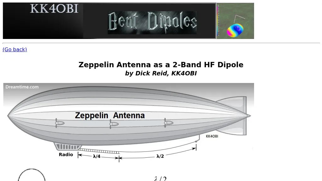 The Zeppelin antenna, a J-type design, is presented as a two-band HF dipole, offering independent operation on harmonically related frequencies. This resource details its electrical configuration, comprising a half-wave radiator end-fed by a quarter-wave matching section, and explores its historical evolution from early Zeppelin airship applications to modern amateur radio use. The article specifically examines how a Zepp antenna tuned to 28.4 MHz (10 meters) exhibits a harmonic relationship with 15.4 MHz (20 meters), noting a frequency ratio of approximately 1.84:1, which deviates from a perfect 2:1 due to factors like elevation, wire separation, velocity factor, and end-effect. Antenna modeling results, including SWR sweeps at 28.4 MHz (1.1 SWR) and 15.4 MHz (1.6 SWR), are provided through Graph 1 and Graph 2, illustrating the antenna's performance across these bands. Current distribution patterns for both the 28.4 MHz (second harmonic) and 15.4 MHz (first harmonic) operations are visually represented in Figure 2 and Figure 3, respectively. The author also includes a 4NEC2 model's "Symbol Conversion file" definitions and calculated #14 wire dimensions for achieving resonance at 28.4 MHz, with the antenna positioned at a height of 33 feet. The discussion further highlights the antenna's versatility, suggesting its potential as a single-band, center-fed, 15.4 MHz half-wave folded end dipole when fed at a specific low current point. This analysis provides practical insights into constructing and optimizing a multi-band Zepp antenna for HF operations, emphasizing its unique harmonic characteristics and physical compactness.
 -
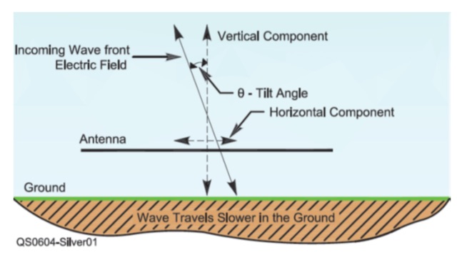
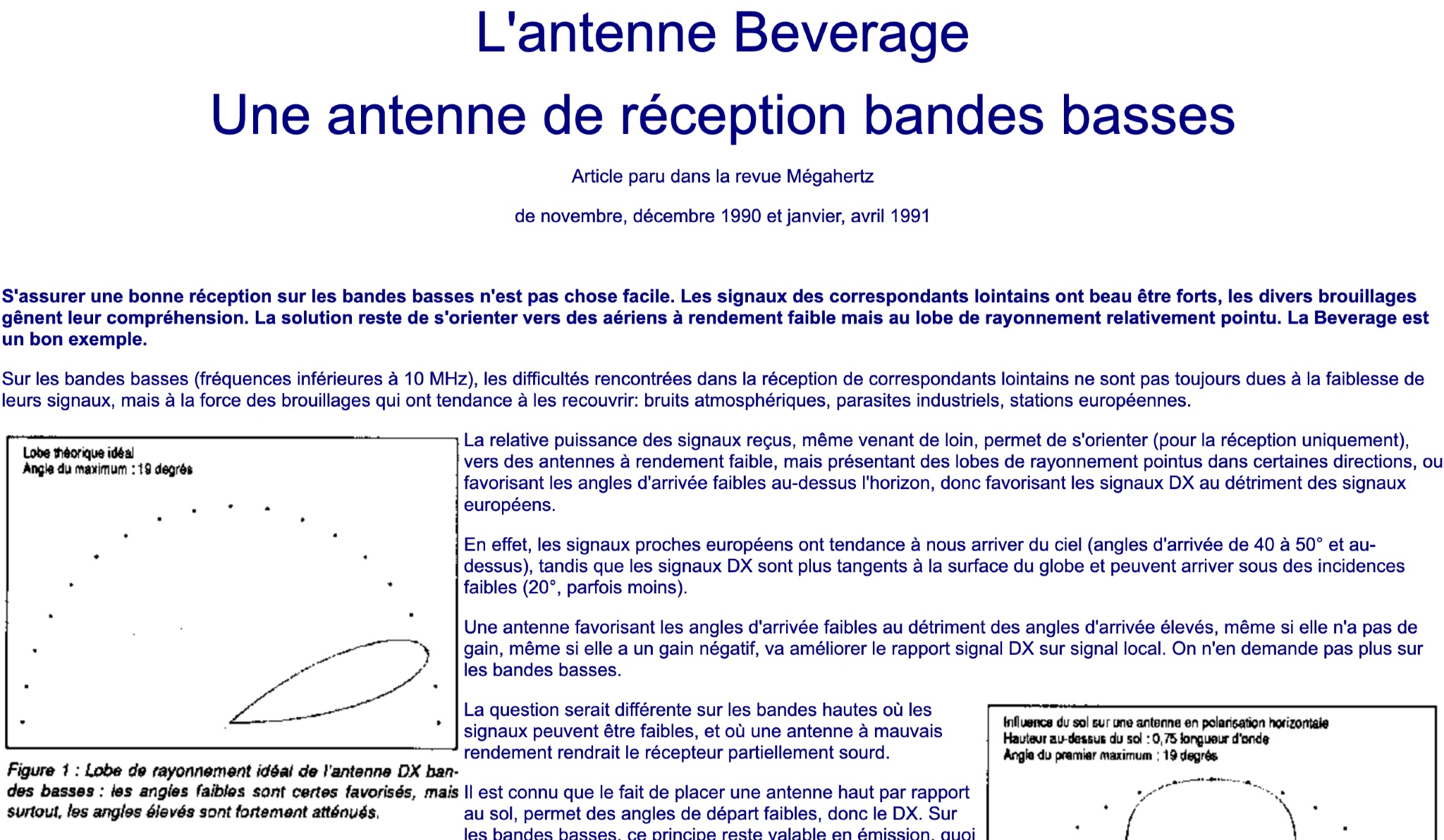 This article discusses the Beverage antenna, a reception antenna for low bands, originally published in the Megahertz magazine between November 1990 and April 1991. It explains the challenges faced in receiving signals on low bands due to interference and how the Beverage antenna's directional radiation pattern can help improve reception of distant stations. The article highlights the importance of choosing antennas with low efficiency but sharp radiation lobes for better DX signal reception. It also compares the reception characteristics of signals from European stations versus DX stations, emphasizing the benefits of antennas favoring low arrival angles for DX signals on low bands.
 -
 Demonstrates the construction of an active loop converter specifically designed for the Low Frequency (LF) bands, addressing common localized noise interference in LF reception. The design integrates a sharply tuned circuit and a tuned loop antenna, utilizing the loop as the sole tuned inductive element. By applying positive feedback, the converter significantly increases the loop's effective Q, achieving factors between 1000 and 2000, which sharpens tuning and reduces noise. The circuit employs an _NE602_ mixer stage, feeding its output to an HF receiver, with a crystal-locked local oscillator at 4 MHz. A 20-turn, 0.8-meter square loop antenna with 500 uH inductance is detailed, connected via 2 meters of figure 8 flex cable. The converter offers three selectable frequency bands: 195-490 kHz, 150-220 kHz (including the New Zealand amateur band), and 128-160 kHz (covering the European amateur band). Performance measurements indicate an effective 3dB bandwidth of approximately 100 to 200 hertz at 200 kHz. The article provides insights into component selection, including an _LF353_ op-amp and a trifilar wound transformer on a ferrite core. Sensitivity figures are presented, showing 7.5 uV of converted output per 1 uV/meter signal strength into a 50-ohm load, or 37.5 uV into an _FRG7_ receiver, highlighting its capability to extract weak signals from noise.
 -
 This page discusses the construction and use of a low pass filter for MF/LF reception, specifically for the 630 meter and 2200 meter bands. The author, KA7OEI, shares technical insights and practical advice related to amateur radio, with a focus on improving reception in the low-frequency bands. This resource is useful for hams interested in building their own filters to enhance their MF/LF reception capabilities.
 -
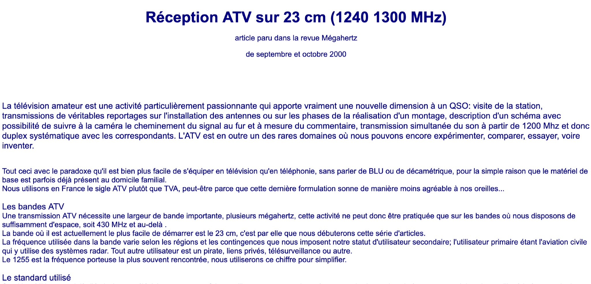 Learn about Amateur Television (ATV) on the 23 cm band (1240-1300 MHz) in this article from the September and October 2000 issue of Mégahertz magazine. Discover how ATV adds a new dimension to QSOs by allowing hams to visit stations, transmit real reports on antenna installations, follow signal paths on camera, and have simultaneous sound transmission. Explore the world of ATV experimentation, comparison, and innovation, made easier by existing equipment in many ham radio operators' homes. Find out about the ATV bands, bandwidth requirements, and the 23 cm band as a starting point for ATV activities.
 -
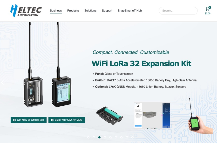 Heltec Automation specializes in the production of _ESP32-based_ LoRa development boards, wireless modules, and gateways, catering to various amateur radio applications. The product line includes devices suitable for _APRS LoRa trackers_, Meshtastic nodes, and general long-range, low-power RF projects, providing hardware solutions for digital communication experimentation. The company's offerings support diverse wireless protocols such as LoRa, LoRaWAN, Meshtastic, and Wi-Fi HaLow, enabling users to build custom communication systems. Specific products like the _Wireless Stick Lite_ and various Heltec LoRa boards are designed for integration into DIY projects, facilitating rapid prototyping and deployment of wireless solutions. Heltec provides detailed product specifications, documentation, and community support, which assists hams in leveraging their hardware for packet radio, digital modes, and IoT applications within the amateur bands. The focus remains on versatile, programmable modules that bridge traditional amateur radio interests with modern wireless technology.