Search results
Query: 6 element
Links: 598 | Categories: 3
-
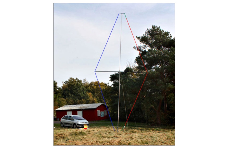 A simple and awesome wire monoband antenna, very usefull for portable and dxpeditions usage, consist of two elements, a driver and the reflector. This endfed halfwave gives a very low take off angle and is very suited for chasing DX.
 -
 The resource presents a detailed schematic for constructing a dual-band vertical antenna, specifically designed for operation on the 2-meter and 70-centimeter amateur radio bands. It illustrates the physical layout, critical dimensions, and component placement necessary for successful replication. Key elements such as the radiating elements, phasing sections, and feed point are clearly depicted, providing a visual guide for radio amateurs undertaking a homebrew antenna project. The diagram specifies the lengths for the VHF and UHF sections, indicating how these elements are integrated to achieve dual-band functionality from a single coaxial feedline. It also implies the use of common materials readily available to most experimenters, focusing on simplicity and effectiveness in its design. The visual format of a GIF image ensures direct access to the construction details without requiring extensive textual interpretation. This schematic serves as a practical reference for hams interested in building a compact, efficient vertical antenna for local and regional FM communications, offering a proven design for immediate implementation.
 -
 A 2-meter Moxon beam antenna, designed for the _144 MHz_ band, is detailed, originating from a desire to participate in the PW 2m QRP contest. The design, based on a Moxon Rectangle, offers a compact directional solution for VHF portable operations. The author, G0KYA, constructed the antenna using readily available materials like 15mm plastic conduit for the frame and 1.5mm copper wire for the elements. Initial testing with an MFJ-259B antenna analyzer showed a **1.2:1 SWR** at 144.300 MHz, indicating good resonance. The antenna's compact size, approximately 70cm x 40cm, makes it highly suitable for portable QRP work, providing a significant advantage over an omnidirectional vertical. The project includes practical advice on element spacing and construction techniques, emphasizing ease of assembly for field deployment. Field results from a local hilltop demonstrated the Moxon's directional characteristics, allowing for effective nulling of local noise and improved signal reception from specific directions.
 -
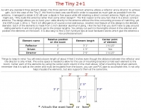 Similar to Tiny 2 but this three element direct connect antenna utilizes a reflector and a director to achieve gain.
 -
 A 4 element addition for 10m to an existing 4 element yagi (ZX antennas)
 -
 Presents a QRP AM/CW transmitter project specifically designed for the 10-meter band, utilizing a crystal oscillator and a collector-modulated AM oscillator. The design employs a 2N2219(A) transistor in a Colpitts configuration, generating 100 to 350 mW of RF output power depending on the 9-18 Volt supply voltage and modulation depth. Frequency stability is maintained by a 28 MHz crystal, with fine-tuning possible via a Ct1 trimmer capacitor for approximately 1 kHz adjustment. The resource details the RF oscillator stage, implemented with a 2N2219 NPN transistor, emphasizing frequency stability and low power dissipation. It also covers the amplitude modulation stage, managed by a 2N2905 PNP transistor, which impresses audio information onto the carrier. Selective components (C3, C4, C7, C5) enhance voice frequencies within a +/- 5 kHz bandwidth, and modulation depth is controlled by R2 and R3. The project includes a 3-element L-type narrow bandpass filter (Ct3, L3, C10) to suppress harmonics and ensure a clean output signal. The project provides a complete schematic diagram, a comprehensive parts list including specific capacitor, resistor, and inductor values, and construction notes for the coils (L1, L2, L3). It also offers practical advice on enclosure requirements, suggesting an all-metal case or a PVC box with graphite paint for RF shielding. Operational parameters such as current draw (27mA@9V to 45mA@16V) and input impedance (50 Ohms) are specified, alongside guidance on antenna matching and the importance of a valid amateur radio license for 10-meter band operation.
 -
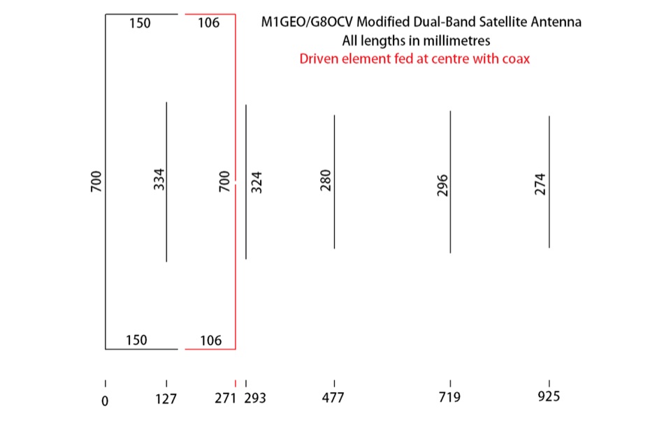 The antenna is a VHF side is a 2m moxon, tuned on 145.825 MHz. The driven element of the moxon couples to a driven element for a 5 element 70cms Yagi, tuned on 436.5 MHz.
 -
 This is a plan for a 10 elements yagi antenna for 50 mhz
 -
 Durable Easy To Build 4 Element 6 Meter Quad Or 6N2 Or 4 Element 6 And 5 Element 2 Permanent Or Portable you decide based on your needs By WA8UEG
 -
 A 6 dB gain Moxon rectangle antenna, designed for the 2-meter band, offers an excellent solution for hams seeking a compact, directional antenna for **SSB** operation, particularly in restricted spaces like an attic. This design emphasizes ease of construction using readily available materials such as 4mm OD brass tubing and plywood, making it an accessible project for many radio amateurs. The antenna's inherent characteristics, including a high front-to-back ratio of 37 dB and a 50-ohm feed impedance, contribute to its effectiveness in mitigating local noise and focusing radiated power. The project leverages the free MoxGen program for precise dimension calculations based on the desired frequency and wire size, and utilizes 4nec2 for pattern analysis, confirming a 3 dB beamwidth of 80 degrees. Construction involves bending brass tubing for the driven and passive elements, mounting them on an 800 x 350 mm plywood boom, and securing them with cable clips and epoxy resin. Initial SWR measurements at 144.3 MHz showed 1.6:1, which improved to 1.3:1 at 145.3 MHz across a flat band from 144.1 MHz to 145.5 MHz after adding a **coaxial choke** to mitigate common mode current.
 -
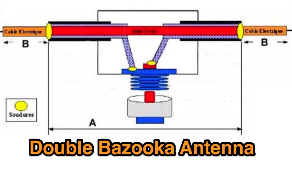 A page in french dedicated to the double bazooka antenna, with a short history of this antenna model and main characteristics including a comparison versus the dipole antenna and formulas to determine elements size.
 -
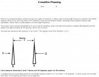 Phased antennas elements use radiated fields from multiple elements to produce nulls.
 -
 Filter design software. A program designed to expedite the design and analysis of lowpass (and highpass) filters with nearest 5% component values. SVCfilter is 32-bit Windows electrical filter design software nicely written to help the radio amateur, technician or engineer design and analyze lumped-element lowpass and highpass filters.
 -
 Demonstrates the construction and implementation of a **two-element phased vertical array** for 40 meters, utilizing _Christman phasing_ techniques. The author, W4NFR, details the process from building individual 1/4-wave aluminum verticals to integrating them into a phased system. The resource covers antenna spacing of 32 feet, elevated radial design, and the critical steps for tuning each vertical to achieve a 1.1:1 SWR before combining them. It also provides insights into calculating precise coax lengths for feedlines and the phasing delay line, emphasizing the use of an MFJ-269 Antenna Analyzer for verification. The finished system exhibits good front-to-back nulls, with an overall SWR ranging from 1.6:1 to 2.2:1, which is managed by an antenna tuner. The project includes detailed photos of the relay box, showing 12 VDC relays capable of handling 5KV, and the control box in the shack for switching between three different antenna pattern configurations. Static bleed-off chokes are incorporated for protection, and the construction emphasizes robust weatherproofing for outdoor elements.
 -
 This project details the construction of a **full-sized 40-meter vertical antenna**, born from a renewed interest in 7 MHz operation and a desire for improved effectiveness over simple dipoles. The author, K5DKZ, initially focused on VHF experimentation, which provided an inventory of aluminum tubing and fiberglass spreaders for this endeavor. Before this vertical, K5DKZ utilized an 80/40 meter inverted-vee trap dipole and a 40-meter broadband dipole, but now primarily uses a pair of full-sized, phased, quarter-wave verticals spaced 35 feet apart for serious 40-meter work. The construction involves a base-heavy design for stability, using a 44.5-inch section of 1-1/4 inch steel TV mast driven into 1-3/8 inch aluminum tubing, insulated by a 105-inch section of Schedule 40 PVC pipe. The assembly reaches 31 feet, close to the 32 feet required for a quarter-wavelength on 40 meters, with fine-tuning achieved by winding wire onto a fiberglass spreader. The design is explicitly presented as a foundation for a two-element 40-meter Yagi beam, outlining modifications like substituting aluminum for steel in the base and using an inductive hairpin match for the driven element. The article also discusses tuning considerations for a large 40-meter beam, noting the 100 to 200 kHz upward frequency shift when raised, and suggesting methods for installation on a tower. The author emphasizes the cost-effectiveness and good performance of the monopole approach, especially when multiple verticals are needed.
 -
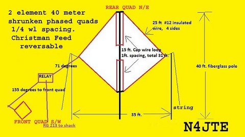 A 2 element small footprint 40 meter phased, reversible, downsized quad array antenna.
 -
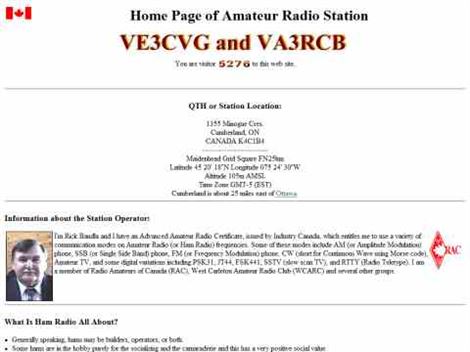 VE3CVG 222 MHz (1.25m) 6 element plumber's delight yagi antenna
 -
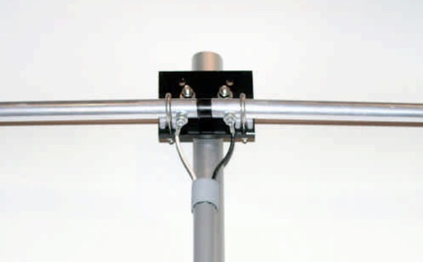 Design and build an 6 m dipole antenna from aluminum, tubing, that resembles the active element of a yagi beam antenna.
 -
 The Elecraft K2 transceiver requires specific modifications for optimal soundcard digital mode operation, particularly for PSK31. The original article, circa 2001, details initial challenges with manual PTT and speech compression settings. A key modification involves adding headphone audio and a compression disable signal to the K2's microphone jack, utilizing pins 4 and 5. The **COMP0** signal, active low, is shorted to ground via a non-inverting open collector switch circuit, comprising two resistors and two transistors, mounted on the SSB board near U3. This circuit provides effective control of an analog signal line with good noise immunity. The switchbox itself repurposes a computer COM port switch, using only two of its original connectors and four of the nine poles. It integrates a microphone preamplifier, a PTT circuit built with 'flying leads' construction, and RCA jacks for soundcard connections. A trimpot adjusts the audio drive to the K2. The central DB9 connector links to the K2's mic connector via a shielded RS232 serial cable, ensuring proper grounding and signal routing. An external footswitch PTT jack is also included. Further enhancements include a **noise-canceling microphone** preamp based on a QST December 2000 article, adapted for Heil mic elements. This preamp, built with pseudo-Manhattan style construction, provides a gain of approximately 2 by changing emitter resistors (R9 and R16) from 680 ohms to 330 ohms. A 10-ohm series resistor and 47 µF capacitor on the +5V supply mitigate noise spikes.
 -
 The design and feeding of driven elements for VHF/UHF Yagi antennas , modeling, observations and some case studies by Graham Daubney F/G8MBI
 -
-
 Demonstrates the adaptation and construction of a 7-element DK7ZB Yagi antenna for the 4-meter band (70 MHz), utilizing components from a defunct 2-meter CUE DEE Yagi. The resource details the modifications made to the original DK7ZB design to fit the shorter CUE DEE boom length, specifically adjusting element lengths for 6mm rod elements while reusing existing mounting holes for the reflector and last director. It provides precise element lengths for the reflector, dipole (12mm aluminum tube), and five directors, along with a note on cutting elements for transport. The article includes a 4NEC2 simulation file for performance analysis and an SWR plot, confirming the antenna's electrical characteristics. It also specifies the calculation for the quarter-wavelength matching cable using SAT752F coaxial cable, resulting in a 909mm length. Practical application is shown with the finished antenna in operation at JO20XC, listing several activated Maidenhead squares such as JO56PA and JP40KS, validating its effectiveness for portable 70 MHz operations.
 -
 This PDF document details the construction of a **70 MHz** Big Wheel antenna, a horizontally polarized omnidirectional array. The design utilizes three full-wave loops, each approximately **2160 mm** in diameter, arranged in a triangular configuration. The resource provides mechanical dimensions for the antenna elements and a comprehensive bill of materials, specifying component quantities and types, such as M8 stainless steel bolts, 15x15x1.5 mm square aluminum tubing for spacers, and 8 mm aluminum rod for the arcs. The central hub is constructed from two 160x160x8 mm aluminum plates, with four 40 mm long polyamide insulators supporting the radiating elements. The feed system incorporates a 50 mm diameter aluminum pipe for mounting and a matching stub constructed from a 120x20x2 mm aluminum sheet, connected via M8x10 mm bolts. The resource includes a diagram illustrating the mechanical dimensions and assembly points, including the N-connector fixing point and the center conductor attachment. The project was published on May 25, 2011, by Peter OE5MPL and Rudi OE5VRL. DXZone Focus: PDF | 70 MHz Big Wheel | Mechanical Dimensions | **2160 mm** loop diameter
 -
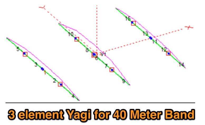 An homebrew project for a 3 element coil-loaded Yagi beam antenna for 40 Meter band
 -
 5-element antenna, with which G0JJL has worked lots of EU crossband, and won the RSGB Christmas Cumulatives 70MHz section twice in a row.
 -
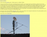 A 5 elements homemade DK7ZB yagi antenna for 4 meters band based on a 50MHz TONNA
 -
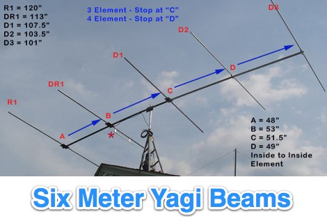 Article describing how to homebrew a yagi antenna for 50 MHz, includes plans for a four and five elements yagi beam and details how how match impedence with a gamma match
 -
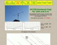 This Duoband-Yagi has a boom of 3.60 m and 3 elements for 10 m 4 elements for 6 m and one feedpoint with 50 Ohm
 -
-
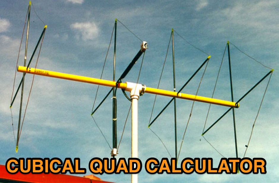 An online javascript calculator for cubical quad antennas, simply input the resonating frequency to calculcate up to a five element quad antenna. This quad antenna calculator let you determine the total length of each element and spacing among elements.
 -
 The 10-minute, 25-second video demonstrates making a QSO via the VO-52 amateur radio satellite, focusing on real-time Doppler shift correction. It features Simon, 2E0HTS, operating a Yaesu FT-847 transceiver and a homebrew dual-band Yagi antenna, specifically a 10-element 435 MHz Yagi for uplink and an IO Loop for 145 MHz downlink. The video visually details the operator's technique for continuously adjusting the uplink frequency to compensate for the satellite's changing velocity relative to the ground station, a critical aspect of successful satellite communication. The demonstration highlights the practical application of Doppler compensation, showing the operator tuning the transmit frequency to maintain a stable received signal from the satellite. This approach contrasts with systems employing automatic Doppler correction or full-duplex operation, providing insight into manual frequency management for satellite passes. The video serves as a direct, observational guide for hams interested in LEO satellite operations, particularly those using non-tracking, manually tuned setups.
 -
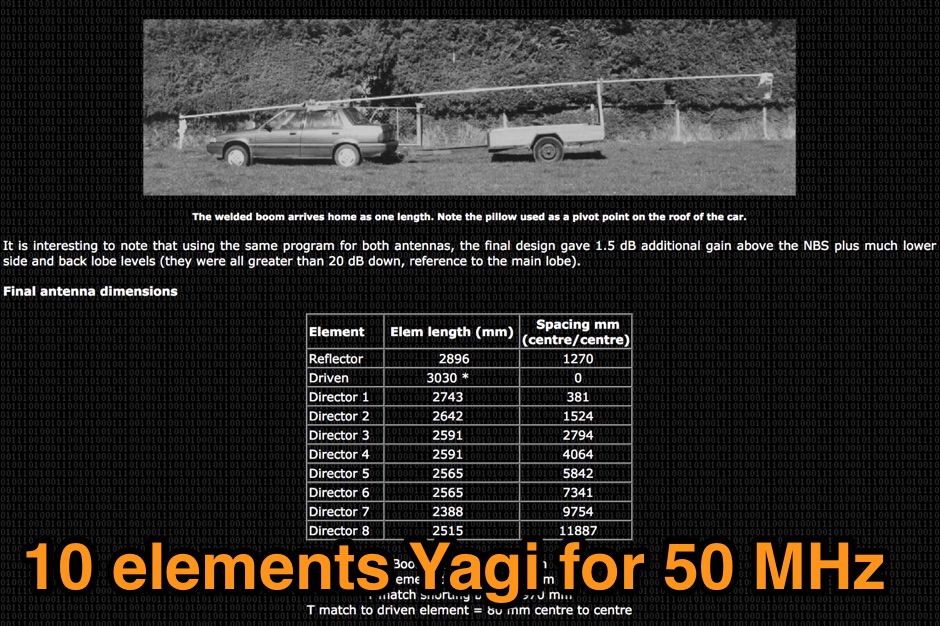 A homemade 10 element Yagi Beam Antenna for 50 Mhz by Rod Mackintosh, a NBS Yagi on a 13.2 metre boom.
 -
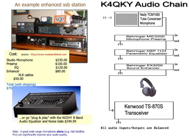 Enhanced SSB Audio (ESSB) is a specialized operating mode that extends the capabilities of traditional Single Sideband (SSB) voice transmissions. This presentation by K4QKY delves into the technical aspects of ESSB, discussing its advantages and the ongoing debates within the ham radio community regarding audio quality and bandwidth usage. ESSB aims to provide clearer and more natural-sounding audio, which can enhance the overall communication experience for operators. The presentation covers various topics, including microphone selection, audio processing techniques, and the importance of proper equalization. It also addresses the controversies surrounding ESSB, such as the potential for interference and the debate over whether it strays too far from traditional SSB practices. By understanding these elements, amateur radio operators can make informed decisions about their audio setups and contribute to discussions about the future of SSB operations.
 -
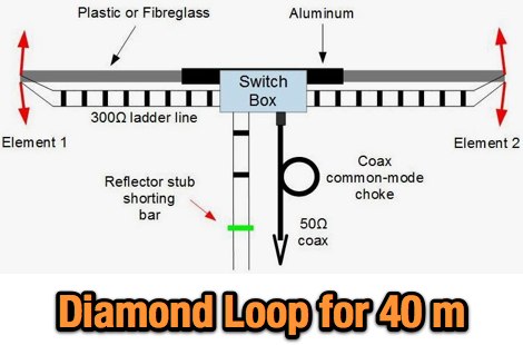 A 2 element Narrow Diamond Loop Array for 40 Meters by VE3VN
 -
 Ground Plane - 1/4 wave vertical, J-Pole, 3 Element Yagi Beam and simple antenna supports
 -
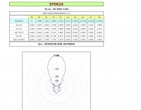
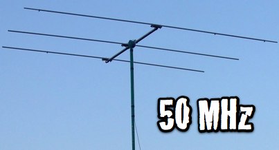 EF0603S is a 3 element portable yagi antenna for six meters band by YU7EF
 -
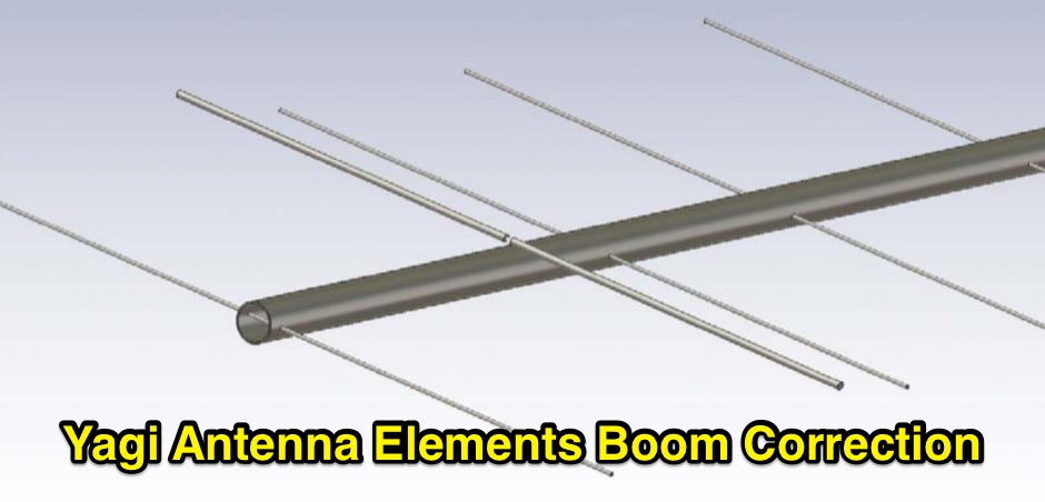 Dragoslav Dobricic, YU1AW antennex article on influence of Boom on frequency performance and how compensate it
 -
 The Double 5/8 is a natural extension of the Single 5/8 and uses a 5/8λ element for both the top and bottom radiators.
 -
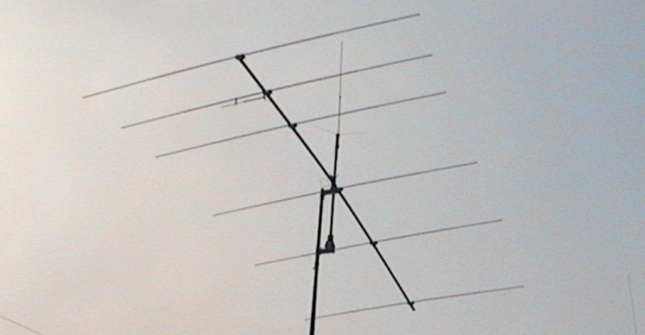 In this PDF article Zack Lau describe how to homebrew a four element yagi beam antenna for 50 MHz band, including how to build mounting blocks and tubing clamps to hold elements.
 -
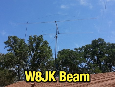 A compact 2 element W8JK beam antenna for 20M to 10M bands by AF6SA
 -
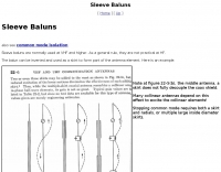 Sleeve baluns are normally used at VHF and higher. As a general rule, they are not practical at HF. The balun can be inverted and used as a skirt to form part of the antenna element
 -
 Constructing a compact, single-feed triband Moxon antenna for 20, 15, and 10 meters is detailed by DU1RZ, drawing from his personal experience with space-constrained antenna projects. Initially fascinated by cubical quads, the author transitioned to Moxon designs in 2005 after realizing his roof space was insufficient for a bulky quad. His first experimental monoband Moxon for 15 meters, built from repurposed materials, provided solid DX QSOs for seven years, despite being slightly below the 21 MHz band center. The project outlines the design process, including using the _MOXGEN Calculator_ for element dimensions and material selection, such as #14 AWG enamel copper wire and fishing poles for spreaders. DU1RZ shares insights from simulations with DL2GMS regarding insulated versus non-insulated wire performance, noting that insulated wire can shift resonant frequencies lower. The assembly instructions cover preparing wire elements, connecting feed points, and tuning the antenna, with initial SWR measurements taken at 10 feet and final readings on a mast showing excellent results: 1.0:1 on 14.225 MHz, 1.1:1 on 21.250 MHz, and 1.3:1 on 28.50 MHz. Transmission tests with 4F1BYN indicated a front-to-back ratio of approximately 2 S units with 10 watts output. The author emphasizes adaptability, encouraging builders to use readily available materials rather than strictly replicating his setup. Key observations from DU1RZ and DL2GMS highlight the antenna's strong performance across 20, 15, and 10 meters, good front-to-back ratio, full bandwidth on 20 and 15 meters, and its small turning radius of about 4.18 meters (13.54 feet), making it suitable for limited antenna space. Its lightweight construction and low wind load are also noted as significant advantages.
 -
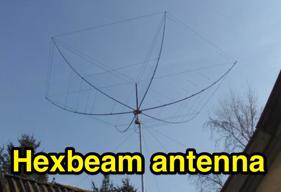 An HexBeam antenna project, a 2 full elements on six bands
 -
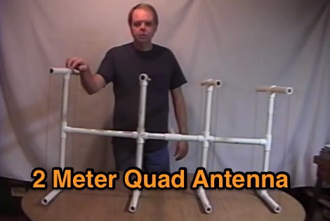 A four elements quad antenna for 144 MHz made with PVC pipes
 -
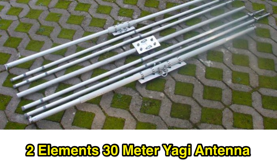 Dimensions and EZNEC plots for a 2 Element 30 meter Yagi antenna with 28 Ohm featuring 4.3 dBd Gain and a 16dB F/B with a good bandwidth.
 -
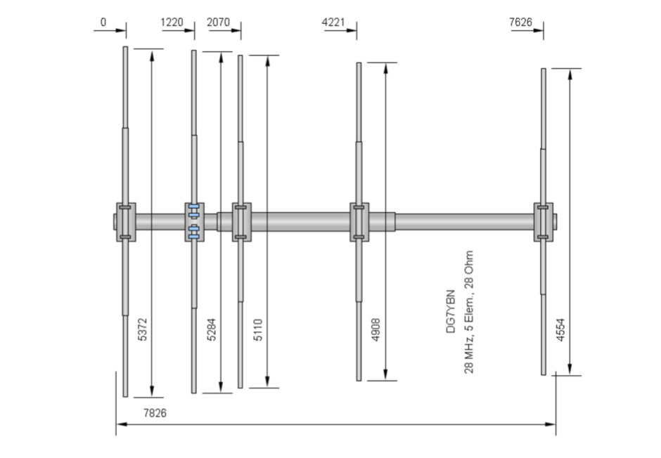 A 5 element yagi beam antenna for ten meters band with full dimentsions, eznec file and coax match informations for 50 ohms feed line
 -
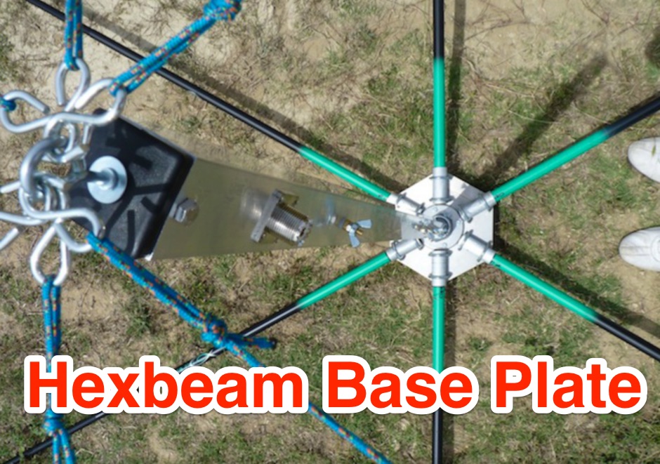 A 10mm thick aluminum plate serves as the foundation for a homemade hexbeam antenna, designed to support the central mast and six radiating elements. The construction details include precise drilling for the central mast and the six fiberglass spreaders, ensuring proper alignment and mechanical integrity. The author, FY8PE, shares insights from his experience, emphasizing the importance of robust materials for long-term outdoor deployment. The design incorporates a specific arrangement for the spreader attachment points, allowing for easy assembly and maintenance of the hexbeam's unique geometry. While specific performance measurements are not detailed, the focus on structural strength and material choice suggests an emphasis on reliability in various weather conditions. The project provides practical guidance for hams looking to build a durable hexbeam base.
 -
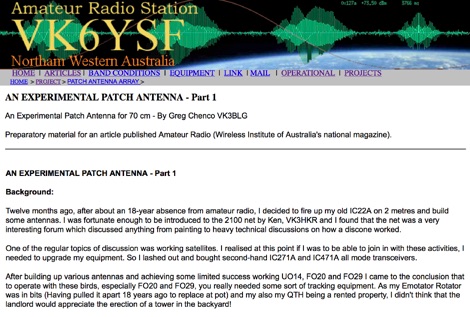 This web article by VK3BLG details the construction of an experimental 70cm (432 MHz) circularly polarized patch antenna, intended for satellite communication. The resource provides dimensions, feed point specifications, and impedance matching considerations for a single patch element, with discussion extending to array configurations for circular polarization. Construction involves a copper patch element on a dielectric substrate, fed via a coaxial cable. The design is based on information derived from AO-40 satellite antenna specifications, focusing on achieving circular polarization for satellite reception. The article includes specific dimensions for the patch and feed points, along with impedance values. Validation is implied through on-air satellite reception reports, with initial signal reports of **1 S-point above noise** for AO-40 beacons using a grid reflector, improving to **3-4 S-points above noise** with a 2-turn helical feed. The author references a _NanoVNA_ for impedance measurements and discusses the relationship between slot and dipole antennas in the context of patch design. DXZone Focus: Web Article | 70cm Patch Antenna | On-Air Satellite Reception | Circular Polarization
 -
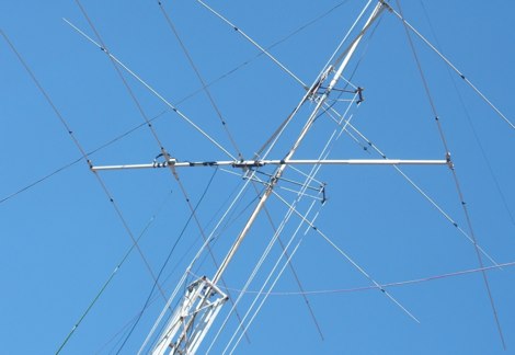 An homebrew project for a 4 elements yagi monoband antenna for the 10 meters by 9M2MSO
 -
 Examining the _Angle of Radiation_ and its impact on amateur radio operations, the resource provides insights into optimizing antenna performance for DX and local contacts. It features a design for SPOTTO, a direct conversion high-performance universal DSB transceiver, detailing its construction and operational characteristics for homebrew enthusiasts. Additionally, the site presents a 7-element VHF high-gain antenna design, offering practical schematics and expected performance metrics for those seeking enhanced gain on VHF bands. The resource also covers the development and popularity of the _FT8_ digital mode, highlighting its effectiveness in weak-signal conditions and its role in special event operations like the FT8DMC anniversary. It includes information on Hamfest India 2023 and the Lamakaan Amateur Radio Convention, providing dates and organizational details for significant Indian amateur radio gatherings. Technical articles on Direct Digital Synthesizers (DDS) VFOs and low-cost multifunctional frequency counters offer practical project ideas for radio amateurs.