Search results
Query: 40m 20m
Links: 63 | Categories: 0
-
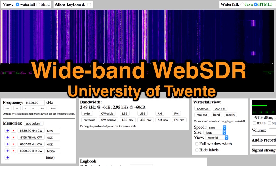 On this page you can listen to and control a short-wave receiver located at the amateur radio club ETGD at the University of Twente. In contrast to other web-controlled receivers, this receiver can be tuned by multiple users simultaneously, thanks to the use of Software-Defined Radio. Provided by PI4THT
 -
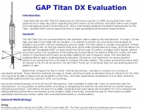 GAP Titan DX Evaluation, antenna for 10m 15m 20m 40m 80m
 -
 This multiband wire antenna it is an off centre fed dipole, with 10 feet of vertical radiator, needs no tuner on 40m, 20m and 10m and works fine on all bands above 40m with a tuner, and even below 40m on 60m, and 80m.
 -
 Multiband Center-Loaded Off-Center-Fed Dipole (CL-OCFD) antenna that work on 80m 40m 30m 20m 15m 10m. The Center-Loaded Off-Center-Fed Dipole (CL-OCFD) antenna, developed by Serge Stroobandt, offers a versatile solution for amateur radio enthusiasts, covering multiple HF bands (80, 40, 30, 20, 15, and 10 meters) without the need for an antenna tuner. This innovative design utilizes a capacitor for resonance on the 80-meter band and a resistor to manage static charges. The CL-OCFD enhances bandwidth and simplifies operation, making it a significant advancement on OCF Dipole design.
 -
 Demonstrates the construction and performance of an updated ZS6BKW multiband dipole, a variant of the _G5RV_ antenna, specifically designed for HF operation. The article details a real-world installation using 13.5m copper wire elements and 12.2m of 450 Ohm ladder line, configured as a sloping inverted-V with the apex at 10m and ends at 4m above ground. It covers the critical aspect of impedance matching, incorporating an 8-turn choke balun at the feedline transition to RG-58U coax to mitigate RF common mode current. Measurements confirm favorable SWR readings below **1.3:1** on 7.1 MHz, 14.11 MHz, 18.06 MHz, and 24.8 MHz, indicating effective resonance across 40m, 20m, 17m, and 12m bands. The installation also shows usable SWR dips on 3.55 MHz (5:1), 29.02 MHz (2:1), and 50.84 MHz (3:1), extending its utility to 80m, 10m, and 6m with an antenna tuning unit. Initial on-air results report clear reception of stations over **5000km** away, validating its DX potential.
 -
 The ZS6BKW multiband HF antenna, a design by ZS6BKW (G0GSF), functions effectively on multiple HF bands without requiring an Antenna Tuning Unit (ATU) for 40, 20, 17, 12, 10, and 6 meters. This antenna, approximately **27.51 meters** (90 feet) long with a 12.2-meter (40-foot) open-wire feeder, is a direct descendant of the _G5RV_ but offers superior multi-band resonance. It can be deployed as a horizontal dipole or an inverted-vee, with the latter requiring only a single support and maintaining an apex angle of at least 90 degrees to prevent signal cancellation. Performance data, recorded with an MFJ Antenna Analyser, indicates SWR values of 1:1 on 7.00 MHz (40m) and 14.06 MHz (20m), with SWR below 1.3:1 on 17m, 10m, and 6m. While primarily designed for these bands, the antenna can be adapted for 80m, 30m, and 15m with an ATU, preferably at the balanced feeder's base. The use of 450-ohm twin-lead for the feeder is recommended over 300-ohm for improved strength and reduced losses, especially in adverse weather conditions. This design, originally published in _RadCom_ in 1993 and featured in Pat Hawker’s "Antenna Topics," provides a compact and efficient solution for HF operation, particularly for those with limited space or resources.
 -
 F6EZX presents a detailed account of constructing a compact, multi-band _Levy antenna_ for portable holiday operations, specifically addressing issues with local QRM from a previous _Deltaloop_ setup. The article outlines the design criteria, including multi-band operation on 40m, 30m, 17m, 15m, 12m, and 10m, a symmetrical configuration to reduce interference, and a low take-off angle for DX. Construction involves 2x 10.3m radiating elements and a 15.3m open-wire feeder (ladder line) with 7cm spacing, made from 1.5mm2 copper wire and foam pipe insulation spacers. Theoretical calculations, referencing F9HJ's "_Les antennes Levy_" book, guide the determination of element lengths and feeder impedance characteristics, aiming for a good match across bands with a commercial antenna tuner. Initial field tests with the _VCI Vectronics VC300DLP_ tuner showed a 1:1 SWR from 80m to 10m, with some difficulty on 17m. The antenna, mounted as a 45-degree slopper with the high point at 12m, successfully facilitated DX contacts to South America, particularly Chile and Argentina, suggesting a lower take-off angle compared to the previous Deltaloop which favored Brazil. The Levy antenna significantly reduced TVI/RFI, attributed to its improved symmetry and greater distance from the QRA. While signal reports on 15m and 20m were 1-2 S-points lower than the Deltaloop, its performance on 40m and 30m was comparable, fulfilling the design goals for a portable, low-cost, multi-band solution.
 -
 Presents G0GSF Brian's ZS6BKW antenna, a refined iteration of the classic G5RV, offering improved performance across multiple HF bands. The design emphasizes specific radiator and ladder line lengths to achieve lower SWR on 40m, 20m, 17m, 12m, and 10m, making it a practical choice for operators seeking a single wire antenna solution. The document includes critical dimensions for the flat-top and the 450-ohm ladder line section, which are key to its multiband resonance characteristics. Unlike the original G5RV, the ZS6BKW aims for direct 50-ohm feedpoint impedance on several bands, reducing the need for an external antenna tuner. My field experience with similar optimized dipoles confirms that precise construction, particularly the ladder line length, is paramount for realizing the intended SWR benefits. This design offers a compelling alternative for hams with limited space or those preferring a less complex antenna system.
 -
 Rugged, disguised 2m, 220MHz, 440MHz, and 2m/440 dual band antennas, HF portable antennas, portable dipoles.
 -
 The 6 Band Inverted L Antenna MK3 is a versatile multiband antenna designed for amateur radio operators. This antenna covers 160m, 80m, 40m, 20m, 15m, and 10m bands, making it suitable for a wide range of HF communications. The design is based on a W3DZZ configuration, incorporating traps for optimal performance. The MK3 version features a sturdy 5/8th CB mast, replacing the original timber mast, which enhances durability against harsh weather conditions. The antenna's construction allows for effective operation, particularly on the 40m band, where it has been successfully used to contact distant locations including ZL, VK, and Antarctica. Constructing this antenna requires careful attention to detail, especially regarding the radials and grounding. The traps resonate at specific frequencies, and additional resources are available for building coaxial traps. The antenna is designed to work efficiently without an ATU on the lower bands, while higher bands may require tuning. This project is ideal for both beginner and intermediate operators looking to enhance their station with a reliable multiband antenna.
 -
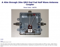 A 40m through 20m QRO End Fed Half Wave Antenna Coupler by Steve Yates - AA5TB
 -
 The Chameleon V1 HF Multiband Antenna is a mobile antenna that can also be used as portable. Lightweight mil whip antenna system with 10 BANDS capability 6m, 10m, 12m, 15m, 17m, 20m, 30m, 40m, 60m & 80m.
 -
 Simple DIY stealth apartment antenna for 20m and 40m. It is basically a ZigZag quarter wave dipole antenna
 -
 An homemade portable vertical antenna with a trap near the mid point of the main element. The trap is made with 42mm diameter PVC pipe with 9 turns of wire on it
 -
 This resource details the computer-optimized design of the _ZS6BKW_ multiband dipole, an evolution of the classic _G5RV_ antenna. It begins by referencing the original 1958 RSGB Bulletin article by Louis Varney G5RV, explaining the operational principles of the G5RV's flat-top and open-wire feedline on 20m and 40m, noting its impedance transformation characteristics for valve amplifiers of that era. The article then transitions to the rationale for optimizing the design for contemporary solid-state transceivers requiring a 50 Ohm match. The core of the project involves using computer modeling to determine optimal lengths for the flat-top and matching section, aiming for a VSWR of less than 2:1 on multiple HF bands. It discusses the process of calculating feedpoint impedance based on antenna length and frequency, referencing professional literature from Professor R.W.P. King at Harvard University. The analysis also considers the characteristic impedance (Z(O)) of the open-wire line, identifying a broad peak of adequate values between 275 and 400 Ohms. Specific design parameters for the improved ZS6BKW are presented, including a shorter flat-top and a longer matching section compared to the original G5RV, with a velocity factor of 0.85 for the 300 Ohm tape. The article confirms acceptable matches on 7, 14, 18, 24, and 28 MHz bands when erected horizontally at 13m, and also discusses performance in an inverted-V configuration, noting frequency shifts. The author, Brian Austin ZS6BKW, emphasizes the antenna's suitability for modern 50 Ohm coaxial cable without a balun.
 -
 JJ0DRC's HF multi-band delta loop antenna project, initially conceived during the waning peak of Cycle 23, addresses the common challenge of achieving effective DX operation from a small residential lot in Japan. Dissatisfied with a ground plane antenna's performance in SSB pile-ups, the author sought a beam-like solution without a tower, drawing inspiration from a JJ1VKL article in CQ Ham Radio Sep. 2000. The antenna, constructed in October 2000, employs two 7.2-meter fishing rods (37% carbon fiber, reinforced with cyano-acrylate glue and aluminum tape) and 1mm enameled wire, fed by an Icom AH-4 external antenna tuner. While the exact beam pattern remains unmeasured, JJ0DRC observed a significantly higher callback rate compared to dipole antennas, particularly on higher bands. The system's circumference length of 15-20m is crucial for maintaining a good beam pattern across HF bands, though performance on lower bands like 80m, 40m, and 30m becomes less directional as the length deviates from a full wavelength. Ongoing maintenance addressed degradation issues, including aluminum tape cracking and wire breakage at connection points due to strong winds (often exceeding 10-15m/s in winter). The author reinforced rod connections with IRECTOR PIPE SYSTEM components and INSU-ROCK ties, and improved wire attachment methods using Cremona rope and epoxy bond to enhance durability.
 -
 The ZS6BKW wire antenna, a variant of the G5RV, utilizes a specific 13m (42.6 ft) length of 450-ohm window line as its matching section, feeding a 28.5m (93.5 ft) flat-top element. This design aims for lower SWR on 40m, 20m, 17m, 12m, and 10m compared to a standard G5RV, often achieving SWR values below 1.5:1 on these bands without an antenna tuner. The feedpoint impedance transformation provided by the window line allows for direct connection to 50-ohm coax on multiple bands. F4FHH's experience involved constructing the ZS6BKW and evaluating its performance against an _OCF dipole_ (Off-Center Fed) on various HF frequencies. The article includes observations on SWR readings and operational effectiveness, highlighting the ZS6BKW's suitability for multi-band operation. The antenna's overall length, including the flat-top and window line, is approximately **41.5 meters** (136 feet), making it a significant wire antenna for fixed station use. Comparative analysis with the OCF dipole provided practical insights into the ZS6BKW's advantages and limitations, particularly concerning bandwidth and tuner requirements.
 -
 QRZCQ.com provides a centralized online platform for amateur radio operators, integrating a global callsign database with DX Cluster functionality. The service features real-time DX spotting, filtering capabilities for specific bands (e.g., 160m, 80m, 40m, 20m, 15m, 10m), and specialized filters for awards like IOTA, SOTA, WWFF, and QRP activity. It also includes a logbook, QSL manager lookup, contest calendar, and various ham radio articles and news feeds, supporting a wide range of operating activities and information retrieval. The platform aggregates data from multiple sources, offering a dynamic view of on-air activity and callsign information. Users can register for free to access additional services, including a personal logbook, buddy lists, and chat features, fostering community interaction among over 198,600 registered users. The DX Cluster displays recent spots with frequency, DX call, spotter, and remarks, covering bands from VLF to VHF. Beyond DX spotting, the site provides resources such as repeater directories, propagation information, and a swapmeet, making it a multi-faceted tool for both casual browsing and serious DXing or contesting. The service also highlights active users, latest news, articles, and videos, keeping the content fresh and relevant.
 -
 OM International sideband society incorporated nets 75M, 40M, and 20M Nets begin one hour earlier during Daylight Savings Time
 -
 A simple 7 bands off-center dipole wire antenna designed to work on 80 meters band and that can cover also 40m 30m 20m 15m 12m 10m with acceptable SWR
 -
 A Half wave antenna has a high impedance feed point. This can be matched using a 1/4 wave stub matching section and converts the 40m vertical into an L-shaped 20m J-Pole antenna. The 300 ohm feeder used for this purpose must be kept away from the ground.
 -
 The ZS6BKW antenna, a popular multiband wire antenna, offers improved band matching compared to the traditional G5RV. This construction guide details the process, beginning with specific dimensions: 13.11 meters (43 feet) for the 450-ohm ladder line and initial dipole arm lengths of approximately 14.8 meters each. It emphasizes the critical role of an _antenna analyzer_ for accurate tuning, particularly for determining the velocity factor of the ladder line and achieving a 1:1 impedance match. The article outlines the materials required, including a 1:1 current balun, 450-ohm window line, wire for the dipole arms, and a 50-ohm non-inductive resistor for testing. It provides a step-by-step procedure for cutting the ladder line to its electrical half-wavelength, explaining how to calculate the velocity factor using measured and free-space frequencies. For instance, a measured 50-ohm impedance at 12.54 MHz with a calculated free-space half-wavelength frequency of 11.44 MHz yields a velocity factor of 0.91. Final adjustments involve hoisting the antenna to its operational height and fine-tuning the dipole arm lengths to achieve optimal SWR, specifically targeting 14.200 MHz. The _ZS6BKW_ design is noted for its performance on 80m, 40m, 20m, 10m, and 6m, though it is not optimized for 15m operation. The author, _VK4MDX_, shares practical tips for durable construction using stainless steel wire and cable clamps.
 -
-
 This article describes a simple Inverted L antenna for the HF bands designed to work on 80m, 40m, 30m and 20m
 -
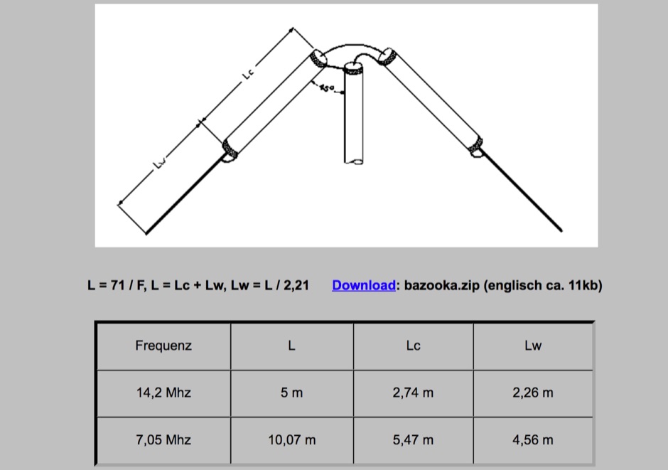 A bazooka antenna design in German with dimensions for 20m and 40m band with RG174 coax cable stronger than the common RG58
 -
 An off centre fed dipole, with 10 feet of vertical radiator. It needs no tuner on 40m, 20m and 10m by M0UKD
 -
 Operating an 80/40/20M fan dipole for DX is analyzed through EZNEC modeling, focusing on the antenna's performance in a real-world, low-height installation. The resource details the physical construction and SWR measurements of the fan dipole, comparing them against EZNEC simulations. It also incorporates High Frequency Terrain Analysis (HFTA) data to illustrate typical DX elevation angles for various regions from New England, providing a crucial context for evaluating antenna patterns. The analysis presents EZNEC-generated azimuth and elevation patterns for each band (80M, 40M, 20M) at specific frequencies, showing gain figures at different elevation angles relevant to DX propagation. It compares the modeled SWR with measured SWR, attributing discrepancies to coax attenuation. The study concludes with observations on the antenna's azimuth performance (omnidirectional within ±1.5 dB) and its less optimal elevation gain at desired DX angles, highlighting the impact of low antenna height on DX capabilities.
 -
 An homemade fan dipole antenna for 20 30 40 meter bands, setup in a 15 meter wide garden. The longest leg for 40 meter is folded to fit in the 7.5 m
 -
 Demonstrates the construction and implementation of a **two-element phased vertical array** for 40 meters, utilizing _Christman phasing_ techniques. The author, W4NFR, details the process from building individual 1/4-wave aluminum verticals to integrating them into a phased system. The resource covers antenna spacing of 32 feet, elevated radial design, and the critical steps for tuning each vertical to achieve a 1.1:1 SWR before combining them. It also provides insights into calculating precise coax lengths for feedlines and the phasing delay line, emphasizing the use of an MFJ-269 Antenna Analyzer for verification. The finished system exhibits good front-to-back nulls, with an overall SWR ranging from 1.6:1 to 2.2:1, which is managed by an antenna tuner. The project includes detailed photos of the relay box, showing 12 VDC relays capable of handling 5KV, and the control box in the shack for switching between three different antenna pattern configurations. Static bleed-off chokes are incorporated for protection, and the construction emphasizes robust weatherproofing for outdoor elements.
 -
 A simple to build full length 20/40 dipole antenna to be used in inverted vee configuration
 -
 Over 100 amateur radio beacon audio files are presented, offering a direct auditory experience of propagation conditions across a wide spectrum of frequencies, from 1.8 MHz to 47 GHz. These recordings, primarily captured by IW3FZQ and IK3NWX, document signals from beacons such as DK0WCY, IY4M, GB3RAL, and S55ZRS, providing a valuable resource for **propagation study** and **beacon monitoring**. Each entry in the list specifies the beacon's callsign, its operating frequency in kHz, and the recording operator. This compilation includes signals from beacons located in various grid squares like JN55VF, JO44VQ, and IO91IN, illustrating diverse geographical origins. The frequencies covered span the 160m, 80m, 40m, 30m, 20m, 17m, 15m, 12m, 10m, 6m, 4m, 2m, 70cm, 23cm, 6cm, 3cm, 1.2cm, and 6mm amateur bands. Users can listen to these recordings to identify characteristic beacon tones and observe signal strength variations. The resource also invites other radio amateurs to contribute their own beacon audio files, fostering a collaborative archive of propagation data. The last update to this collection was on March 24, 2009, indicating a historical snapshot of beacon activity. Accessing the files requires the Real Player software.
 -
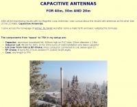
 Designing and constructing portable wire antennas for HF operations, this resource explores several configurations including the _foldback dipole_ for space-constrained setups and an inductively shortened dual-band dipole for 20m and 40m. It details the calculation of inductance for shortened elements, providing a Visual Basic 6.0 program screenshot that illustrates determining coil parameters like turns and length for a **25.5 uH** inductor. The document emphasizes practical considerations such as adjusting wire lengths for optimal SWR, noting that a dual-band dipole achieved SWR below 2:1 on both 20m and 40m, with careful adjustment bringing it under 1.5:1. Further, the resource describes a half-wave antenna matched with a coaxial stub, a method often referred to as the _Fuchskreis_ in German amateur radio circles, to transform the high feedpoint impedance to 50 Ohms. This monoband solution, for a 20m application, uses a stub length of **2.98m** (0.216 lambda multiplied by coax velocity factor) and a shorted stub of approximately 48cm. The coaxial stub design is highlighted for its resilience to ground proximity, allowing it to be rolled up or laid on the ground with minimal SWR impact, making it highly suitable for portable QRP operations.
 -
 Presents SWR analysis of an **Alpha-Delta DX-LB Plus** multiband wire antenna, installed as an inverted-V at 40 feet with ends at 15 feet, using an RigExpert AA-54 analyzer. The resource provides a full SWR sweep from 0.1 MHz to 54 MHz, followed by detailed SWR graphs for individual amateur bands including 160m, 80m, 40m, 30m, 20m, 17m, 15m, 12m, 10m, and 6m. The analysis highlights the narrow bandwidth on 80m and 160m due to loading coils, necessitating tuning for specific operating frequencies. It notes excellent SWR performance across the entire 40m band and good results on 10m, also requiring tuning. The author shares personal experience with the antenna, including a 17,000 km QSO on 20 meters, and discusses plans to replace it with a homebrewed parallel **fan-dipole**.
 -
 Amateur Radio 40m 20m 15m Half Wave Fan dipole antenna project with part list, pictures and drawing. Includes the option to expand the antenna to cover the 80 meters band
 -
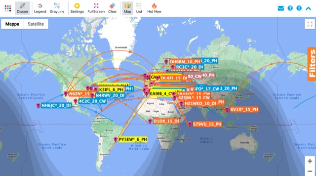 Monitoring real-time amateur radio activity is essential for DXers and contesters seeking rare contacts or tracking propagation. This online service aggregates DX spots from various **DX Cluster** networks, presenting them visually on a world map. Users can observe new spots as they appear, facilitating quick identification of active stations and potential openings. The platform offers filtering capabilities, allowing operators to narrow down displayed spots by specific bands such as 160m, 80m, 40m, 20m, 10m, and even VHF/UHF segments like 70cm and 23cm. Further refinement is possible by selecting the source continent of the spotter or the continent of the DX station, which assists in strategic operating. The service also includes a "Hot Now" list, highlighting currently active stations with recent spots. This dynamic display supports informed decision-making for pursuing **DX contacts** across different bands and geographical regions.
 -
 Covers 10m 12m 15m 17m 20m 30m 40m and 100 KHz on 80m, & WARC Eham Reviews
 -
 The dipole shown in this document is installed in an inverted Vee configuration, with two leg elements on each side held parallel to each other by 21cm spacers. The upper leg is for 40m and the lower leg for 20m. The spacers are made of 7mm plastic garden hose support for garden sprayers cut to 21cm.
 -
 The CQ World Wide DX Contest records page details the highest scores achieved in the CQ WW DX Contest across various categories and years. It systematically lists records for both SSB and CW modes, segmenting results by entry class such as Multi-Multi, Multi-Two, Multi-Single High, Multi-Single Low, Single Operator High Power, Single Operator Low Power, Single Operator QRP, Single Operator Assisted High, Single Operator Assisted Low, and Single Operator Assisted QRP. Each record entry specifies the callsign, the operator's callsign in parentheses if different, the year of operation, and the total score achieved. The data is further broken down by individual amateur radio bands, including 160m, 80m, 40m, 20m, 15m, and 10m, allowing for granular analysis of performance within specific frequency segments. The page also includes records for the "ALL" band category, representing cumulative scores across all operational bands. The presented records span from 1948 to 2025, providing a historical perspective on contest performance. This resource also references other CQ contests like CQ WPX, CQ WW RTTY, CQ WPX RTTY, CQ 160, CQ VHF, and WW DIGI, indicating a broader context of contest record keeping. It explicitly states that late logs are not included in the records, ensuring data integrity. The page is maintained by the World Wide Radio Operators Foundation, Inc.
 -
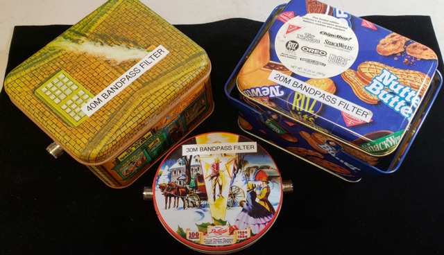 Homemade LC Bandpass Filters for 20M, 30M, 40M In multi-station environments like special events, field day, portable operating, is very important to protect receivers from excessively strong signals. Bandpass filters help to protect your transceivers.
 -
 The CQ World Wide DX Contest records document top scores, with the Multi-Multi SSB category showing CN8WW achieving **78,170,508 points** in 2000. These records span from 1948 to 2025, categorizing results by region, operating class (e.g., Single Operator High Power, Low Power, QRP, Assisted), and specific bands like 10M, 15M, 20M, 40M, 80M, and 160M. For instance, EF8R (E77DX) holds the All-Band High Power SSB record with **25,747,775 points** in 2025. Each entry includes the callsign (with operator callsign in parentheses for guest ops), year of operation, and total score. The _CQ WW DX Contest_ also features records for the RTTY and VHF contests, alongside the main SSB and CW categories. QRP records demonstrate significant achievements, such as P40W (W2GD) with 5,097,780 points in the All-Band SSB QRP category in 2000. Multi-Two and Multi-Single categories are also detailed, providing a comprehensive overview of competitive performance.
 -
 Documents the OC1I and OC6I IOTA DXpeditions to Peru, specifically highlighting operations from SA-098 (Isla La Leona) and SA-076 (Isla Lobos de Afuera). The OC1I team logged over **8000 QSOs** from SA-076, while OC6I made 1400 QSOs from SA-098, despite challenging propagation conditions. The resource details the equipment used, including an _IC-7000_, an IC-706mkIIG, and a TS-440SAT, along with various antennas such as a 160m dipole, FD4, G5RV, and a multi-band vertical for 17m, 20m, 30m, and 40m. The DXpedition dates are specified: OC6I operated from SA-098 between December 28 and December 30, while OC1I was active from SA-076 from January 2 to January 7. Both operations are confirmed as valid for IOTA credit. The page also includes a video link for the OC6I operation and a photo gallery from the DXpedition. Feedback is welcomed, and the webmaster is identified as Bodo Fritsche, DL3OCH.
 -
 Designing and constructing a two-element receiving loop antenna array for HF operation involves specific considerations for achieving high directivity and noise reduction. This resource details a homebrew system comprising two 30-inch diamond-shaped loops, spaced 20 feet apart, which are fed through mast-mounted preamplifiers and passive signal combiners. The operational principle relies on adjusting phase delays between elements via precise _Belden 8241_ coaxial cable lengths, optimized for specific bands from 160m to 20m. Performance data, derived from _EZ-NEC_ modeling, illustrates consistent 90° azimuth-plane beamwidth and low take-off angles across the target bands, with _Receiving Directivity Factor_ (RDF) values comparable to a 300-foot Beverage antenna. The article presents detailed elevation and azimuth plots for 20m, 30m, 40m, 80m, and 160m, demonstrating the array's ability to provide strong response at low DX angles while also supporting _NVIS_ signals. Key components like the _DX Engineering RPA-1_ preamplifier and _DXE RSC-2_ signal combiner are discussed, alongside the importance of impedance matching to preserve antenna patterns. The construction emphasizes self-contained elements that do not require ground radials, offering a compact solution suitable for suburban environments and stealth installations, with a focus on optimizing receive performance independently from transmit antennas.
 -
 Constructing an End-Fed Half-Wave (EFHW) antenna offers a practical solution for HF operators seeking a multiband wire antenna without the need for extensive radial systems. This design typically employs a high-impedance transformer at the feed point, matching the antenna's inherent high impedance to a 50-ohm coaxial feedline. The article specifically details a 2012 approach, focusing on a transformer with a 49:1 turns ratio, which is a common configuration for EFHW antennas. The resource outlines the construction of a wire element cut for a half-wavelength on the lowest desired band, with specific coil arrangements enabling operation on harmonically related bands such as 40m, 20m, and 10m. It discusses the physical dimensions and winding details for the matching transformer, often utilizing a ferrite toroid core to achieve the necessary impedance transformation. The content provides insights into the operational principles and practical considerations for deploying such an antenna, including methods for tuning and optimizing performance across multiple amateur radio bands. While acknowledging that the presented information from 2012 may be superseded by newer insights, it serves as a foundational reference for understanding EFHW antenna theory and construction.
 -
 Author experiments end fed half wave antennas using common two conductore speaker wire, this article features a couple of end-fed halfwave wires for the 40M and 20M bands.
 -
 Presents various amateur radio topics through blog posts, detailing operational experiences and technical insights from the perspective of SV2YC. The content frequently discusses antenna projects, such as a **portable 20m/40m dipole** designed for rapid deployment, and explores the performance characteristics of different wire configurations in varied field conditions. Observations on propagation and band activity across the HF spectrum are also regularly documented, providing practical context for fellow operators. Specific entries often include detailed accounts of **DX contacts** and participation in minor contests, outlining station setup, power levels, and antenna choices. The blog also covers modifications to commercial transceivers and homebrew accessory construction, offering practical advice on improving station efficiency and functionality. Further posts delve into software applications for logging and digital modes, sharing configurations and operational tips for maximizing their utility in daily amateur radio activities.
 -
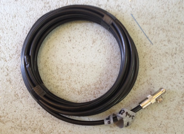 When operating contest in a multi transceiver environment interferences between the 40m and 20m are guaranteed. An easy and inexpensive way to reduce interferences is to add coax stub filters
 -
 Constructing a dual-band antenna for 40 and 20 meters often involves compromises in size or complexity. This resource presents a compact _open sleeve dipole_ design that addresses these challenges by using 450-ohm ladder line and folded elements to achieve a total length of approximately **17.17 meters**, significantly shorter than a full-size 40-meter dipole. The design leverages electromagnetic coupling, where a primary radiator handles the 40-meter band, and a second conductor resonates on 20 meters without direct electrical connection. This configuration eliminates the need for traditional traps, loading coils, or switching components, simplifying construction and reducing potential loss points. The antenna is fed with RG-58C/U coaxial cable, and a common-mode choke is recommended at the feed point to suppress sheath currents, ensuring a cleaner radiation pattern and minimizing RF in the shack. The design is well-suited for portable operations, field deployments, temporary installations, and restricted urban environments where space is a premium, offering solid performance on both HF bands.
 -
 A mircovert antenna assembled for the 40m version of the DL7PE antenna. A one meter long aluminum tube with 24mm diameter is used for the base (element 1) and a 50cm aluminum tube with 20mm diameter for element 2 (the extention). A pvc pipe, 34cm long and with a diameter of 38mm, is used to wind the coil on (1mm enamelled copper wire).
 -
 Operating as FY/F5UII, Christian F5UII conducted a DXpedition to French Guiana (FY) from January 13 to 30, 2013. The primary operation utilized the FY5KE radio club station in Kourou, with activity focused on voice modes during specific weekday hours. The resource details the operator's intent to transmit before 12:00z and after 22:00z, or as availability permitted, from the mainland. A significant aspect of this operation involved a dedicated weekend activation of the Salut Islands, specifically **IOTA SA-020**, from January 19-20, 2013. This segment of the DXpedition was conducted from Royal Island (Ile Royale), part of a group including Devil's Island (Ile du Diable) and St. Joseph Island (Ile Saint Joseph), located 14 km offshore from Kourou. The station setup for the IOTA activation included 100 Watts of power, a GPA-030 vertical antenna for 10m, 15m, and 20m, and dipole antennas for 17m and 40m, with antenna deployment contingent on site conditions and propagation. The operator anticipated strong interest for the SA-020 entity.
 -
 Listen to online WebSDR located in Andorra Europe. Four receivers on 60m, 20m, 40m, and 80m, connected to a dipole antenna direction East/West