Search results
Query: all band wire antenna
Links: 128 | Categories: 1
Categories
-
 The W5GI Mystery Antenna is a versatile multi-band wire antenna designed for amateur radio operators. It covers frequencies from 80 meters to 6 meters, making it suitable for a wide range of operating conditions. The antenna features a low feed point impedance, allowing for easy matching with most radios, whether or not an antenna tuner is used. Its construction is straightforward, requiring only two vertical supports approximately 130 feet apart, making it ideal for hams without towers. Users have reported excellent performance, particularly on the 20-meter band, where it outperforms similar designs like the G5RV. This antenna is unique in its design, incorporating three half waves in-phase on 20 meters, resulting in a six-lobe radiation pattern. Despite its effective performance, the antenna is challenging to model, which adds to its mystique. The W5GI Mystery Antenna has gained popularity among amateur radio enthusiasts worldwide, with many users praising its ease of construction and effectiveness. Whether you're a beginner or an experienced operator, this antenna offers a fun and rewarding project that can enhance your HF capabilities.
 -
 Demonstrates the construction of a **multi-band HF mobile antenna** utilizing a modified CB whip antenna base. The resource details the process of stripping a commercial CB whip, winding a new helical coil with 0.7mm insulated copper wire, and identifying tapping points for various HF bands. It emphasizes the importance of a rugged, slim design for mobile operation, discussing mechanical length, power handling (up to 200 watts), and coil diameter considerations. The article includes a graphic illustrating the antenna's operational principle, where sections of the helical coil are shorted from bottom to top to maintain efficiency and high Q. The resource presents a practical approach to achieving **band switching** without an external tuner, by manually adjusting tapping points on the coil. It provides a table with reference lengths in centimeters from the feedpoint for 7 MHz (40m) through 28.7 MHz (10m), including WARC bands. The author details mounting techniques, suggesting a Diamond bracket for secure attachment to a vehicle trunk, and stresses the critical role of proper grounding for optimal performance. The design allows for operation on 75m and 80m bands by adding a 110mm steel whip.
 -
-
 A 10-20 meters coverage delta loop antenna. After relocating, DL2HCB designed a multiband loop antenna to cover 10-20m with an open-wire feed for impedance matching and compact installation. Inspired by the mini-X-Q design, a modified 10m delta-loop was built, enhanced with a 1/4 wave shorted stub for 28 MHz using 450-ohm ladder line. The antenna delivers east-west broadside radiation and performs as a closed loop on other bands. Operational tests yielded strong European signals and successful DX contacts, including a 20m QRP QSO with FY/DJ0PJ.
 -
 The G5RV antenna, with an overall length of **31.10m (102ft)**, functions as a 3/2-wave on 20 meters when installed horizontally at 12m (39ft), exhibiting a resonant frequency of 14.150MHz and an approximate resistance of 80 ohms. Its 10.36m (34ft) stub line, designed as a 1/2-wave on 14.150MHz with a 0.97 velocity coefficient, acts as an impedance transformer across other bands, aiming for multiband operation without traps. On 20m and higher frequencies, the G5RV demonstrates improved gain compared to a standard dipole, attributed to the _collinear effect_ from multiple 1/2-waves along the wire. The original design sought a multiband solution for limited spaces, often requiring an Antenna Tuning Unit (ATU) for effective operation across bands like 80, 40, 30, and 20m, particularly with modern solid-state PAs. Variants, such as the F8CI modification, incorporate a 1/4 current balun at the stub line's base for symmetrical-to-asymmetrical transition, known as a _remote balun_. Proper flat-top or inverted-V installation is critical for maintaining symmetry and collinear gain, with inverted-V apex angles below 120° progressively diminishing higher-band performance.
 -
 The page provides detailed information on the G5RV antenna, its feeder arrangement, and efficient operation on HF bands from 3.5 to 28 MHz. It includes dimensions for installation in limited spaces, variations for different bands, and impedance matching details.
 -
 Details the construction of a **multiband vertical** antenna, specifically designed for stealth operation in a rented property, covering 80m, 60m, 40m, and 30m. The author, N3OX, leverages a 12m Spiderbeam telescoping fiberglass pole as the primary support, noting its sturdiness compared to typical fishing rods while remaining light enough for quick deployment and takedown. The radiating element is a 14 gauge Flex-Weave wire, attached to the pole's top with a rubber grommet, and fed by 27 bare 18 gauge radials spread across a 40-foot square backyard. N3OX describes the impedance matching solution, opting for custom-built L-networks over a remote tuner to enable fast bandswitching. Using an MFJ-259B and EZNEC modeling, base impedances were measured and component values calculated with G4FGQ's L_TUNER and SOLNOID_3 programs. The 80m coil is wound on a 3.5-inch PVC form, while the 30m, 40m, and 60m coils are air-wound, self-supporting #10 wire. Variable capacitors are incorporated for 40m and 30m shunt elements, with the 60m impedance matched by a series inductor. The project includes a **servo-controlled** homebrew band switch, utilizing a two-pole 12-position ceramic wafer switch for remote operation, addressing the limited 80m bandwidth. The entire matching network is housed in a weather-resistant shelter constructed from lumber and aluminum flashing. N3OX reports good DX results at 100W, estimating the total cost between $150 and $250, depending on existing parts.
 -
 Low noise, receive only coax loop antennas for 160 - 10 meters HF bands
 -
 High Performance Lightweight Antennas. The spider beam is a full size lightweight tribander yagi for 20/15/10m, made from fiberglass and wire. It has been specially developed as a highly efficient antenna for dx-pedition and portable use.
 -
 Build your mobile antenna which outperforms Hustler by 10db and ATAS-100 by 18db. From 80 to 10m. The HB9ABX mobile HF antenna, designed for 10 to 80 meters, was developed by Felix Meyer and outperforms commercial antennas like HUSTLER and YAESU ATAS-100/120 in field tests. Made from fiberglass rods and enamelled copper wire, it includes a loading coil with adjustable taps for tuning across bands. Installation requires solid grounding, and adjustments are made via whip length and coil settings. An antenna tuner ensures optimal SWR. Users must handle fiberglass with care due to health risks. This design proved highly effective in South America and Europe.
 -
 Details the construction of a J-vertical antenna specifically for the 10-meter band, offering a practical alternative to a _Slim Jim_ design for 28 MHz. The resource outlines the use of aluminum tubing for the half-wave vertical section and coaxial cable for the quarter-wave matching section, providing specific calculations for element lengths based on frequency and coaxial cable velocity factor. It contrasts the performance of the J-vertical with center-fed dipoles and end-fed verticals, noting superior results in previous comparisons. The article further presents a more recent iteration of the J-vertical, constructed using a fiberglass pole and insulated wire, with updated dimensions for 28.8 MHz. It includes practical advice on weatherproofing connections and securing the antenna for durability against adverse conditions, referencing the survival of an original _J Vertical_ during 110 MPH winds in 1987. The SWR performance is reported as 1.1:1 at 28.6 MHz, maintaining below 1.5:1 across 28.3 to 29 MHz.
 -
 The boomless quad antenna is a unique design that offers versatility for amateur radio operators. This antenna consists of two half-wave dipoles arranged in a square or circular shape, allowing for both vertical and horizontal polarization depending on the feed point. The design facilitates easy installation and rotation, making it suitable for various operating conditions. The construction utilizes strong materials, such as bamboo, and incorporates waterproofing techniques to enhance durability. This project outlines the necessary dimensions and materials, including copper wire and insulators, to successfully build the antenna. It emphasizes the importance of tuning each radiator element for optimal performance. The boomless quad is particularly effective across multiple HF bands, including 14 MHz, 21 MHz, and 28 MHz. By following the detailed instructions, operators can achieve a reliable and efficient antenna setup that enhances their DXing and contesting capabilities.
 -
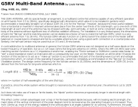
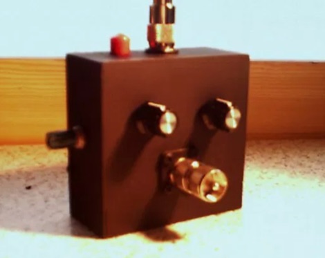
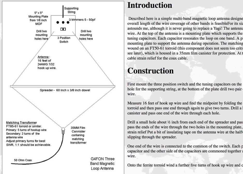 Described here is a simple multi-band magnetic loop antenna designed for 20, 30 and 40 metres, but by changing the overall length of the wire coverage of other bands is feasible
 -
 M1IOS Wonder Whip antenna - The M1IOS Wonder Whip A 10 dollars QRP Portable Multiband Antenna for HF, VHF and UHF A variation on the Miracle Whip and Wander Wand. This antenna tuning unit will get your SWR really low on telescopic whips, mobile 3/8th antenna and long wires. A remarkable little tuner that really works!
 -
 Presents the KE4UYP linear-loaded vertical antenna design, which introduces very little loss on 80 or 160 meters, achieving an overall radiation efficiency of 80% to 85%. This design addresses common pitfalls of traditional base-fed verticals by placing the majority of the current at the top of the antenna, eliminating the heavy reliance on extensive ground radial systems. The author's initial 10-meter model, only three feet tall, yielded 5/9 signal reports to Anchorage, AK, and Europe, confirming its effectiveness. The antenna incorporates both vertically and horizontally polarized radiators, with a 1/4 wavelength horizontal counterpoise located at the feed-point, near the top, to create an almost totally omnidirectional pattern with high wave angle horizontally polarized radiation. This dual polarization ensures even illumination across all take-off angles, making it effective for both local contacts and **DXing**. The vertical element is linear loaded, adding capacitance reactance and making it longer than the horizontal element to achieve resonance and raise the feed-point impedance to 50 ohms. Fine-tuning the antenna requires careful adjustment, as tower reactance can vary. The article suggests starting with 80 feet for 80m and 170 feet for 160m for the vertical wire, then trimming for resonance. Bandwidth specifications include 300 kHz under 2:1 **SWR** on 80m and 100 kHz on 160m when suspended between trees, or 150 kHz on 80m when side-mounted on a tower.
 -
 The Flower Pot Antenna project details a portable dual-band antenna primarily operating on 10 meters, with secondary resonance near the 30-meter band. Construction involves winding RG58 coaxial cable uniformly around a large plastic flower pot, approximately 70cm high with a 60cm top diameter. The design eliminates the need for radials, contributing to its compact and lightweight nature. Key construction steps include soldering the inner conductor to the shield at one end of the wound cable and connecting the wound cable's shield to the rig cable's inner conductor at the base. An LC network, comprising a variable capacitor (0-200pF) and an inductor (10 coils, 5cm diameter, 2mm wire), is inserted between the wound cable's inner conductor and the rig cable's shield. Tuning is performed with an antenna analyzer, adjusting cable length and the variable capacitor for optimal impedance on 10 meters. The antenna performs effectively when installed horizontally.
 -
 The 80-meter loop antenna, measuring 86 meters (282 feet) of wire, effectively operates across 8 HF bands from 80 through 10 meters, despite its length being a compromise for specific bands. This design prioritizes a "low enough" SWR across multiple bands, aiming for lower SWR values on higher frequencies due to increased feedline losses. A 200-ohm feedpoint impedance provides a workable SWR on every band, with feedpoint impedances ranging from 100 ohms for lower bands to 300 ohms for higher bands. Radiation patterns for the 80-meter loop, mounted at 15 meters high, show a maximum gain of 7.6 dBi at a 90-degree takeoff angle on 80 meters, and up to 12.9 dBi at a 10-degree takeoff angle on 12 meters. This configuration supports regional contacts on 80 meters and provides good DX performance on higher bands. Practical construction notes emphasize using robust supports like trees, ensuring wire slack with _egg insulators_ for wind resilience, and employing an oversized 2 kW 4:1 _balun_ to safely handle higher SWR conditions, even with 100W transceivers. Feedline losses are minimized using _LMR-400_ coax or ladder line, with power transfer efficiency between 80% and 95%. Antenna simulations were performed using _xnec2c_, and the provided NEC file is compatible with other NEC2 derivatives. The antenna is tunable on 6 of 8 bands with an internal ATU and all 8 bands with an external autotuner like the LDG AT-200 Pro.
 -
 The Bruce array is a simple, often-forgotten wire antenna array that is advantageous for 80 and 160 meters, where typical gain antennas are very large. This bi-directional broadside vertical array is only 1\4 lambda high and does not require a ground system. It offers substantially greater SWR bandwidth than the half-square or bobtail curtain. A 4-element Bruce array used by N6LF showed a gain of about 4.6 dB compared to a 1\4 lambda vertical with 8 elevated radials, with a 2:1 SWR bandwidth greater than 400 kHz. The antenna is simple and its dimensions are flexible.
 -
 This project details three variants of a vertical half-wave antenna design for the 4-meter (70MHz) amateur radio band. The antennas use end-feeding with a parallel-tuned circuit for impedance matching to 50-ohm coaxial cable. The first variant uses suspended flexible wire for portable use, the second employs a fiberglass rod with internal wire for permanent outdoor installation, and the third utilizes aluminum tent poles for quick mobile deployment. Despite the narrow bandwidth of the matching circuit, this suits the narrow 4m FM allocation well. The design offers an effective omnidirectional radiation pattern and can be constructed with readily available materials.
 -
 This multiband wire antenna it is an off centre fed dipole, with 10 feet of vertical radiator, needs no tuner on 40m, 20m and 10m and works fine on all bands above 40m with a tuner, and even below 40m on 60m, and 80m.
 -
 Demonstrates the construction and performance of an updated ZS6BKW multiband dipole, a variant of the _G5RV_ antenna, specifically designed for HF operation. The article details a real-world installation using 13.5m copper wire elements and 12.2m of 450 Ohm ladder line, configured as a sloping inverted-V with the apex at 10m and ends at 4m above ground. It covers the critical aspect of impedance matching, incorporating an 8-turn choke balun at the feedline transition to RG-58U coax to mitigate RF common mode current. Measurements confirm favorable SWR readings below **1.3:1** on 7.1 MHz, 14.11 MHz, 18.06 MHz, and 24.8 MHz, indicating effective resonance across 40m, 20m, 17m, and 12m bands. The installation also shows usable SWR dips on 3.55 MHz (5:1), 29.02 MHz (2:1), and 50.84 MHz (3:1), extending its utility to 80m, 10m, and 6m with an antenna tuning unit. Initial on-air results report clear reception of stations over **5000km** away, validating its DX potential.
 -
 The Windom is an Off-center wire multiband Antenna. The old version was fed just by a single-wire connected on 1/3 of antenna's overall length or with an open-line feeder (later versions). Here is another model with coaxial feeder, which is compatible with Solid States - 50 Ohm output transceivers .
 -
 A multiband stealth antenna. Tuner is required. The antenna is made from a $15, 500 ft roll of black #14 insulated stranded wire, about 120 small black wire ties, and maybe 30 or so large black wire ties.
 -
 This article describes the construction of a Moxon rectangle antenna for the 70MHz (4-meter) amateur radio band. This compact two-element beam design features folded element ends, reducing its width to approximately 75% of a half-wavelength. The antenna was built using enamelled copper wire stretched over a lightweight fiberglass kite spar frame, with a direct coaxial cable feed connection. Initial testing showed a VSWR of around 1.3 with distinct nulls at 90 degrees when horizontally mounted. The author later tested vertical polarization and suggested that the antenna's compact size might allow for indoor loft installation.
 -
 This Multiband Cubical Quad antenna a boomless Quad design with glass-fibre arms and a single coax wire connected to a remote antenna switch. This aerial work on 8 bands and has a 60-degree beam width. Despite achieving critical technical requirements, the antenna's three-dimensional structure presents obstacles, such as installation issues on fixed towers and risk of frost damage. The spider framework is built of stainless steel, with a compact 18-inch boom and strong angle iron arms. Tait use a variety of methods to fasten element wires and suggests placing them on the outside of the spreaders for improved insulation. The use of nylon twine or parachute cord between key attachment points allows for adjustable separation between pieces.
 -
 The ZS6BKW multiband HF antenna, a design by ZS6BKW (G0GSF), functions effectively on multiple HF bands without requiring an Antenna Tuning Unit (ATU) for 40, 20, 17, 12, 10, and 6 meters. This antenna, approximately **27.51 meters** (90 feet) long with a 12.2-meter (40-foot) open-wire feeder, is a direct descendant of the _G5RV_ but offers superior multi-band resonance. It can be deployed as a horizontal dipole or an inverted-vee, with the latter requiring only a single support and maintaining an apex angle of at least 90 degrees to prevent signal cancellation. Performance data, recorded with an MFJ Antenna Analyser, indicates SWR values of 1:1 on 7.00 MHz (40m) and 14.06 MHz (20m), with SWR below 1.3:1 on 17m, 10m, and 6m. While primarily designed for these bands, the antenna can be adapted for 80m, 30m, and 15m with an ATU, preferably at the balanced feeder's base. The use of 450-ohm twin-lead for the feeder is recommended over 300-ohm for improved strength and reduced losses, especially in adverse weather conditions. This design, originally published in _RadCom_ in 1993 and featured in Pat Hawker’s "Antenna Topics," provides a compact and efficient solution for HF operation, particularly for those with limited space or resources.
 -
 A **90-foot tall** top-loaded vertical antenna for the 160-meter band is detailed, constructed from aluminum irrigation tubing. The design incorporates four sets of four guy wires for structural stability, essential for an antenna of this physical size. This _monoband_ vertical is optimized for low-band operation, providing a robust solution for DXing and contesting on 1.8 MHz. The document includes specific construction methods for assembling the aluminum irrigation tubing sections and securing the guy wires. While a full NEC model is not explicitly provided, the physical dimensions and construction materials are sufficient for replication by experienced builders. The antenna's height and top-loading configuration are critical for achieving efficient radiation on 160 meters, particularly in minimizing ground losses.
 -
 F6EZX presents a detailed account of constructing a compact, multi-band _Levy antenna_ for portable holiday operations, specifically addressing issues with local QRM from a previous _Deltaloop_ setup. The article outlines the design criteria, including multi-band operation on 40m, 30m, 17m, 15m, 12m, and 10m, a symmetrical configuration to reduce interference, and a low take-off angle for DX. Construction involves 2x 10.3m radiating elements and a 15.3m open-wire feeder (ladder line) with 7cm spacing, made from 1.5mm2 copper wire and foam pipe insulation spacers. Theoretical calculations, referencing F9HJ's "_Les antennes Levy_" book, guide the determination of element lengths and feeder impedance characteristics, aiming for a good match across bands with a commercial antenna tuner. Initial field tests with the _VCI Vectronics VC300DLP_ tuner showed a 1:1 SWR from 80m to 10m, with some difficulty on 17m. The antenna, mounted as a 45-degree slopper with the high point at 12m, successfully facilitated DX contacts to South America, particularly Chile and Argentina, suggesting a lower take-off angle compared to the previous Deltaloop which favored Brazil. The Levy antenna significantly reduced TVI/RFI, attributed to its improved symmetry and greater distance from the QRA. While signal reports on 15m and 20m were 1-2 S-points lower than the Deltaloop, its performance on 40m and 30m was comparable, fulfilling the design goals for a portable, low-cost, multi-band solution.
 -
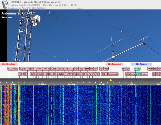 OE4RLC, OE3DUS in Allhau Austria with wire antenna and full HF amateur radio bands coverage
 -
 End-Fed Half-Wave Antennas (EFHWAs) are analyzed for their utility in portable QRP operations, emphasizing their simplicity, efficiency, and predictable radiation patterns compared to other portable antenna types. The discussion contrasts EFHWAs with vertical antennas, random length wires, and center-fed dipoles, highlighting the common pitfalls of each, such as ground system dependency for verticals and feedline issues for dipoles. The article details the electrical half-wavelength calculation using the formula L (Ft) = 468/F(MHz) and explains how EFHWAs can be resonant on harmonic frequencies, enabling multiband operation. Various deployment configurations are presented, including the inverted L, inverted Vee, sloping wire, and vertical setups, each with specific advantages for radiation angle and polarization. For instance, a vertical EFHWA offers a low angle of radiation suitable for DX contacts without requiring an extensive ground system. The resource also addresses the counterpoise requirements, suggesting a quarter-wavelength wire or connection to a metallic structure for decoupling. A schematic diagram for a simple parallel-tuned circuit tuner, based on the _Rainbow Bridge/Tuner_ design, is provided, detailing component values for 30 and 40 meters, including a 6 microhenry toroidal inductor and a 20-100 picofarad mica compression capacitor. The tuner's adjustment process for SWR matching is also outlined.
 -
 This PDF document, authored by KT4QW in October 2004, details the construction and modeling of a dual-band, horizontally polarized hanging rectangular loop antenna for **10 and 17 meters**. The design, adapted from *The ARRL Handbook*, utilizes _NEC4WIN95_ software for scaling and optimization, targeting a 50 ohm feedpoint impedance. The resource includes a bill of materials, step-by-step construction instructions, and a discussion of the antenna's radiation characteristics. It presents NEC-generated elevation and azimuth patterns, comparing the loop's performance to a half-wave horizontal dipole at the same height and frequency. The 17-meter element is centered at 18.140 MHz for low SWR across the phone band, while the 10-meter element is centered at 28.500 MHz. Construction involves 14-gauge stranded copper wire and Schedule 40 PVC spreaders, with the total wire length calculated by the formula: Length in feet = 1005/MHz. The feedpoint impedance can be adjusted by modifying the rectangular aspect ratio. The document specifies hoisting the antenna to at least a half-wave above ground for testing. It notes that a balun was tested and found to have no measurable effect on SWR or radiation characteristics. A 2-meter scale model is presented to illustrate the physical design, and a "rotator" string is incorporated for directional adjustment up to 90 degrees.
 -
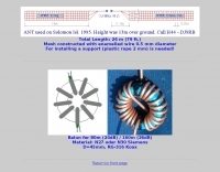 Mesh constructed with enamelled wire 0.5 mm diameter For installing a support (plastic rope 2 mm) is needed. Antenna used on Solomon Isl in 1995 H44/DJ9RB
 -
 Simple, inexpensive and easy to erect, this antenna provides directivity, low angle radiation and a small gain on a number of HF bands.
 -
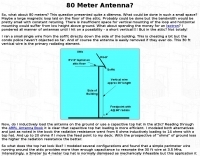 This article describe a small single wire antenna running on the side of the building allow operations on 80 meters band
 -
 Antenna Warehouse provides a range of certified quality wire products for amateur radio and general communication applications. Their inventory includes Francis antennas, known for their robust construction, alongside the versatile Select-A-Tenna series. The company also stocks Solarcon 10/11 meter base antennas, catering to specific band requirements for 27-28 MHz operations, and various Wilson antenna models. Beyond product sales, Antenna Warehouse offers services such as antenna tower installation, repair, and removal. These services support the complete lifecycle of antenna systems, from initial setup to maintenance and decommissioning. The product selection emphasizes components for both fixed station and mobile installations.
 -
 If you are looking for an easy antenna for your favorite band, you can't go wrong with an halfwavelenght dipole, all you need is 3 insulators and some wire
 -
 Described is a simple inverted-V antenna which, when used with a balanced ATU, can be used on all the main Radio Amateur HF bands (80, 40, 20, 15 and 10m). The cental support is made in such a way that the wire can be coiled up for storage when the antenna is taken down.
 -
 The document details the optimization and construction of the _Maria Maluca_ antenna, a compact 6-band (20m-6m) directional beam. It presents a comparative analysis of shortwave antenna principles, highlighting the efficiency gains achieved by using an open feeder line and tuner as a resonant unit, contrasting this with the losses associated with traps or capacitive loads in multiband antennas. The resource specifically revisits an older South American 2-element design for 10, 15, and 20 meters, applying modern NEC-based software to develop a six-band version. Performance data is meticulously tabulated, showing impedance, free space gain, gain at 12m height, elevation angle, and front-to-back (F/B) ratio for each band from 20m through 6m. For instance, on 15m, the antenna achieves 5.1 dBd free space gain and 13.72 dB F/B ratio. The construction section provides practical guidance on element assembly using aluminum pipes and hose clamps, detailing the use of a heavy-duty glass fiber reinforced polyamide rod for electrical separation and bending strength. It also specifies the use of 450-ohm _Wireman_ line CQ 552 for the transmission line. The document includes diagrams for rod fixing, an air-wound balun, and a vertical elevation diagram for the 15m band, illustrating its DX qualification. It also discusses the antenna's suitability for portable and expedition operations, noting its compact transport dimensions (max 1.50m length, 12 lb weight) and quick assembly time (under 15 minutes). The author, Dipl.Ing. Helmut Oeller, DC6NY, is identified as a source for material kits.
 -
 The G5RV antenna, a popular multi-band wire antenna, typically employs a center-fed design with a specific length of 300-ohm or 450-ohm open-wire line acting as an impedance transformer, feeding a coaxial cable run to the shack. Its overall length for 80-10 meters is approximately 102 feet (31 meters) for the flat-top section, with a 34-foot (10.36 meter) matching section. The original design by Louis Varney, G5RV, aimed for efficient operation on 14 MHz (20 meters) as a 3-half-wave antenna, with the matching section providing a good match to 50-ohm coax on that band. While the G5RV offers multi-band capability, its performance varies across bands, often requiring an antenna tuner for optimal SWR on bands other than 20 meters. The matching section's length is critical for its impedance transformation properties, influencing the feedpoint impedance presented to the coaxial cable. Variations like the G5RV Junior and ZS6BKW utilize different flat-top and matching section lengths to optimize performance for specific band sets or to achieve a lower SWR without a tuner on certain bands, demonstrating the adaptability of the basic G5RV concept.
 -
 Presents the design and construction of the OK2FJ Bigatas, a portable, automatically tuned vertical antenna covering 80 through 10 meters. It details two distinct control systems: one utilizing BCD band data from Yaesu FT-857/897 transceivers, and another employing voltage level sensing for the Yaesu FT-817. The resource provides specific instructions for building the antenna's radiating element, loading coil with switchable taps, and the control circuitry, emphasizing the use of readily available components. The article outlines the physical construction of the antenna, including the use of duralumin tubes for the radiator and a PVC tube for the coil form. It specifies coil winding details, tap points, and the integration of radial wires for ground plane operation. The control electronics section provides schematics and component lists for both the BCD decoder (using a 74LS42 IC) and the voltage comparator (using an _LM3914_ bargraph driver), enabling rapid, automatic band switching without the minute-long tuning delays common in other systems. Crucially, the antenna achieves rapid band changes, with typical SWR values centered on common operating segments, such as **3.7 MHz** for 80m SSB. It also discusses modifications for CW operation on 80m and the trade-offs between antenna efficiency and full-range automatic tuning on higher HF bands, where manual adjustment of radiator length is suggested for optimal performance on 15m, 12m, and 10m. The resource includes construction photos and a discussion of cable requirements for reliable operation.
 -
 JJ0DRC's HF multi-band delta loop antenna project, initially conceived during the waning peak of Cycle 23, addresses the common challenge of achieving effective DX operation from a small residential lot in Japan. Dissatisfied with a ground plane antenna's performance in SSB pile-ups, the author sought a beam-like solution without a tower, drawing inspiration from a JJ1VKL article in CQ Ham Radio Sep. 2000. The antenna, constructed in October 2000, employs two 7.2-meter fishing rods (37% carbon fiber, reinforced with cyano-acrylate glue and aluminum tape) and 1mm enameled wire, fed by an Icom AH-4 external antenna tuner. While the exact beam pattern remains unmeasured, JJ0DRC observed a significantly higher callback rate compared to dipole antennas, particularly on higher bands. The system's circumference length of 15-20m is crucial for maintaining a good beam pattern across HF bands, though performance on lower bands like 80m, 40m, and 30m becomes less directional as the length deviates from a full wavelength. Ongoing maintenance addressed degradation issues, including aluminum tape cracking and wire breakage at connection points due to strong winds (often exceeding 10-15m/s in winter). The author reinforced rod connections with IRECTOR PIPE SYSTEM components and INSU-ROCK ties, and improved wire attachment methods using Cremona rope and epoxy bond to enhance durability.
 -
 This resource details the computer-optimized design of the _ZS6BKW_ multiband dipole, an evolution of the classic _G5RV_ antenna. It begins by referencing the original 1958 RSGB Bulletin article by Louis Varney G5RV, explaining the operational principles of the G5RV's flat-top and open-wire feedline on 20m and 40m, noting its impedance transformation characteristics for valve amplifiers of that era. The article then transitions to the rationale for optimizing the design for contemporary solid-state transceivers requiring a 50 Ohm match. The core of the project involves using computer modeling to determine optimal lengths for the flat-top and matching section, aiming for a VSWR of less than 2:1 on multiple HF bands. It discusses the process of calculating feedpoint impedance based on antenna length and frequency, referencing professional literature from Professor R.W.P. King at Harvard University. The analysis also considers the characteristic impedance (Z(O)) of the open-wire line, identifying a broad peak of adequate values between 275 and 400 Ohms. Specific design parameters for the improved ZS6BKW are presented, including a shorter flat-top and a longer matching section compared to the original G5RV, with a velocity factor of 0.85 for the 300 Ohm tape. The article confirms acceptable matches on 7, 14, 18, 24, and 28 MHz bands when erected horizontally at 13m, and also discusses performance in an inverted-V configuration, noting frequency shifts. The author, Brian Austin ZS6BKW, emphasizes the antenna's suitability for modern 50 Ohm coaxial cable without a balun.
 -
 A quarter wave vertical end-fed antenna for the 40 meters band. As all vertical antennas, also this aerial requires a good earthing system. In this project the ground is composed by twelve 4, wires buried in the lawn by using a spade to create a slit to drop the wire into.
 -
 Presents a comprehensive guide for constructing a broadband Hex Beam antenna, a popular directional array for HF operation. This design offers a compact footprint and excellent gain characteristics, making it suitable for limited space installations while providing significant performance advantages over omnidirectional antennas. The resource details the specific dimensions for a five-band Hex Beam covering 20, 17, 15, 12, 10, and 6 meters, emphasizing the critical element spacing and wire lengths required for proper resonance and pattern. It outlines the construction of the center post, spreaders, and wire elements, along with the feed point assembly, ensuring proper impedance matching. The project aims for a forward gain of approximately **5.5 dBi** on most bands, with a front-to-back ratio often exceeding _20 dB_. Building this antenna requires careful measurement and assembly, but the resulting performance provides a substantial upgrade for DXing and contesting.
 -
 Hexagonal wire beams for all hf bands, technical resource, EZNEC files, tools for antenna modeling and documentation. You can also order parts to build your own antenna.
 -
 This project outlines the construction of a 3-element reversible quad antenna specifically designed for the 40-meter band. The materials required include pushup towers, pressure-treated posts, insulated wire, and various electrical components such as relays and a balun. The construction process is straightforward, beginning with the installation of the posts in a straight line, followed by the assembly of the antenna elements and their elevation to the desired height. The antenna's design allows for directional signal reception, making it ideal for operators looking to enhance their communication capabilities on the 40-meter band. The project includes detailed instructions on tuning the antenna for optimal performance, ensuring that operators can achieve the lowest SWR possible. Additionally, the design can be adapted for other bands by extrapolating dimensions, providing versatility for amateur radio enthusiasts. Overall, this reversible quad antenna project is suitable for both beginners and experienced operators, offering a practical solution for improving signal strength and directionality in 40-meter communications.
 -
 Put up the longest dipole you can fit, feed it with open wire line, connect it to the balanced output of your tuner and poof! Instant multiband antenna. Is life really that simple?
 -
 D3+ High Performance Antennas for Field Day. This article describes versatile broadband wire antennas. These antennas will double your effective radiated power over a dipole, will be easy and inexpensive to build and install, and will be simple to match.
 -
 The ZS6BKW wire antenna, a variant of the G5RV, utilizes a specific 13m (42.6 ft) length of 450-ohm window line as its matching section, feeding a 28.5m (93.5 ft) flat-top element. This design aims for lower SWR on 40m, 20m, 17m, 12m, and 10m compared to a standard G5RV, often achieving SWR values below 1.5:1 on these bands without an antenna tuner. The feedpoint impedance transformation provided by the window line allows for direct connection to 50-ohm coax on multiple bands. F4FHH's experience involved constructing the ZS6BKW and evaluating its performance against an _OCF dipole_ (Off-Center Fed) on various HF frequencies. The article includes observations on SWR readings and operational effectiveness, highlighting the ZS6BKW's suitability for multi-band operation. The antenna's overall length, including the flat-top and window line, is approximately **41.5 meters** (136 feet), making it a significant wire antenna for fixed station use. Comparative analysis with the OCF dipole provided practical insights into the ZS6BKW's advantages and limitations, particularly concerning bandwidth and tuner requirements.
 -
 The Classic Multiband Dipole Antenna QST article. The open-wire feed line dipole antenna is easy to install and offers surprising performance on several bands. You can install it in almost any configuration; it does not have to be strung in the traditional horizontal flat top