Search results
Query: antenna review
Links: 238 | Categories: 20
Categories
- Radio Equipment > Antenna Tuners
- Radio Equipment > HF Vertical Antenna
- Radio Equipment > HF YAGI Antennas
- Radio Equipment > Reviews and Comparisons
- Radio Equipment > HF Portable Antenna > Super Antennas MP-1
- Radio Equipment > HF Portable Antenna > TransWorld Antennas TW2010
- Radio Equipment > Antenna Analyzers > Array Solutions AIM 4170D
- Radio Equipment > Antenna Tuners > AT-Auto
- Radio Equipment > HF Portable Antenna > Buddipole
- Radio Equipment > HF YAGI Antennas > Cushcraft MA5B
- Radio Equipment > HF Vertical Antenna > Cushcraft R5
- Radio Equipment > HF Vertical Antenna > Cushcraft R7
- Radio Equipment > HF Vertical Antenna > Cushcraft R8
- Radio Equipment > HF YAGI Antennas > Cushcraft X7
- Radio Equipment > HF Vertical Antenna > Hustler 5-BTV
- Radio Equipment > HF Vertical Antenna > Maldol MFB-300
- Radio Equipment > Antenna Analyzers > MFJ-259B
- Radio Equipment > Antenna Tuners > MFJ-989C
- Radio Equipment > HF Vertical Antenna > Solarcon A-99
- Shortwave Radio > SWL Resources
-
 PDF file by QRP Expressions by By N. T. Len Carlson, K4IWL
 -
 Simple vertical radiator with matching box. No traps, no tuner required for this multiband antenna
 -
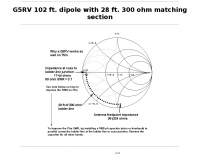
 G5RV 40m Beam Antenna. Adding a 28 ft. piece of vertical wire to one end of a 102 ft. center-fed dipole turns it into a 40m beam with a very wide beamwidth
 -
-
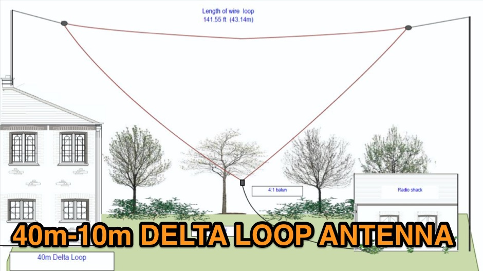 A multi band inverted delta loop antenna project that can be used from 40 to 10 meters band with full details and analysis of antenna performances on each band, document includes EZNec reports and setup pictures
 -
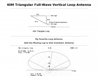 A 40 meters band full wave antenna project plan with model, adding the Missing Leg to the Inverted-L Antenna
 -
 Building a directional antenna for limited space, M0MRR shares his experience constructing a 10-meter Moxon rectangle. Initially using fiberglass fishing poles and a plastic breadboard, he achieved a 1:1.2 SWR across the band with 50 watts, making contacts as far as PY2TO from the UK. The design incorporates 10-amp power cable for elements and RG58 coax with crocodile clips for feeding, demonstrating a cost-effective approach. His field observations confirm the directional properties, noting European signals fading when facing Stateside, and receiving better reports from stations in the antenna's favored direction. While not formally measured, the front-to-back ratio appears effective. The initial build was somewhat flimsy, intended for temporary deployment, but proved effective for DX. Later, M0MRR constructed a more robust 10-meter Moxon using tubular aluminum pipe, indicating an evolution in his design approach for durability. The project highlights practical antenna building for small backyards, emphasizing the benefits of a directional antenna even with modest power.
 -
 HF multiband mini delta compact and easy assembling antenna that cover from 20 to 10 meters by GM3VLB
 -
 A dual-bander for 80M and 40m. An Extended Double Zepp (EDZ) is a 5/4 wavelength center-fed dipole. This article will introduce the Half-Extended Double Zepp (HEDZ) which has characteristics that a lot of amateur radio operators should find quite interesting
 -
 This drawing shows a simple 10 meter wire J-pole antenna designed for 28.4 MHz. It is a vertical, end-fed Zepp-style antenna made from common materials and intended for easy home construction. The main radiating element is a straight length of stranded copper wire, either 14 or 18 gauge, cut to about 16.5 feet. At the top, the wire is supported by an insulator, allowing the antenna to be hoisted vertically. The matching section is made from 450-ohm ladder line, approximately 7 feet 9.5 inches long, and shorted at the bottom. This matching stub transforms the impedance so the antenna can be fed with coaxial cable. The feed point is tapped about 6 inches above the bottom of the stub, with the shield and center conductor connected at the proper points. A choke balun is formed with five turns of RG-58 coax in a 4-inch diameter loop to help reduce unwanted RF on the feed line. The drawing notes that this antenna has about 0 dBd gain, similar to a dipole, but offers an omnidirectional pattern and low-angle radiation when installed high. Its main advantage is practical performance, simple construction, and effective coverage for 10 meter operation.
 -
 The 20-meter homebrew **Moxon antenna** project by 9Y4DD, Dave, details the construction of a 14 MHz directional antenna using readily available and repurposed materials. Initial SWR readings at 6 feet were 1.2 at 14.000 MHz, 1.4 at 14.350 MHz, and 1.1 at 14.175 MHz, with a subsequent increase of 0.1 on all frequencies when raised to 15 feet. The design adheres to specifications provided by L.B. Cebik (W4RNL). Key components include a discarded domestic water pump pressure tank as the center mounting bracket, 1/2-inch PVC conduit for spreaders, and 1/2-inch CPVC hot water pipe inserts to enhance rigidity. The total weight of the antenna is 12.625 pounds, with a material cost of U.S.$36.63. The spreaders are 165 inches from the center, utilizing 2.5mm sq. stranded copper wire for the elements. Dave's design incorporates hexagonal 'spider webs' of waxed twine to stabilize the flexible PVC spreaders, addressing initial issues with wind-induced movement. Separators cut from 3/16-inch Plexiglas maintain an 8.6-inch element spacing. The antenna demonstrated effective DX contacts with Europe from Trinidad, showing improved noise reduction compared to an inverted V.
 -
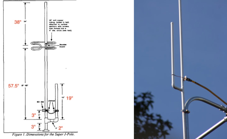 Homebrew a j-pole 2mt and 70 cm antenna project. Make it cheap. This article includes homebrewing instructions, parts lists, tools needed and printable documentation.
 -
 M1PAF's 20 Meter Vertical Moxon antenna design, based on Pete Mills' EZNEC model, utilizes a push-up GRP mast and Tufnol plate for mounting cross arms, minimizing metallic elements within the beam. Hydraulic pipe clamps, also plastic, secure the tube clamps, with only two bolts and a plate being metallic. Dog bone insulators with Kevlar line and snap links facilitate quick wire element attachment, ensuring tension in all dimensions. The antenna's support structure includes Tufnol guying rings for Kevlar guys, providing stability against high winds. The cross arms are constructed from three 1-meter sections, allowing for convenient packing. This portable setup was successfully deployed adjacent to the ocean, enabling over 4500 QSOs in six days with 100W, achieving easy contacts into Japan and Asia. The design emphasizes ease of erection by a single operator and robust performance in challenging environments. Components for the cross arms were sourced from Spiderbeam. Further information is available via M1PAF's QRZ.com details.
 -
 Over 30 distinct shortwave (SW) receiver models are reviewed, offering insights into their performance, features, and user experiences. These evaluations, contributed by readers of the Usenet newsgroup **Rec.radio.shortwave**, cover a wide array of portable and tabletop radios, including popular units like the Grundig YB-400, Sony ICF-SW77, and various Realistic DX series models. Each review details aspects such as frequency range, tuning steps, SSB functionality, antenna performance, and construction quality, often comparing them to other receivers or ham transceivers like the Icom 725. For instance, the Grundig YB-400 review highlights its 144-30000 kHz AM/SSB coverage, direct keypad entry, and 40 station memories, noting its useful narrow bandwidth and tone switch for adjacent signal separation. It also discusses the **SSB mode** stability and the limitations of its 1 kHz frequency resolution for precise zero-beating. The review further details antenna performance, including the effectiveness of the built-in whip, the provided 7m reel antenna, and the potential for overload with larger outdoor antennas. Other reviews delve into specific issues, such as the Sony ICF-SW77's frequency display inaccuracies and timer malfunctions, or the Realistic DX-342's compact size and surprisingly good MW DXing capabilities despite its analog tuning. The collection provides practical, user-generated feedback on sensitivity, selectivity, audio quality, and ergonomic features, helping shortwave listeners understand the real-world performance and quirks of these receivers.
 -
 SM0DTK's 40-meter Moxon antenna project details the construction and deployment of a wire Moxon rectangle, specifically dimensioned for the 7 MHz band. The resource outlines the use of a _Moxon Rectangle Generator_ for calculating wire lengths and the fabrication of plexiglass supports for corners and the feeding point. It describes the practical challenges of elevating the antenna to approximately **14 meters** using an aluminum tube and fiberglass rod, emphasizing the adjustment process for achieving the correct rectangular shape. The article presents comparative results against a 60-meter long-wire and a full-size 40-meter ground plane antenna. The Moxon demonstrated significant directional gain towards the west, facilitating DX contacts in the Caribbean with **100 watts**, while simultaneously reducing QRM from strong eastern European stations. The SWR was reported as perfect without the need for an antenna tuner, validating the design's effectiveness for targeted signal enhancement and interference mitigation.
 -
 This resource details the construction and feeding of a vertical Moxon antenna specifically designed for the 20-meter band (14 MHz). It addresses the common issue of impedance variations at the feed point of vertical dipoles and Moxons, which typically requires the coax to exit at a specific angle (45-90 degrees) to maintain a good 50-ohm match. The presented solution involves opening the lower corner of the fed element and utilizing a transformer for impedance matching, simplifying installation and improving SWR. The alternative feeding method provides a stable match, eliminating the need for precise coax routing to achieve a low SWR. This design offers a practical improvement over conventional vertical Moxon feeding, making deployment significantly easier. The author, SM0DTK, confirms the efficacy of this setup, noting its fine performance and reduced installation complexity compared to traditional methods.
 -
 Article by DK5WL describes a multi-band DX antenna for the 160m-40m amateur radio bands with low visibility but great performance for long distance communication.
 -
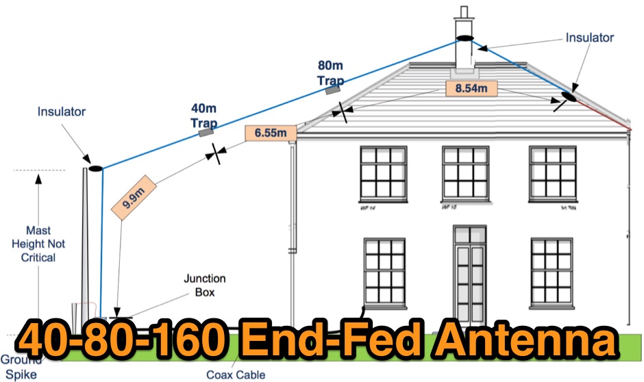 This PDF File desscribes how to homemade a multi-band end-fed trapped wire antenna resonating on the low bands of 160 80 and 40 meters. Contains trap design instructions and some construction tips.
 -
 This article addresses the subject of obtaining the best signal transfer from an antenna to the typical 50-ohm receiver input over a wide frequency range, with emphasis on medium-wave (500 - 2000 kHz), encompassing the standard AM broadcast band and the 160-m amateur band.
 -
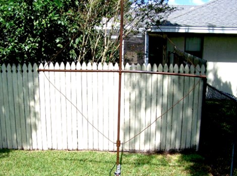 This document by W4HM explains the construction and usage of a 160 meter balanced coaxial receiving loop antenna, which can be easily adapted for the 40 and 80 meters bands. The content provides detailed instructions on building the antenna, its advantages, and how to optimize its performance for amateur radio operations. It is a valuable resource for radio amateurs looking to improve their receiving capabilities and enhance their overall radio communication experience.
 -
 Review of the W5GI Multiband Mystery Antenna by July 2003 Issue of CQ Amateur Radio
 -
 Over 40 years of experience inform the reviews and commentary presented on Dave's Radio Receiver Page, covering a wide array of radio receivers and transceivers. The resource details specific models such as the **ICOM IC-R8600** SDR Communications Receiver, which is lauded as Icom's best wide-band receiver, even surpassing the IC-R9500 in performance. Other notable reviews include the ICOM IC-7300 HF Transceiver, highlighting its direct sampling SDR technology and spectrum scope capabilities, alongside numerous models from Japan Radio Co. (JRC), Kenwood, Yaesu, and various portable shortwave receivers. The content provides practical insights into the performance and characteristics of each radio, often drawing comparisons between models. For instance, the early issues with the AOR AR7030 receiver's Bourns mechanical encoders are thoroughly documented, including AOR's eventual switch to higher-quality Alps encoders. The page also features reviews of antennas like the MFJ-1026 Noise Canceling Signal Enhancer and various power supplies, offering a holistic view of radio monitoring setups. The author's "2 ear / 2 eye method" emphasizes real-world listening experiences over laboratory measurements, providing a unique perspective on equipment utility.
 -
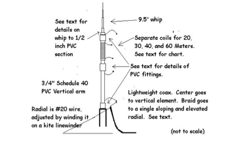 W3FF article about the buddistick portable vertical antenna in a PDF file
 -
 An interesting article on NVIS antennas, explaining basics of NVIS antennas and the main usage of this particular aerials by Patricia Gibbons
 -
 The resource details the construction and performance of a dual-band 40/30 meter _Moxon_ antenna, evolving from an initial single-band 30-meter design that failed in a storm. It specifies materials such as four 10-meter fishing rods, galvanized iron TV antenna support pipes, 1mm diameter PVC-covered copper wire, and a piece of 75-ohm TV satellite cable for feedline. The document outlines the iterative design process, including initial resonance measurements of 9.9 MHz for 30 meters and subsequent recalculations to shift the center frequency by 300 kHz using _Moxon software_. Initial testing on a roof yielded SWR readings of 1.4:1 at 7.200 MHz and 1.5:1 at 10.280 MHz. After installation atop a 30-meter tower, the final SWR measurements were 1.1 at 7.130 MHz and 1.4 at 10.230 MHz, with a notable 30 dB front-to-back ratio on 40 meters. The 30-meter performance, while good, showed a front-to-back ratio of approximately 15 dB, suggesting a slightly high resonance. The antenna's placement on a 700-meter hill, with a significant ground drop in certain directions, is noted as a potential factor in its excellent DX performance, enabling daily contacts with the USA West Coast on 30 and 40 meters with 100 watts.
 -
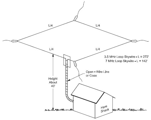 An horizontal full wave wire loop antenna for the 80 meters band by W4HM
 -
 Presents G0GSF Brian's ZS6BKW antenna, a refined iteration of the classic G5RV, offering improved performance across multiple HF bands. The design emphasizes specific radiator and ladder line lengths to achieve lower SWR on 40m, 20m, 17m, 12m, and 10m, making it a practical choice for operators seeking a single wire antenna solution. The document includes critical dimensions for the flat-top and the 450-ohm ladder line section, which are key to its multiband resonance characteristics. Unlike the original G5RV, the ZS6BKW aims for direct 50-ohm feedpoint impedance on several bands, reducing the need for an external antenna tuner. My field experience with similar optimized dipoles confirms that precise construction, particularly the ladder line length, is paramount for realizing the intended SWR benefits. This design offers a compelling alternative for hams with limited space or those preferring a less complex antenna system.
 -
 WA2UGT X-beam antenna for 17 meters band
 -
 Based on a W4TWW project and modified by KN4LF
 -
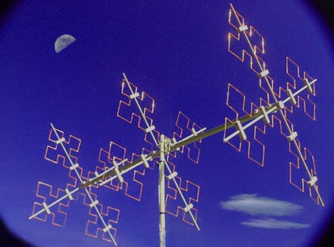 A Quad Fractal Antenna for 20 meters band by F3DD
 -
 This article describes a simple, inexpensive, dipole antenna that will rival the performance of a ten-meter beam.
 -
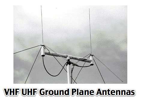 Phased array Ground Planes antennas for 144 Mhz
 -
 Phased arrays of short vertical antennas. A technical notes from Butternut antennas on phased vertical arrays
 -
 The original G5RV antenna system consists of a center-fed horizontal 102' wire plus a 34' length of open-wire 525-Ohm feeder. Louis Varney, the antenna system's developer, intended two other features. Learn more at Cebik website
 -
 A 40-meter reversible _Moxon rectangle_ antenna project details its construction and performance, featuring 51-foot long sides and 7.7-foot turned-in sections. The design incorporates a 16.5-foot boom, with elements spaced 1.1 feet apart, constructed from #14 covered wire. It utilizes two double-pole relays for switching between NE and SW directions, achieving F/B ratios up to 40 dB on CW and 30 dB on SSB, with distinct reflector stub settings for each mode. This antenna replaced a full-size 2-element Yagi, demonstrating comparable forward gain while offering superior F/B ratios and directional flexibility. _EZNEC_ modeling indicates only 0.2 dB less forward gain than the Yagi. The system uses no baluns, relying on half-wave feedlines and switched stubs for impedance matching. The antenna is tree-supported at 45 feet, with its effective radiation height modeled at 80 feet due to local terrain, enhancing its performance over a nearby lake.
 -
 The "Largest YU Moxon" document details the design and construction of a substantial multiband Moxon antenna, primarily for 80m, 40m, and 20m operation. It presents specific design parameters derived from NEC-based simulations, including a 4-element 80m Moxon with 37 dB F/B and 7.81 dBi gain on a 47m boom, a 4-element 40m Moxon with a bidirectional pattern, and a 6-element 20m Moxon optimized for specific side lobes. The resource provides precise element lengths and spacing in meters for each band, alongside measured SWR results across the 3.650-3.800 MHz, 7.000-7.100 MHz, and 14.000-14.350 MHz segments. The construction narrative outlines the challenges and solutions encountered by the YU team, including the use of trees for support, the creation of "ugly" air-choke baluns from RG-58 cable wound on plastic bottles for each band, and the meticulous process of attaching wires to a rope boom. It documents the physical dimensions of the vineyard site (47 x 38m) and the azimuth orientation (340 degrees) chosen for the antenna. The document is distinctively useful for its practical insights into large-scale antenna deployment in a field environment, offering real-world SWR measurements and anecdotal performance reports from CQWW contest operations. It includes numerous photographs illustrating the construction process, the team members, and the finished antenna structure, providing visual context to the technical details.
 -
 The total length of the inverted L is 240 feet, which is 7/16th of a wave length long. It has a 92 foot horizontal linear load section 1 foot above ground that terminates into a home-brewed parallel network tuner by KN4LF
 -
 This PDF document, authored by KT4QW in October 2004, details the construction and modeling of a dual-band, horizontally polarized hanging rectangular loop antenna for **10 and 17 meters**. The design, adapted from *The ARRL Handbook*, utilizes _NEC4WIN95_ software for scaling and optimization, targeting a 50 ohm feedpoint impedance. The resource includes a bill of materials, step-by-step construction instructions, and a discussion of the antenna's radiation characteristics. It presents NEC-generated elevation and azimuth patterns, comparing the loop's performance to a half-wave horizontal dipole at the same height and frequency. The 17-meter element is centered at 18.140 MHz for low SWR across the phone band, while the 10-meter element is centered at 28.500 MHz. Construction involves 14-gauge stranded copper wire and Schedule 40 PVC spreaders, with the total wire length calculated by the formula: Length in feet = 1005/MHz. The feedpoint impedance can be adjusted by modifying the rectangular aspect ratio. The document specifies hoisting the antenna to at least a half-wave above ground for testing. It notes that a balun was tested and found to have no measurable effect on SWR or radiation characteristics. A 2-meter scale model is presented to illustrate the physical design, and a "rotator" string is incorporated for directional adjustment up to 90 degrees.
 -
 Interesting review about active magnetic loop antenna Wellbrook ALA 1530 and 330S by ON4SKY
 -
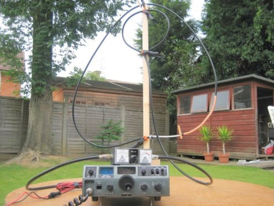 A coaxial cable tuneable magnetic loop antenna for 7MHz. This experimental antenna does not require a tuning capacitor
 -
 KN4LF article about a 1/4 wave fan inverted L antenna for 80 and 160 meters band
 -
 Yaesu's FT817 and Super Antennas MP-1 review by George Heron, N2APB
 -
-
 The document details the optimization and construction of the _Maria Maluca_ antenna, a compact 6-band (20m-6m) directional beam. It presents a comparative analysis of shortwave antenna principles, highlighting the efficiency gains achieved by using an open feeder line and tuner as a resonant unit, contrasting this with the losses associated with traps or capacitive loads in multiband antennas. The resource specifically revisits an older South American 2-element design for 10, 15, and 20 meters, applying modern NEC-based software to develop a six-band version. Performance data is meticulously tabulated, showing impedance, free space gain, gain at 12m height, elevation angle, and front-to-back (F/B) ratio for each band from 20m through 6m. For instance, on 15m, the antenna achieves 5.1 dBd free space gain and 13.72 dB F/B ratio. The construction section provides practical guidance on element assembly using aluminum pipes and hose clamps, detailing the use of a heavy-duty glass fiber reinforced polyamide rod for electrical separation and bending strength. It also specifies the use of 450-ohm _Wireman_ line CQ 552 for the transmission line. The document includes diagrams for rod fixing, an air-wound balun, and a vertical elevation diagram for the 15m band, illustrating its DX qualification. It also discusses the antenna's suitability for portable and expedition operations, noting its compact transport dimensions (max 1.50m length, 12 lb weight) and quick assembly time (under 15 minutes). The author, Dipl.Ing. Helmut Oeller, DC6NY, is identified as a source for material kits.
 -
 W1ZY's 40-meter **Moxon** antenna project details nine months of experimentation, culminating in a reversible array built from No. 12 insulated wire. The design incorporates two RF current baluns and a unique two-wire element construction, where each element consists of two parallel wires spaced 3 inches apart. The resource provides specific dimensions for the first prototype, including A=50.98', B=7.87', C=1.25', D=9.3', and E=18.42', optimized for 7.050 MHz CW operation. It thoroughly explains the construction of custom two-wire insulators from Plexiglas semi-rods and the critical pre-tensioning process required to maintain wire separation and array integrity. The author, Bill, emphasizes the antenna's exceptional receive performance, noting a 30-35 dB front-to-back ratio, which allows for significant signal rejection from the rear. While the Moxon offers 5-6 dB gain on transmit, its primary advantage lies in its ability to radically reduce rear-facing signals on receive, a characteristic Bill believes is often overlooked in transmit-focused comparisons. The guide details a flexible tuning method using removable tail-end jumpers, enabling adjustments to both tail-end and parallel dimensions without re-soldering the feed point, a technique refined over three prototypes.
 -
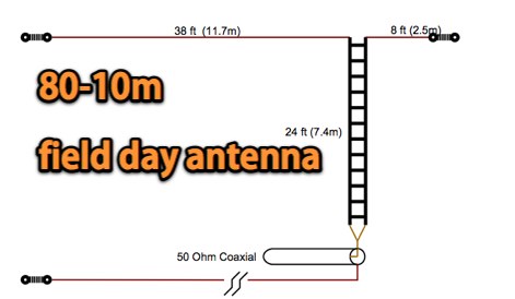 A Compact size 80-10 m field day antenna offering a Low angle of radiation and very easy to build and set up
 -
 Adalet wireless document on antenna basics in a four pages pdf file
 -
 A delta loop antenna for 17 meters band include eznec antenna model file
 -
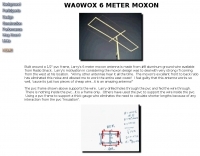 Built around a 1/2" pvc frame, Larry's 6 meter moxon antenna is made from #8 aluminum ground wire
 -
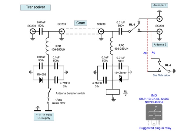 A 2-way remotely operated HF antenna switch, based on an idea supplied by G3YEU