Search results
Query: controlled
Links: 75 | Categories: 1
Categories
-
 Use real audio streams to listen to Hf and VHF stations around the world via remote controlled receivers connected to the web.
 -
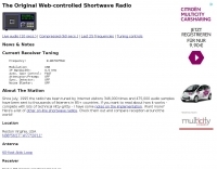 Drake R8 Communications Receiver Reston Virginia, USA. Allow remote control of a DRAKE receiver with a nice interface that permi you to rotate the main tunin knob, set mode and change some key settings.
 -
 Details the construction of a **multiband vertical** antenna, specifically designed for stealth operation in a rented property, covering 80m, 60m, 40m, and 30m. The author, N3OX, leverages a 12m Spiderbeam telescoping fiberglass pole as the primary support, noting its sturdiness compared to typical fishing rods while remaining light enough for quick deployment and takedown. The radiating element is a 14 gauge Flex-Weave wire, attached to the pole's top with a rubber grommet, and fed by 27 bare 18 gauge radials spread across a 40-foot square backyard. N3OX describes the impedance matching solution, opting for custom-built L-networks over a remote tuner to enable fast bandswitching. Using an MFJ-259B and EZNEC modeling, base impedances were measured and component values calculated with G4FGQ's L_TUNER and SOLNOID_3 programs. The 80m coil is wound on a 3.5-inch PVC form, while the 30m, 40m, and 60m coils are air-wound, self-supporting #10 wire. Variable capacitors are incorporated for 40m and 30m shunt elements, with the 60m impedance matched by a series inductor. The project includes a **servo-controlled** homebrew band switch, utilizing a two-pole 12-position ceramic wafer switch for remote operation, addressing the limited 80m bandwidth. The entire matching network is housed in a weather-resistant shelter constructed from lumber and aluminum flashing. N3OX reports good DX results at 100W, estimating the total cost between $150 and $250, depending on existing parts.
 -
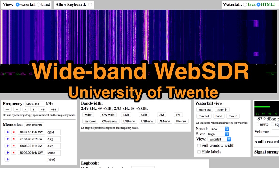 On this page you can listen to and control a short-wave receiver located at the amateur radio club ETGD at the University of Twente. In contrast to other web-controlled receivers, this receiver can be tuned by multiple users simultaneously, thanks to the use of Software-Defined Radio. Provided by PI4THT
 -
 Grig is a freeware simple Ham Radio control (CAT) program based on the Ham Radio Control Libraries (Hamlib). It is intended to be highly generic presenting the user to the same graphical user interface regardless of which radio is being controlled. Grig supports the most commonly used CAT commands that are implemented by Hamlib, and integrates well with other ham radio programs like Xlog and gMFSK. Grig has been developed on Linux, but has been ported on Mac and Windows OS.
 -
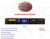 You can listen to a remote controlled ham radio station and if you are a authorized ham you can talk. Originally hosted at lamonica.com this is one of the very first online ham radio stations on the net.
 -
 GlobalTuners provides access to remotely controlled radio receivers over the internet. You can listen to ham radio, shortwave radio, air traffic control, airband, ACARS, airports and much more. Tune remotely controlled receivers from all over the world with your browser and listen live.
 -
 Demonstrates the construction of a **remote antenna tuner** utilizing a standard radio-controlled (RC) servo mechanism to adjust a variable capacitor. The design focuses on enabling remote tuning for narrow-bandwidth antennas, specifically mentioning frame and packing crate antennas, from within the shack. It covers the mechanical arrangement for integrating the servo with a capacitor and provides a circuit diagram for a control unit that generates the necessary 0.5mS to 1.5mS pulse-width modulation (PWM) signals to drive the servo's 180-degree rotation. This setup was successfully tested with up to 20 watts RF power without arcing or adverse effects on the servo, though tuning was performed at 1 watt for VSWR readings. The resource highlights the use of inexpensive, readily available components, such as Futaba servos, and details critical considerations like power supply decoupling with a 47uF capacitor to prevent unintended servo movement upon power-off. The system provides a practical solution for optimizing antenna performance for specific frequencies without manual adjustment at the antenna itself.
 -
 This program descrambles band inverted encrypted transmissions, usually found on VHF/UHF. It uses a NCO (numerical controlled oscillator) to re-produce the originally inverted audio band. Use it only if legally permitted in your country. I assume no responsabilities deriving from its use. Standard disclaimer applies
 -
 GlobalTuners provides access to web controlled receivers. Listen to Ham radio, Tune Shortwave radio, Listen to Air traffic control, experience Airband receptio including ACARS and Airports. Tune remotely controlled receivers all over the world with your browser and get live audio.
 -
 Presents a crystal-controlled CW transmitter design for the 40-meter band, delivering 5 to 7.5 watts output power. The circuit innovatively employs an _IRF510_ power MOSFET in the final amplifier stage, diverging from conventional bipolar transistors. This design offers high gain, nearly 90% efficiency, and robust resistance to high SWR, allowing 30-second key-down operation into an open circuit without damage. A critical aspect is the precise adjustment of the MOSFET gate bias via a 10K trimmer pot, _R10_, to maintain quiescent current between 5 and 10 mA, preventing thermal runaway inherent to bipolar devices. The prototype was constructed on a _Radio Shack universal board_ and achieved immediate operational success. The design requires a 15-volt Zener diode to protect the MOSFET gate from overvoltage. Component sourcing information is provided, including specific crystal frequencies (7.040 MHz or 7.122 MHz) available from _Dan’s Small Parts & Kits_ or Doug Hendricks. The fixed frequency can be slightly adjusted with a trimmer capacitor. A complete bill of materials, including resistor values, capacitor types, toroid specifications, and transistor part numbers, is detailed, alongside a clear schematic diagram.
 -
 manufactures and distributes HF, VHF, UHF and SHF equipment covering 10MHz. - 47.0GHz. Our products include: Wireless LAN / WAN Bidirectional Linear Amplifiers, Low Noise Preamplifiers - LNA's, RF Linear Amplifiers, Relays, Transverter Systems, Frequency Translation Systems, Downconverters, Antennas, Parabolic Dishes, Coaxial Cable, Relays, Antenna Switches, Microwave Test equipment, PC controlled Receivers, Microwave Linear Amplifiers including models for Telemetry, Wireless, and CDMA applications.
 -
 The "EZ-Tuner" is a homebrew automatic legal-limit antenna tuner that covers all amateur HF bands from 160-10 meters. Using a T-network design and controlled by a BASIC Stamp BS2sx microcontroller, the EZ-Tuner will match at least a 16:1 VSWR for either unbalanced or balanced transmission lines.
 -
 This program descrambles band inverted encrypted transmissions, usually found on VHF/UHF. It uses a NCO (numerical controlled oscillator) to re-produce the originally inverted audio band.
 -
 Control an ICOM PCR-100 and listen to the audio stream. This web controlled receiver si based in the Netherlands by PA3ANG and offer 10kHz - 1300MHz in AM, FM, FMW
 -
 Operating within the amateur radio HF spectrum requires adherence to established band plans and considerate practices. This guide from the ARRL outlines commonly accepted frequency ranges for specific modes and activities, spanning from 1.800 MHz to 29.680 MHz. It delineates segments for **CW**, **SSB**, RTTY/Data, SSTV, Digital Voice, and AM operations, including dedicated QRP calling frequencies and DX windows. The document emphasizes that these are not regulatory mandates but rather widely recognized conventions, acknowledging that high-activity periods like DXpeditions or contests may lead to temporary deviations. It explicitly references Section 97.101(b) of the FCC Rules, asserting that no station holds exclusive rights to any frequency. The guide also lists frequencies for IBP/NCDXF beacons and automatically controlled data stations. Practical advice is provided regarding frequency selection, stressing the importance of checking for existing use before transmitting. It also mentions ARRL band plans for frequencies above 28.300 MHz, directing operators to additional resources.
 -
 If you can't get on the air from home, the Internet may provide the answer. By Brad Wyatt, K6WR. Pdf File.
 -
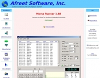 Simulates a **CW** contest environment, presenting operators with realistic scenarios for improving their receiving and sending proficiency under pressure. The software generates varying signal-to-noise ratios, QRM, and QRN, replicating conditions encountered during actual **DX** contests. Users practice copying callsigns, exchange information, and manage pileups, with customizable parameters for speed and difficulty. The program provides immediate feedback on accuracy and speed, allowing for targeted skill development in a controlled setting. It supports various Windows operating systems, from Windows 95 through Windows 10, and can also run on macOS using Wine.
 -
 USB-Controlled Synthesizer for Softrock RXTX and Local Oscillator Applications
 -
 A full line of single-channel synthesized and crystal controlled vhf and uhf fm receivers. Great for repeaters, telemetry, and control applications.
 -
 This resource details the construction of a versatile CW/QRSS beacon, designed around a Microchip _PIC16F84_ microcontroller. The project provides a flexible platform for transmitting either standard CW or very slow QRSS signals, making it suitable for LF, VHF, UHF, and SHF applications. It supports two distinct messages, each configurable for speed (from 0 to **127** WPM for CW, or up to **127** seconds per dot for QRSS) and repetition within a six-phase sequence. The core functionality relies on the PIC's EEPROM, which stores all operational parameters, including message content, transmission speeds, phase configurations, and relay control settings. This design allows for parameter modification directly via programming software like _ICProg_ without altering the main program code. The project includes a detailed schematic, a component list, and an explanation of the EEPROM memory mapping for messages, speeds, phase settings, and inter-phase delays. General-purpose outputs (OUT1, OUT2, OUT3) provide dry relay contacts for external control, enabling functions such as power switching, antenna selection, or frequency changes. A 'TRIGGER' input facilitates controlled starts or continuous free-run operation. Sample EEPROM configurations illustrate how to program specific beacon sequences, including message content and relay states.
 -
 Constructing a functional spectrum analyzer for the 0-100 MHz range presents a significant challenge for radio amateurs, often requiring specialized components and careful calibration. This project details a homebrew spectrum analyzer design utilizing common integrated circuits like the _SA605D_ FM receiver IC and _MAR-6_ MMIC amplifiers, aiming for a cost-effective solution. The design incorporates a low-pass filter, RF amplification, a voltage-controlled oscillator (VCO) for downconversion, and multiple IF stages at 150 MHz and 10.7 MHz, with a resolution bandwidth (RBW) of 15 kHz. Critical components such as the _SBL-1_ mixer and varicap diodes are specified, alongside instructions for winding inductors and tuning filters. The analyzer's performance is discussed in terms of input level limitations, specifically the 1dB-compression point and third-order intercept point, to ensure accurate measurements and prevent component damage. The _SA605D_'s logarithmic Received Signal Strength Indicator (RSSI) output serves as the detector, driving the Y-input of an oscilloscope, while a _TL084_ op-amp generates the sweep signal for the X-input. Potential enhancements include adding a step attenuator, improving front-end filtering, and implementing switchable IF filters for variable RBW, allowing for greater versatility in analyzing RF signals.
 -
 Remotely controlled antenna switch that can switch between 5 antennas
 -
 One specific challenge in the KazShack, operating Single Operator Two Radios (SO2R), involved sharing a K9AY receive antenna between two transceivers without direct RF connection or manual feedline swapping. The solution, detailed in this project, adapts the **W3LPL RX bandpass filter** design to split 160m and 80m signals, feeding them to separate radio inputs while maintaining isolation. This approach also addresses the issue of strong broadcast band interference from a nearby 50KW WPTF transmitter on 680kc. The construction utilizes T-50-3 toroids and NP0 ceramic capacitors, built in a "dead bug" style on copper clad board. Each band's filter coils are identical and resonated to the desired frequency using an MFJ-259 antenna analyzer. A single DPDT relay, controlled by a remote toggle switch mounted on an aluminum panel, facilitates quick band switching between radios, simplifying low-band operations. While some signal loss is noted, the expected lower noise levels from the receive antenna are anticipated to compensate, potentially reducing the need for constant volume adjustments during toggling between transmit and receive antennas.
 -
 glfer is a program for reception and transmission of QRSS/DFCW signals. It is composed of two main parts: the spectrogram window, where you can see the spectrum of the received signal vs. time the transmission functions, to emit cw characters at a slow but precisely controlled speed, using the QRSS (slow CW) or DFCW (Dual Frequency CW) modes
 -
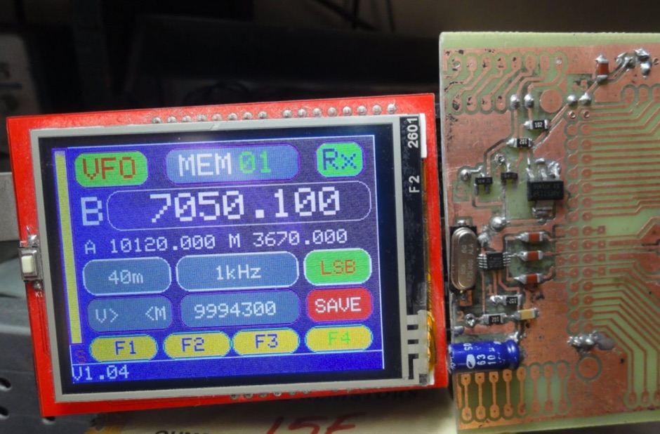 Arduino uno universal VFO/BFO with Si5351 and TFT touch screen for BITX like txcvr
 -
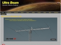 Electronically controlled HF antennas. General coverage. Top features on all ham bands. Very advanced materials and state of the art technology.
 -
 Grig is a simple Ham Radio control (CAT) program based on the Ham Radio Control Libraries (Hamlib). It is intended to be highly generic presenting the user to the same graphical user interface regardless of which radio is being controlled.
 -
 Cheap UHF antenna plans for 2 meters and up including 421 1296 and 902 Mhz
 -
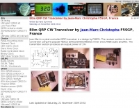 Crystal-controlled QRP tranceiver by F6BCU for 80 meters band 1W output
 -
 Presents a QRP AM/CW transmitter project specifically designed for the 10-meter band, utilizing a crystal oscillator and a collector-modulated AM oscillator. The design employs a 2N2219(A) transistor in a Colpitts configuration, generating 100 to 350 mW of RF output power depending on the 9-18 Volt supply voltage and modulation depth. Frequency stability is maintained by a 28 MHz crystal, with fine-tuning possible via a Ct1 trimmer capacitor for approximately 1 kHz adjustment. The resource details the RF oscillator stage, implemented with a 2N2219 NPN transistor, emphasizing frequency stability and low power dissipation. It also covers the amplitude modulation stage, managed by a 2N2905 PNP transistor, which impresses audio information onto the carrier. Selective components (C3, C4, C7, C5) enhance voice frequencies within a +/- 5 kHz bandwidth, and modulation depth is controlled by R2 and R3. The project includes a 3-element L-type narrow bandpass filter (Ct3, L3, C10) to suppress harmonics and ensure a clean output signal. The project provides a complete schematic diagram, a comprehensive parts list including specific capacitor, resistor, and inductor values, and construction notes for the coils (L1, L2, L3). It also offers practical advice on enclosure requirements, suggesting an all-metal case or a PVC box with graphite paint for RF shielding. Operational parameters such as current draw (27mA@9V to 45mA@16V) and input impedance (50 Ohms) are specified, alongside guidance on antenna matching and the importance of a valid amateur radio license for 10-meter band operation.
 -
 The Remote Control Antenna Switch consists of two circuit boards. The control unit and the remotely controlled switch
 -
 An example of how to control a Yaesu FT-817 with an Arduino to make a multi-band CW beacon.
 -
 This page describes an cheap RF signal source, a portable micro beacon, using a low cost temperature controlled crystal oscillator
 -
 A large collection of crystal controlled scanners
 -
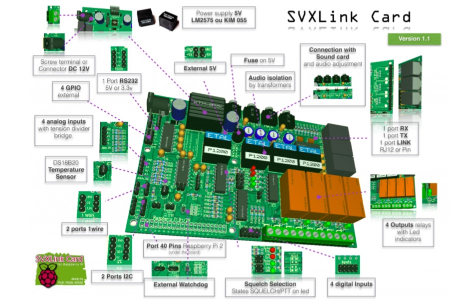 This electronic board will be installed over a Raspberry Pi CPU card to provide a repeater controler. All features are software controlled with the famous SVXLINK and other interessed modules.
 -
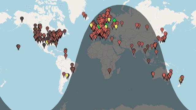 A live map of current KiWiSDR receivers available on the network. It allows users to explore a directory of web-controlled receivers for listening to HF and VHF stations worldwide. The site provides access to remote ham radio stations online, making it a valuable resource for amateur radio operators.
 -
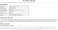
 The resource details the construction of a homebrew 50-watt FET amplifier, based on Don W6JL's _QST Homebrew contest_-winning design from 2009. It functions as an afterburner for QRP transceivers, providing a **12dB** power lift. The amplifier utilizes IRFZ24N FETs and covers the 80, 40, 30, and 20-meter bands, with the 20m LPF extending to 17m. Key technical aspects include an FT37-43 transformer for the input network, a relay-switched 3dB pad for lower bands controlled by an _Arduino Nano_, and an RF-actuated T/R switch. The LPF board integrates four relay-switched filters rated for 50 watts, using capacitors with a minimum 250VDC rating. Performance measurements indicate a power gain ranging from **4.4dB** on 20m to 8.1dB on 80m, with a required drive power of approximately 5 watts. The article also discusses thermal management, current limiting considerations, and component sourcing.
 -

-
 Operating magnetic loop antennas requires careful consideration of RF safety, particularly regarding near-field magnetic field intensity. This resource presents calculations for magnetic field strength (H-field) at various distances from a magnetic loop, emphasizing that the H-field is significantly higher than the E-field in the near-field region due to the inductive nature of the radiating element. It provides specific formulas and examples for determining safe operating distances based on power levels and loop dimensions, crucial for compliance with RF exposure limits. The analysis compares calculated H-field values against FCC and ICNIRP maximum permissible exposure (MPE) limits for controlled and uncontrolled environments. It demonstrates that even at QRP power levels (e.g., 5W), the H-field can exceed MPE limits within a few feet of the antenna, necessitating greater separation distances than often assumed for electric field considerations. The practical application of these calculations helps amateur radio operators configure their stations to ensure personnel safety and regulatory compliance when deploying compact, high-Q magnetic loop antennas.
 -
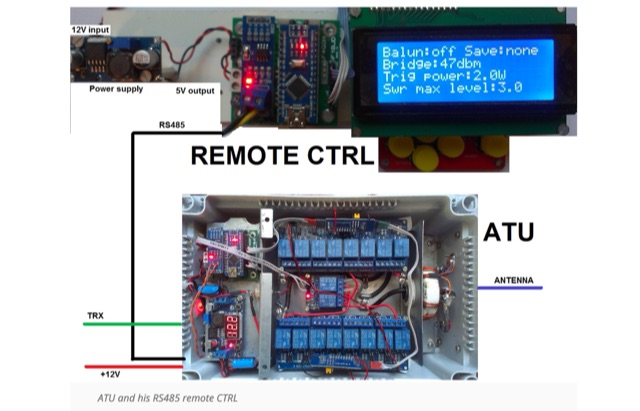 Make and automatic antenna tuner based on Arduino and using economic card. This ATU Project can be installed outdoors and controlled remotely by an rs485 link
 -
 MiniDSP is a platform for digital audio signal processing applications. Manufacture low cost digital signal processor kits for the DIY/OEM market. Our flexible audio platforms are software controlled and easily upgradeable.
 -
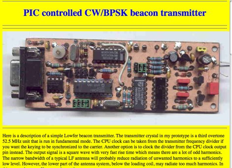 A description of a simple Lowfer beacon transmitter.
 -
 A synthesized 2.3 GHz Amateur Television (ATV) transmitter design, conceived by Ian G6TVJ, is presented, targeting broadcast-quality video performance on the 13cm band and extending up to 2.6 GHz. The core of the design utilizes a commercial Z-comm Voltage Controlled Oscillator (VCO) that tunes from 2.2-2.7 GHz, providing a +10 dBm output and simplifying RF alignment. This VCO's stability, originally intended for narrowband applications, readily accepts high-frequency video modulation, contributing to the transmitter's robust performance. The exciter stage, incorporating a Mini Circuits VNA 25 MMIC amplifier, boosts the signal to +16dBm, while a Plessey SP4982 prescaler divides the output frequency for the synthesizer. The synthesizer employs a Motorola MC145151 CMOS parallel IC, favored over the common Plessey SP5060 for its superior video modulation characteristics and ease of programming without microprocessors. This choice addresses issues like LF tilt and distorted field syncs often seen with SP5060 designs, particularly when operating through repeaters or over long distances. The MC145151 divides the signal further, enabling precise frequency stepping, with programming handled by EPROMs for channel selection and LED display. The loop filter network, critical for video integrity, was developed through experimentation to prevent the PLL from reacting to video modulation, ensuring a clean transmitted picture. The transmitter incorporates a Down East Microwave commercial power amplifier module, delivering approximately 1.6W output, driven by the exciter through a 3dB attenuator. Construction involves surface-mount SHF components on micro-strip lines etched onto double-sided fiberglass board, housed within a tinplate box. The design boasts no AC coupling in the video path, preserving low-frequency response, a common failing in other ATV transmitters. Performance tests with a 50Hz square wave revealed no LF distortion, and a calibrated "Pulse & Bar" signal showed a near 100% HF response, demonstrating its capability for high-quality ATV transmissions.
 -
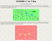 Vasantha VU2VWN VFO controlled 40m Tansmitter schematics
 -
 This processor controlled autoranging sniffer has become popular for vehicle based foxhunting in Australia
 -
 FMI provides superior solutions in the design and manufacture of frequency control devices including Voltage Controlled Temperature Compensated Crystal Oscillators (VCTCXO), voltage controlled crystal oscillator (VCXO), Temperature Compensated Crystal Oscillators (TCXO), crystal clock oscillators, high temperature oscillators, surface mount and crystal oscillator products, phase locked sources and more.
 -
 This project details the construction and testing of a M0PLK Delta Loop antenna for the 20-10m ham radio bands. Inspired by positive reviews highlighting its reduced local QRM compared to Cobweb antennas, the author built the antenna using aluminum tubes, DX-Wire FS2 wire, and a 1:4 balun. A mix of custom 3D-printed parts and careful assembly ensured stability and performance. Initial VSWR measurements met expectations, and test QSOs demonstrated success across multiple bands. Future enhancements include adding a lightweight, remote-controlled rotator for directional capabilities.
 -
 An interesting article about amateur radio portable operations with excellent pictures. Setup includes a 60 watts of portable solar power being controlled by a charge controller, and a batteries powering an FT-897D.
 -
 Constructing a high-performance RF spectrum analyzer up to 1000 MHz requires careful attention to component selection, shielding, and circuit isolation. This resource details a project that improves upon the _Spectrum Analyzer for the Radio Amateur_ design by Wes Hayward (W7ZOI) and Terry White (K7TAU), incorporating ideas from Scotty Sprowls' project, particularly his 1013.3 MHz IF bandpass cavity filter. The analyzer utilizes a Mini-Circuits SRA-11 mixer with a sweeping local oscillator from 1013 to 2013 MHz, feeding into a 4-pole copper pipe cavity filter. The design employs a second SRA-11 mixer with a fixed 1024 MHz LO to produce a 10.7 MHz final IF. This signal then passes through narrowband resolution filters and is processed by Analog Devices AD603 and AD8307 ICs for IF amplification and logarithmic detection, driving an oscilloscope in X/Y mode. The project emphasizes modular construction, using salvaged components and double-sided FR4 material for PCBs, with critical notes on minimizing spurious images through effective shielding and proper voltage regulation for each module. Key components include a Z-Communications V585ME48 VCO for the first LO and a Z-Comm V583ME01 VCO controlled by a Motorola MC145151 PLL for the second LO. An optional Hittite HMC307 step attenuator and K&L 5L121-1000/T5000-O/O low-pass filter manage RF input. Tuning procedures for the 10.7 MHz IF resolution filter are also detailed, showing before-and-after spectrum views.