Search results
Query: design dimensions
Links: 140 | Categories: 0
-
 This guide provides step-by-step instructions for constructing a tin can waveguide antenna, commonly known as a cantenna, for enhancing WiFi signal range. The project is budget-friendly, costing under $5, and utilizes easily accessible materials like a food can and basic electronic components. The design is suitable for 802.11b and 802.11g wireless networks, operating within the 2.4 GHz frequency range. To start, gather the necessary parts including an N-Female chassis mount connector, nuts, bolts, and a suitable can. The assembly process involves drilling holes in the can for the connector and mounting the probe. The guide emphasizes the importance of can dimensions and placement for optimal performance, encouraging experimentation for best results. This project is ideal for amateur radio operators and DIY enthusiasts looking to improve their wireless connectivity without significant investment. Safety precautions are advised, as the author does not hold electrical engineering credentials. Users are encouraged to take responsibility for their equipment and ensure proper assembly. With this simple yet effective antenna, users can extend their WiFi coverage and enjoy enhanced connectivity.
 -
 The Super Loop Antenna page, designed by Jim W4FTU, provides detailed information on the RadioWorks \'Superloop III\' antenna as an alternative for operators with limited space. The page discusses the physical variations of the antenna, including dimensions and materials used, as well as its electrical characteristics such as the 30\' ladder line. The content is useful for amateur radio operators looking for antenna options for the 80 and 40 meter bands, especially those with small lots or zoning restrictions. The page is well-organized and informative, making it a valuable resource for antenna enthusiasts.
 -
 Cubic quad antennas are renowned for their high gain, excellent front-to-back ratios, and low angles of radiation, making them a popular choice among amateur radio operators. This resource provides detailed designs for constructing cubic quads optimized for 2, 6, 10, 12, and 15 meter bands. The lightweight structure can be easily built using fiberglass tubes and central hubs, allowing for portability and ease of assembly. The article discusses the specific dimensions and configurations required for both HF and VHF applications, emphasizing the importance of proper spreader lengths and boom dimensions. It also highlights the challenges of assembling larger cubic quads in limited spaces, offering practical solutions for hams with smaller backyards. With a focus on multi-band operation, this guide serves as a valuable resource for both novice and experienced operators looking to enhance their antenna systems.
 -
 Dissects the internal components of the popular _Antron 99_ vertical antenna, revealing its unique design elements. The analysis details the construction of the coaxial phasing sections, which contribute to its multi-band performance across 10, 12, 15, and 17 meters. Observations include the use of fiberglass tubing for weather protection and the specific arrangement of conductors within the antenna's structure. The examination highlights the antenna's reliance on a series of coaxial stubs to achieve resonance on multiple HF bands without external tuning. This internal architecture provides insights into how the _Antron 99_ manages impedance matching and radiation patterns for effective DX operation. Further details cover the antenna's base mounting and overall physical dimensions.
 -
 Sixty-four years of operating experience inform Glynn E. "Buck" Rogers Sr., K4ABT's, insights into the J-Pole antenna, which he describes as a direct descendant of the _Windom_ or _ZEPP_. His first article on the J-Pole appeared in HRC magazine in 1958, and he has since published numerous pieces in publications like CQ Magazine, consistently referring to the J-Pole as a Windom with a folded-back short section forming the parasitic element. He emphasizes that both the Windom and J-Pole are powerful multi-band antennas, performing exceptionally well at harmonics of their fundamental design frequency, and advocates for 50-ohm coaxial cable with a _BALUN_ at the feed-point to avoid RF energy losses. K4ABT details the J-Pole's features, noting its ease of erection, lack of radials, low angle radiation, greater bandwidth, and immunity to terrestrial noise. He highlights its suitability for local nets and distant repeaters, claiming more gain and durability than most ground planes, and its ability to meet stealth antenna requirements. The guide provides specific dimensions for 2-meter (145.000 to 146.000 MHz) and 6-meter (50.500 to 51.500 MHz) J-Pole antennas, including measurements for the long driven element, short tuning stub, and spacing. The construction section illustrates a modified feed technique using an SO-239 chassis-mount coax connector soldered into a copper tee, deviating from the usual hose clamp method. The author also discusses the use of _EMT_ (electrical metallic thin-wall conduit) as an alternative to copper in earlier days. He cautions against building a 75-meter J-Pole due to its impractical length, reinforcing the antenna's optimal application for VHF and UHF bands.
 -
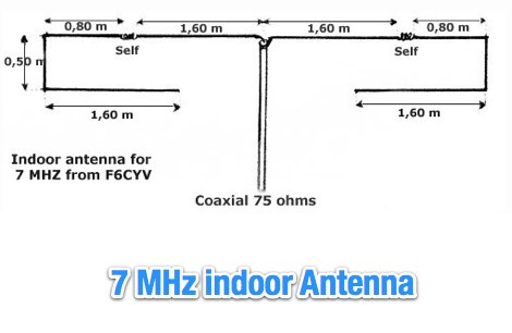 The page provides a project for an indoor wire antenna for the 7 MHz band, based on a design by F6CYV. It aims to help amateur radio operators lacking space to set up an antenna for 40 meters. The author shares their experience using the antenna inside an apartment, noting good reception of European signals and contacts with over 150 countries. The project details the materials and dimensions needed for the antenna, along with tips for optimal performance.
 -
 The J-Pole Antenna Design Calculator, developed by K4ABT, G.E. "Buck" Rogers Sr., facilitates the rapid determination of J-Pole antenna dimensions for various amateur radio bands. Users input their desired operating frequency to generate specific measurements, enabling construction for HF, 2 meters, 220 MHz, 440 MHz, and higher frequencies. The tool supports designs using materials like aluminum or copper, offering flexibility for homebrew enthusiasts. Operational guidance includes recommendations for integrating a **choke balun** near the feedpoint to mitigate RF on the feedline, thereby improving SWR accuracy. For 2-meter operation, a suggested choke configuration involves four turns of coax with a 5-inch diameter, positioned within 3 to 4 inches of the feedpoint. Additional builder hints detail cost-effective construction methods, such as utilizing 1/2-inch EMT conduit and 1/4-inch soft copper for the 'J' section. The resource also references K4ABT's articles in CQ Magazine, specifically "The Packet Users Notebook," providing further technical context and design principles for antenna builders.
 -
 This PDF article from April 2001 QST details the construction of the "NJQRP Squirt," a reduced-size 80-meter inverted-V dipole antenna. The resource provides a general construction sketch, a photograph of the assembled antenna, and specific dimensions for PC-board insulators. The antenna consists of two wire legs, each approximately **34 feet long**, separated by 90 degrees, fed at the center. It is designed for operation on 80 meters (3.5-4.0 MHz) as a quarter-wavelength antenna, requiring a low-loss feedline and an external antenna tuner due to its non-resonant feedpoint impedance. Construction utilizes readily available materials, including 1/16-inch glass-epoxy PC board for end and center insulators, and #20 or #22 insulated hookup wire for the elements. The feedline specified is 300-ohm TV flat ribbon line, with a note on potential trimming for tuner compatibility. N2CX reports the antenna's center should be elevated to at least **20 feet**, with ends no lower than seven feet above ground, resulting in a ground footprint of approximately 50 feet wide. The design prioritizes NVIS propagation for local 80-meter contacts. DXZone Focus: PDF Article | 80m Inverted-V Dipole | Construction Notes | 34 ft element length
 -
 Details the construction of a J-vertical antenna specifically for the 10-meter band, offering a practical alternative to a _Slim Jim_ design for 28 MHz. The resource outlines the use of aluminum tubing for the half-wave vertical section and coaxial cable for the quarter-wave matching section, providing specific calculations for element lengths based on frequency and coaxial cable velocity factor. It contrasts the performance of the J-vertical with center-fed dipoles and end-fed verticals, noting superior results in previous comparisons. The article further presents a more recent iteration of the J-vertical, constructed using a fiberglass pole and insulated wire, with updated dimensions for 28.8 MHz. It includes practical advice on weatherproofing connections and securing the antenna for durability against adverse conditions, referencing the survival of an original _J Vertical_ during 110 MPH winds in 1987. The SWR performance is reported as 1.1:1 at 28.6 MHz, maintaining below 1.5:1 across 28.3 to 29 MHz.
 -
 The boomless quad antenna is a unique design that offers versatility for amateur radio operators. This antenna consists of two half-wave dipoles arranged in a square or circular shape, allowing for both vertical and horizontal polarization depending on the feed point. The design facilitates easy installation and rotation, making it suitable for various operating conditions. The construction utilizes strong materials, such as bamboo, and incorporates waterproofing techniques to enhance durability. This project outlines the necessary dimensions and materials, including copper wire and insulators, to successfully build the antenna. It emphasizes the importance of tuning each radiator element for optimal performance. The boomless quad is particularly effective across multiple HF bands, including 14 MHz, 21 MHz, and 28 MHz. By following the detailed instructions, operators can achieve a reliable and efficient antenna setup that enhances their DXing and contesting capabilities.
 -
 calculates the dimensions and spacings of the elements needed to build a log periodic antenna, given tao, sigma and the lower and upper cutoff frequencies.
 -
 The RXO Unitenna, a vertical wideband antenna, offers operation across the 7-21 MHz spectrum, covering the 40, 30, 20, 17, and 15-meter amateur bands. This design focuses on achieving a low SWR across a broad frequency range, making it suitable for general HF operation without requiring an external antenna tuner for minor SWR variations. The antenna utilizes a unique loading coil and matching network to maintain efficient radiation characteristics across its operational bandwidth. Construction details within the PDF document include specific dimensions for the radiating element and the counterpoise system, which is critical for vertical antenna performance. The design incorporates readily available materials, simplifying the build process for radio amateurs. Performance graphs illustrate the SWR characteristics across the 7 MHz to 21 MHz range, demonstrating the antenna's wideband capabilities. The document also provides guidance on feedline connection and grounding considerations for optimal field deployment. This vertical antenna configuration is particularly useful for hams with limited space, offering a compact footprint compared to horizontal wire antennas.
 -
 Optimizing antenna portability for QRP field operations often involves trade-offs between efficiency and physical footprint. The PAC-12 antenna project addresses this by presenting a **multi-band portable vertical** design, specifically tailored for amateur radio operators who travel frequently and utilize compact QRP transceivers like the Elecraft K1/K2 or Yaesu FT-817. This design emphasizes ease of homebrewing using readily available hardware store components, allowing for customizability and repair in the field. The project details the construction of a sectional aluminum rod base, interchangeable loading coils for various HF bands, and a telescoping whip. Key components include 1/4-inch aluminum rod, PVC risers for coil forms, and a BNC feedpoint insulator. The design prioritizes a breakdown length of 12 inches or less, making it highly packable for travel, while still achieving competitive efficiency, as demonstrated by its first-place finish in the HFPack antenna shootout at Pacificon 2001 against a 1/4-wavelength wire vertical. Comprehensive instructions cover whip preparation, **loading coil construction** with specific dimensions for bands from 40m to 10m (with an untested 80m approximation), base section fabrication, and feedpoint insulator assembly. The resource also includes guidance on radial deployment, threading aluminum rod, and showcases various PAC-12 builds by NJQRP Club members, illustrating its adaptability and widespread adoption among QRP enthusiasts.
 -
 Presents detailed plans and construction notes for a compact 3-element Yagi antenna specifically designed for the 50 MHz band, authored by Ken Willis, _G8VR_. The article, originally published in _Practical Wireless_ in 1989 and updated in 1999, outlines the design philosophy behind a small, gain-oriented antenna suitable for restricted QTHs. It covers element dimensions, boom length, and a unique coaxial _gamma match_ system, emphasizing a "plumber's delight" construction approach using readily available hardware. The resource details the author's operational experience, achieving _DXCC_ on 50 MHz with over 110 countries worked using this antenna. It also incorporates insights from computer simulation studies by _G3SEK_ and _W1XP_ using _MININEC_, which suggested minor adjustments to element lengths and spacing for improved front-to-back ratio, increasing it from 14dB to 31dB. The author compares theoretical performance with practical results, noting that while larger arrays might offer a few dB more gain, this compact design provides excellent performance for F2 propagation and general 6-meter DXing.
 -
 The G3TPW CobWebb antenna design provides a compact, horizontally polarized, omni-directional solution for 20m, 17m, 15m, 12m, and 10m bands. This antenna utilizes five full-size half-wave dipoles, each bent into a square configuration to achieve omni-directional radiation without the nulls typically found in straight dipoles. The design incorporates a single 50-ohm coaxial feedline with an integrated air-core choke balun, minimizing feeder radiation and reducing EMC issues. Construction details include using PVC-covered multi-stranded copper twin cable for elements, supported by a fiberglass cross. The document specifies tapping points for impedance matching to 50 ohms on all five bands, ensuring high radiation efficiency without lossy traps or loading coils. Physical dimensions are compact, with 2.6-meter (8.5 feet) sides and a total weight of 6 kg (14 lbs), making it suitable for mounting on a 20-foot aluminum scaffold pole. Detailed instructions for assembling the junction box, including terminal strip wiring and the coaxial choke balun, are provided with photographs and diagrams. The design emphasizes a confined electric field to reduce coupling to nearby conductors, which helps mitigate TVI and makes the antenna less sensitive to mounting height or ground conductivity.
 -
 Constructing a **reduced-size coaxial Moxon rectangle** antenna for the 17-meter band is detailed, presenting a method to achieve a compact directional antenna. The resource outlines the use of RG-58/U coaxial cable for elements, enabling a substantial reduction in physical dimensions compared to traditional wire or tubing Moxon designs. It provides specific instructions for tuning coaxial elements using an **MFJ-259B antenna analyzer**, including a formula to calculate trimming lengths based on measured resonance and desired frequency. The article explains how to prepare the coaxial cable for both driven and reflector elements, specifying connections for testing and final assembly. Performance data from an MFJ-259B shows SWR readings between 1.0 and 1.2 across 18.068 MHz to 18.168 MHz, with R values from 51 to 59 ohms and X values of 0 or 6 ohms. The antenna's power handling is approximately 500 watts continuous, limited by the RG-58/U coax. Comparative receive testing against an All-Band Sterba Curtain at 50 feet indicated a 2 S-unit reduction for the coaxial Moxon at 9 feet, suggesting optimal performance at a height of 34-40 feet for a 15-18 degree take-off angle. The design achieves an electrical quarter wavelength with over 30 percent size reduction.
 -
 Demonstrates adapting the _Moxon rectangle_ antenna design for 2-meter VHF operation, highlighting its unique characteristics for specific applications. It details how the antenna's small size and distinctive far-field pattern, typically associated with HF, can be effectively utilized on VHF. The resource provides modeled dimensions for three different element diameters (1/4", 1/2", 1") and discusses the necessary adjustments to maintain optimal performance, such as gap spacing and element lengths, to achieve a 50-Ohm feedpoint impedance. The article presents predicted performance data, including gain (dBi), front-to-back ratio (dB), and feedpoint impedance (R, jX) across 144, 146, and 148 MHz. It analyzes free-space azimuth patterns and discusses the antenna's behavior when horizontally and vertically polarized over ground, including its suitability for fixed installations, repeater applications, and even satellite communications. Construction considerations, such as bending elements and maintaining critical gap distances, are also addressed. Furthermore, the content explores advanced configurations like using two back-to-back rectangles for broader coverage and a crossed-Moxon setup for circular polarization, suggesting potential for urban communication and satellite work. The author, _L. B. Cebik, W4RNL_, emphasizes the Moxon's strengths in broad bandwidth, wide beamwidth, and high front-to-back ratio, rather than maximum gain.
 -
 M1PAF's 20 Meter Vertical Moxon antenna design, based on Pete Mills' EZNEC model, utilizes a push-up GRP mast and Tufnol plate for mounting cross arms, minimizing metallic elements within the beam. Hydraulic pipe clamps, also plastic, secure the tube clamps, with only two bolts and a plate being metallic. Dog bone insulators with Kevlar line and snap links facilitate quick wire element attachment, ensuring tension in all dimensions. The antenna's support structure includes Tufnol guying rings for Kevlar guys, providing stability against high winds. The cross arms are constructed from three 1-meter sections, allowing for convenient packing. This portable setup was successfully deployed adjacent to the ocean, enabling over 4500 QSOs in six days with 100W, achieving easy contacts into Japan and Asia. The design emphasizes ease of erection by a single operator and robust performance in challenging environments. Components for the cross arms were sourced from Spiderbeam. Further information is available via M1PAF's QRZ.com details.
 -
 Constructing a compact, directional antenna for the 6-meter band presents unique challenges, especially for operators with limited space or those seeking portable solutions. This project details the build of a 50 MHz Moxon rectangle, specifically engineered for balcony or temporary mast deployment, using readily available materials from a typical hardware store. The design emphasizes ease of construction and portability, allowing for quick setup and breakdown. The antenna's dimensions are precisely calculated using _Moxgen_ software for 50.200 MHz, ensuring optimal performance. Key construction techniques include using aluminum U-channel for elements, fiberglass driveway markers for insulation, and cable ties for secure assembly. The guide provides detailed instructions for fabricating the driven element, reflector, and boom, including a clever method for creating foldable element tips for transport. Performance observations indicate a respectable front-to-back ratio, capable of reducing an S7 signal to S0 when pointed away, and a modest gain over a simple wire antenna. The design incorporates a ferrite bead choke balun at the feedpoint to mitigate common-mode current and reduce shack noise, a critical consideration for urban or apartment-based operations.
 -
 Demonstrates the construction and on-air performance of the _NB6Zep_ antenna, a modified 20-meter Extended Double Zepp design optimized for multi-band operation from 40 through 10 meters. The resource covers basic design principles, including dimensions of 66 feet horizontal and 5 feet vertical elements, and specifies open ladder line or TV twin lead for the transmission line. It details material selection for low-cost wire antenna construction, such as 18 AWG wire for the legs and ceramic or plastic insulators, along with practical tips for soldering connections and insulating against moisture. The author, NB6Z, shares insights from extensive _EZNEC_ modeling to optimize the antenna's total length for a 40-meter half-wave dipole footprint and feed line length for direct tuner connection. The article presents field results, including successful _PSK31_ contacts from Oregon to the East Coast on 40 and 30 meters with 50 watts, even at a low height of 6 feet. It provides detailed performance characteristics for each band, noting the _NB6Zep_'s highest gain (over 3 dB) and sharp, medium-angle lobes on 20 meters, which yielded strong DX reports to locations like Korea, Japan, and Argentina. For 17 and 15 meters, it describes a butterfly-like pattern with broad lobes, while 12 and 10 meters exhibit narrow, directional lobes in an "X" configuration. The author also shares personal experiences operating successfully for over a decade in an antenna-restricted environment using the NB6Zep and other stealth wire antennas.
 -
 The page provides a detailed guide on building a successful 160 Meter short TX loop antenna, with specific dimensions and tuning instructions. It includes information on the design, construction, and tuning of the antenna, as well as the materials required. The intended audience is amateur radio operators looking to build an effective antenna for the 160 Meter band.
 -
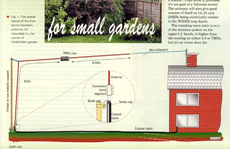 The Inverted L antenna is a versatile and efficient design suitable for small gardens, allowing amateur radio operators to operate on multiple bands. This project outlines the construction of a 5-band inverted L antenna, which can cover HF bands effectively. The design is particularly advantageous for those with limited space, as it requires minimal ground space while providing good performance. The antenna can be easily constructed using common materials, making it accessible for both beginners and experienced hams. In this guide, GM0ONX shares detailed instructions on how to build the inverted L antenna, including dimensions and tuning tips. The project emphasizes the importance of proper installation and grounding to ensure optimal performance. Additionally, it discusses the antenna's compatibility with various transceivers and the potential for portable operation. This resource is ideal for hams looking to enhance their station with a multiband antenna that performs well in limited space.
 -
 A 70 MHz Moxon rectangle antenna, built with 0.83mm enamelled copper wire and a lightweight fiberglass kite spar frame, offers a compact two-element beam solution for the 4-meter band. This design, originally for HF, scales effectively to VHF, reducing the antenna's width to approximately 75% of a half-wavelength while allowing direct coaxial cable feeding. The author, G6GVI, details the construction process, including the use of an automated design tool for precise dimensions. Initial field testing revealed a VSWR of approximately 1.3, with distinct nulls observed at 90 degrees when the antenna was mounted horizontally. The lightweight build, supported by a wooden block and U-bolt for mast attachment, makes it suitable for thinner mast sections. Further experimentation included testing with vertical polarization and considering its potential for indoor loft installation due to its relatively short major axis, offering a discreet option for urban hams.
 -
 Multi-band centre-fed antenna capable of very efficient operation on all HF bands, specifically designed with dimensions which allow it to be installed in gardens and other open spaces which accommodate a reasonably-straight run of 31.1m (102 ft) for the flat-top standard model.
 -
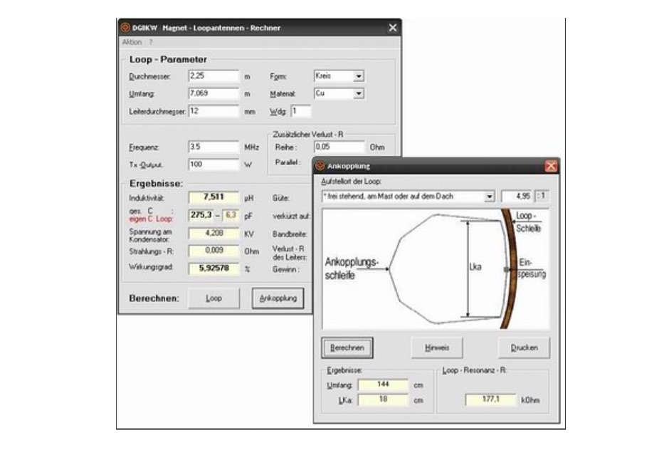 Magnetic loop antenna calculator and loop antenna design program for windows let you calculate dimensions for magnetic loops antennas, in german
 -
 A homemade antenna plan for a portable yagi beam antenna for the Six meters. Consist of a 3 elements yagi beam design include antenna dimensions, with elements lenght and spacing.
 -
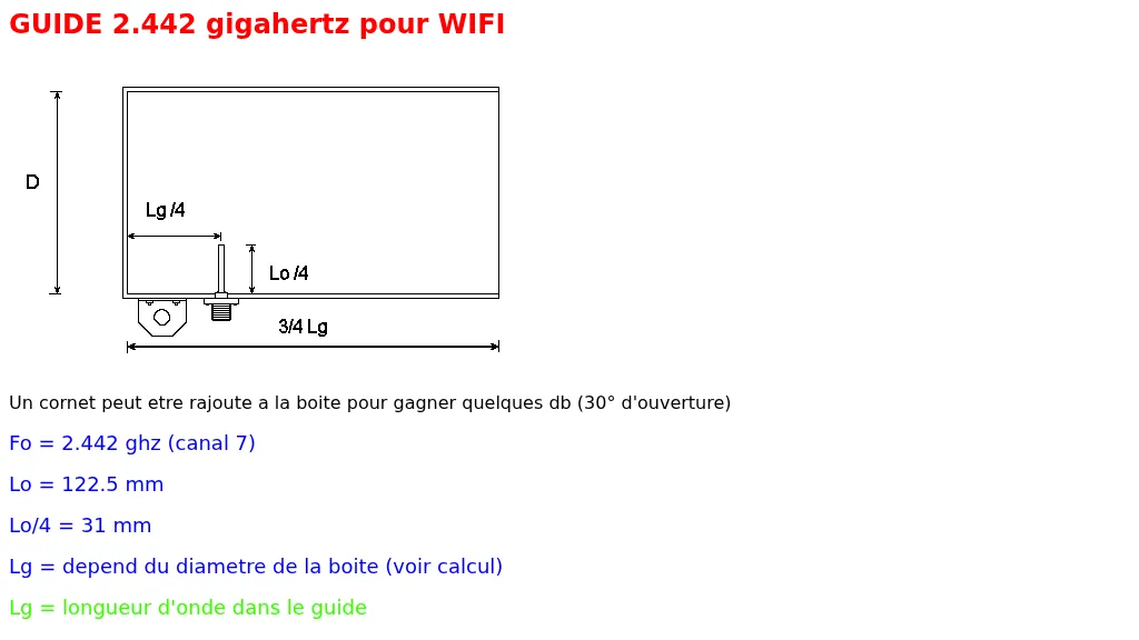 Demonstrates the construction of a 2.4 GHz horn antenna, specifically designed for WiFi applications, with the potential to add several dB of gain. The resource focuses on the critical dimensions and calculations required for proper operation, including _wavelength_ (Lo) and guide wavelength (Lg) based on the operating frequency (Fo) of 2.442 GHz, corresponding to channel 7. The guide provides a table of European WiFi frequencies, ranging from 2.412 GHz to 2.477 GHz, highlighting the specific channel 7 as the design target. It details how the length of the waveguide (Lg) depends on the diameter of the enclosure, offering a practical approach to antenna construction. This project outlines the necessary measurements like Lo/4 at **31 mm** and provides a link to an external calculator for further design specifics. The horn design aims for a 30-degree beamwidth, making it suitable for focused signal transmission or reception.
 -
 For amateur radio operators seeking a compact, directional antenna for the 10-meter band, this resource details the construction of a Moxon Yagi beam. The design utilizes readily available PVC pipe for the boom and elements, with specific measurements derived from the Moxon Rectangle Generator software. It outlines the assembly process for the main boom and end sections, providing critical dimensions for element spacing and overall length to achieve resonance at 28 MHz. The Moxon configuration offers a smaller footprint compared to a traditional Yagi, making it suitable for limited space installations. The article provides practical guidance for hams interested in a DIY antenna project, emphasizing the use of common hardware store materials. It specifies a 1 1/4" PVC schedule 40 pipe for the main boom and details the use of tees, reducing bushings, and 45-degree elbows for the element ends. Key measurements like the 55" spacing for the ends and the 150 3/4" overall length are provided, enabling replication of the design. The Moxon's inherent wide beamwidth and good front-to-back ratio make it an effective choice for DXing on 10 meters.
 -
 A **90-foot tall** top-loaded vertical antenna for the 160-meter band is detailed, constructed from aluminum irrigation tubing. The design incorporates four sets of four guy wires for structural stability, essential for an antenna of this physical size. This _monoband_ vertical is optimized for low-band operation, providing a robust solution for DXing and contesting on 1.8 MHz. The document includes specific construction methods for assembling the aluminum irrigation tubing sections and securing the guy wires. While a full NEC model is not explicitly provided, the physical dimensions and construction materials are sufficient for replication by experienced builders. The antenna's height and top-loading configuration are critical for achieving efficient radiation on 160 meters, particularly in minimizing ground losses.
 -
 The **NW3Z** optimized wideband antenna designs, originally presented at Dayton 2001, detail Yagi configurations for the 20-meter, 15-meter, and 10-meter amateur radio bands. This resource provides access to the design files, likely containing critical parameters such as element spacing, element lengths, and boom dimensions, which are essential for replicating these directional antennas. The designs focus on achieving wide bandwidth, a desirable characteristic for contesters and DXers operating across a significant portion of each band. The content specifically references "nw3z-Antenna-DesignsDownload," indicating that the core information is available as a downloadable file, presumably in a format suitable for antenna modeling software or direct construction. Such files typically include **NEC models** or similar data, allowing for performance analysis and optimization before physical construction. The emphasis on "optimized wideband" suggests design considerations for SWR bandwidth and gain characteristics over a broader frequency range than typical narrow-band Yagis. The resource serves as a direct source for specific, proven antenna designs from a known amateur radio antenna designer, offering practical data for hams interested in building high-performance Yagi arrays for HF.
 -
 Quagi antenna design, this little windows application let you calculate dimensions of elements and spacing of a quagi antenna. Freeware by VE3SQB
 -
 The K5OE 2-meter vertical mobile antenna design, detailed in this resource, employs a 3/8-wavelength vertical section complemented by four shortened radials, forming an off-center-fed vertical dipole. This configuration creates a self-contained lower half, enhancing efficiency compared to traditional 1/4-wave monopoles relying on vehicle bodies for a ground plane. The article specifies construction using PVC components, 10-gauge insulated wire for elements, and provides precise dimensions in both inches and centimeters for the 25-3/16" (64 cm) vertical and 7-3/16" (20 cm) radials. Performance data indicates an honest 3 dBi of gain at 6 feet elevation (2 dBi free-space), with a pattern favoring the horizon, suitable for Low Earth Orbit (LEO) satellite communications. At 20 feet high, the same antenna exhibits almost 6 dBi of gain, with a nominal 50 Ohm feedpoint impedance at 146.850 MHz. Tuning instructions involve trimming element lengths, with the author achieving a 1.2:1 SWR by pruning the mast to 24-3/4" and radials to 7". The resource highlights the antenna's effectiveness for mobile LEO satellite uplinks, particularly at low elevations, and its suitability for fixed, mobile, or portable operations. The flexible wire elements allow for easy folding, making it a practical choice for backpacking. The original design by K5OE was previously hosted on aol.com.
 -
 The ARRL ANTENNA Vol 5 COMPENDIUM features an article detailing two portable 6-meter antennas: a 2-element quad and a 3-element Yagi with telescoping elements. The 2-element quad exhibits a measured gain of **4.2 dB** over a dipole, while the 3-element Yagi achieves **5.8 dB** over a dipole. Both designs prioritize ease of construction and rapid assembly/disassembly for portable operations. Specific dimensions are provided for a 3-element 6-meter quad using #14 bare copper wire. The reflector element diameter is 6.2958 meters, the driven element 6.125 meters, and the director 5.8547 meters. Element spacing is 0.9398 meters between reflector and driven, and 1.1684 meters between driven and director. The SWR is under _1.26:1_ from 50 to 50.4 MHz, with a feed point impedance of 48.75 -j0.13 Ohms at 50.2 MHz, suitable for direct 50 Ohm coax feeding with a current _balun_.
 -
 Presents G0GSF Brian's ZS6BKW antenna, a refined iteration of the classic G5RV, offering improved performance across multiple HF bands. The design emphasizes specific radiator and ladder line lengths to achieve lower SWR on 40m, 20m, 17m, 12m, and 10m, making it a practical choice for operators seeking a single wire antenna solution. The document includes critical dimensions for the flat-top and the 450-ohm ladder line section, which are key to its multiband resonance characteristics. Unlike the original G5RV, the ZS6BKW aims for direct 50-ohm feedpoint impedance on several bands, reducing the need for an external antenna tuner. My field experience with similar optimized dipoles confirms that precise construction, particularly the ladder line length, is paramount for realizing the intended SWR benefits. This design offers a compelling alternative for hams with limited space or those preferring a less complex antenna system.
 -
 MoxGen is a **Windows** application designed to calculate dimensions and generate antenna model files for 50-ohm **Moxon Rectangle** antennas. Users input the desired design frequency in MHz and the wire size (AWG or diameter in inches/mm), and the software outputs the precise element lengths, spacing, and overall dimensions required for construction. It also creates a .maa file compatible with EZNEC, enabling further analysis and optimization of the antenna's performance characteristics. The software provides a visual representation of the Moxon rectangle, displaying key parameters such as gain, front-to-back ratio, and SWR at the design frequency. This allows radio amateurs to quickly assess the potential performance of their proposed antenna before physical construction. The generated EZNEC model facilitates detailed pattern analysis, impedance matching, and interaction with surrounding structures, proving useful for both initial design and fine-tuning.
 -
 The BV6 50 MHz Yagis resource details the construction of two distinct Yagi antenna designs for the 6-meter band, specifically a 1-wavelength (1wl) model and a 2.1-wavelength (2.1wl) model. The 1wl Yagi, with a boom length of 5.850m, achieves a gain of **9.4 dBd**, while the 2.1wl Yagi, spanning 12.90m, boasts a gain of **11.9 dBd**. These designs adhere to a proven methodology for optimizing current slope and maintaining constant phase delay across parasitic elements, ensuring high gain per boom length and an _excellent pattern_. Both designs target a 50-ohm input impedance, facilitating straightforward feeding with a robust folded dipole. Final verification using NEC-II software confirmed the antennas' exceptional stacking capabilities, yielding stacking gains exceeding **5.8 dB** for a 2x2 array with minimal mutual detuning. The resource provides common mechanical data, including boom and element diameters, and specifies element lengths corrected for boom diameter. While the original _DUBUS Technik V_ publication contained incorrect element lengths, this resource provides the accurate dimensions for proper construction, emphasizing the use of readily available materials for cost-effective amateur radio deployment.
 -
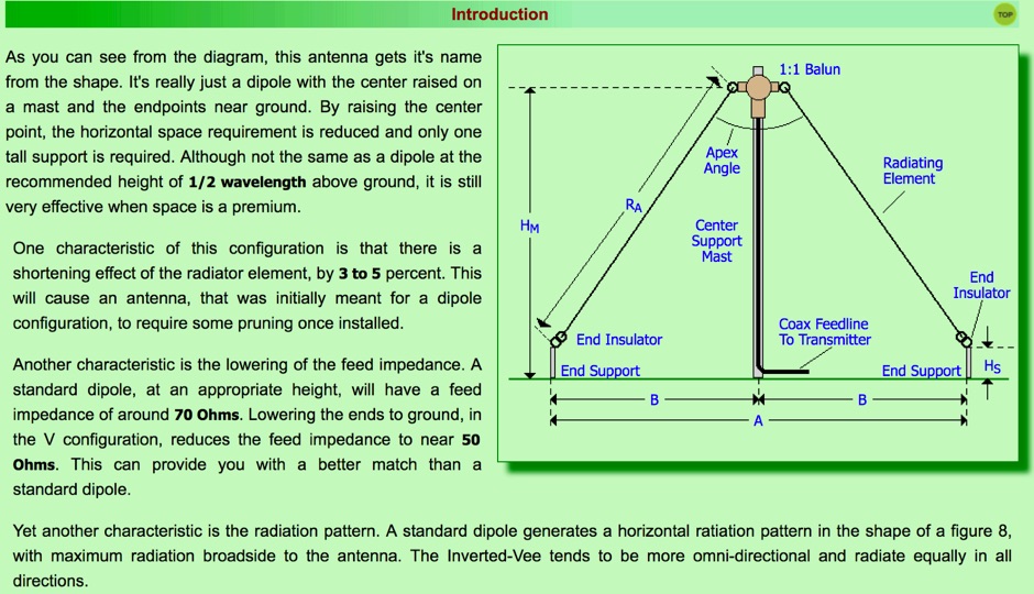 Inverted V antennas is a dipole with the center raised on a mast and the endpoints near ground. Calculate dimensions online.
 -
 The "Largest YU Moxon" document meticulously details the design and construction of a substantial multiband Moxon antenna, primarily for 80m, 40m, and 20m operation. It presents specific design parameters derived from NEC-based simulations, including a 4-element 80m Moxon with 37 dB F/B and 7.81 dBi gain on a 47m boom, a 4-element 40m Moxon with a bidirectional pattern, and a 6-element 20m Moxon optimized for specific side lobes. The resource provides precise element lengths and spacing in meters for each band, alongside measured SWR results across the 3.650-3.800 MHz, 7.000-7.100 MHz, and 14.000-14.350 MHz segments. The construction narrative outlines the challenges and solutions encountered by the YU team, including the use of trees for support, the creation of "ugly" air-choke baluns from RG-58 cable wound on plastic bottles for each band, and the meticulous process of attaching wires to a rope boom. It documents the physical dimensions of the vineyard site (47 x 38m) and the azimuth orientation (340 degrees) chosen for the antenna. The document is distinctively useful for its practical insights into large-scale antenna deployment in a field environment, offering real-world SWR measurements and anecdotal performance reports from CQWW contest operations. It includes numerous photographs illustrating the construction process, the team members, and the finished antenna structure, providing visual context to the technical details.
 -
 Designing a compact directional antenna for the 70cm band involves balancing gain, front-to-back ratio, and physical size. This resource details the construction of a 2-element Moxon rectangle antenna for 432 MHz, outlining the specific dimensions for the driven element and reflector, and discussing the advantages of its folded dipole configuration. The article provides insights into the historical context of 70cm operations and the author's personal experiences with early 432 MHz transceivers and antenna setups, such as a Jaybeam 48-element TV antenna. It also touches upon the practical aspects of building and deploying such an antenna for local and weak-signal work. The Moxon antenna design is compared to a 3-element Yagi, noting its superior front-to-back ratio and broader bandwidth for a given boom length, making it suitable for portable operations or restricted spaces. The construction uses readily available materials like copper wire and PVC tubing, emphasizing simplicity and ease of replication. Performance characteristics, including a reported gain of approximately 5.5 dBi and a front-to-back ratio of 20 dB, are discussed in the context of its compact footprint. The resource includes a visual representation of the antenna's dimensions and construction, aiding in practical implementation.
 -
 This technical note explores the application of **Moxon rectangle** antennas for WARC bands, specifically 17 and 12 meters, as compact directional alternatives to standard Yagis. It details three design approaches: a dual-band Moxon using open-sleeve coupling, a Moxon-Yagi combination, and a simplified 1.5 Moxon rectangle. The document provides specific dimensions in feet for aluminum tubing elements (0.75" and 0.5" diameter) for each configuration, along with projected free-space gain, front-to-back ratio, and feedpoint impedance (R+/-jX Ohms) across the respective band segments. Performance tables illustrate gain (dBi), front-to-back ratio (dB), and 50-Ohm VSWR for each design. The dual-band Moxon, despite its compact 7-foot boom, is not recommended due to extreme sensitivity to construction variations, leading to rapidly changing performance characteristics. The Moxon-Yagi combination, featuring a 17-meter Moxon and a 12-meter director-driver Yagi, is presented as a more practical and adjustable solution, offering stable performance with a 10-foot boom. NEC model descriptions are included for simulation in programs like EZNEC, NEC-Win Plus, AO, or NEC4WIN.
 -
 Calculates precise dimensions for **Moxon rectangle** HF antennas, enabling hams to design antennas by inputting desired resonant frequency and wire diameter. This web-based tool, version 0.5, is a PHP front-end developed by W4/VP9KF, based on a public domain BASIC program originally authored by L. B. Cebik, W4RNL. It generates critical measurements for the driven element and reflector, ensuring proper spacing and element lengths for optimal performance. User feedback confirms the calculator's accuracy, with one user reporting resonance within 50 Hz of the design frequency for an 18 MHz antenna, eliminating the need for SWR adjustments. This contrasts with other online tools that resulted in significant frequency discrepancies. The tool's precision facilitates building **directional antennas** for specific bands, contributing to effective DXing and contesting operations.
 -
 In 1999, W5GVE presented a detailed construction article for a 2-meter _DDRR_ antenna, specifically designed for mobile operation. This unique antenna, a Directional Discontinuity Ring Radiator, offers a compact footprint, making it suitable for vehicular mounting where traditional quarter-wave verticals might be impractical. The design emphasizes ease of homebrewing, utilizing readily available materials and basic workshop tools, allowing radio amateurs to build an effective mobile antenna for the 144 MHz band. The article provides insights into the antenna's performance characteristics, noting its low profile and potential for reduced wind loading compared to taller mobile whips. W5GVE's experience with the DDRR design suggests it can provide reliable communications on the 2-meter band, even in challenging mobile environments. The construction details include specific dimensions and assembly steps, guiding the builder through the process of creating a functional antenna. This project offers a practical alternative for hams seeking a discreet yet effective 2-meter mobile antenna, potentially achieving **3 dB** gain over a standard mobile whip.
 -
 The document details the optimization and construction of the _Maria Maluca_ antenna, a compact 6-band (20m-6m) directional beam. It presents a comparative analysis of shortwave antenna principles, highlighting the efficiency gains achieved by using an open feeder line and tuner as a resonant unit, contrasting this with the losses associated with traps or capacitive loads in multiband antennas. The resource specifically revisits an older South American 2-element design for 10, 15, and 20 meters, applying modern NEC-based software to develop a six-band version. Performance data is meticulously tabulated, showing impedance, free space gain, gain at 12m height, elevation angle, and front-to-back (F/B) ratio for each band from 20m through 6m. For instance, on 15m, the antenna achieves 5.1 dBd free space gain and 13.72 dB F/B ratio. The construction section provides practical guidance on element assembly using aluminum pipes and hose clamps, detailing the use of a heavy-duty glass fiber reinforced polyamide rod for electrical separation and bending strength. It also specifies the use of 450-ohm _Wireman_ line CQ 552 for the transmission line. The document includes diagrams for rod fixing, an air-wound balun, and a vertical elevation diagram for the 15m band, illustrating its DX qualification. It also discusses the antenna's suitability for portable and expedition operations, noting its compact transport dimensions (max 1.50m length, 12 lb weight) and quick assembly time (under 15 minutes). The author, Dipl.Ing. Helmut Oeller, DC6NY, is identified as a source for material kits.
 -
 W1ZY's 40-meter **Moxon** antenna project details nine months of experimentation, culminating in a reversible array built from No. 12 insulated wire. The design incorporates two RF current baluns and a unique two-wire element construction, where each element consists of two parallel wires spaced 3 inches apart. The resource provides specific dimensions for the first prototype, including A=50.98', B=7.87', C=1.25', D=9.3', and E=18.42', optimized for 7.050 MHz CW operation. It thoroughly explains the construction of custom two-wire insulators from Plexiglas semi-rods and the critical pre-tensioning process required to maintain wire separation and array integrity. The author, Bill, emphasizes the antenna's exceptional receive performance, noting a 30-35 dB front-to-back ratio, which allows for significant signal rejection from the rear. While the Moxon offers 5-6 dB gain on transmit, its primary advantage lies in its ability to radically reduce rear-facing signals on receive, a characteristic Bill believes is often overlooked in transmit-focused comparisons. The guide details a flexible tuning method using removable tail-end jumpers, enabling adjustments to both tail-end and parallel dimensions without re-soldering the feed point, a technique refined over three prototypes.
 -
 Constructing a compact UHF Moxon antenna for portable radio or TV applications demands a small, easily transportable aerial. This project focuses on a straightforward build method rather than a specific frequency design, leveraging _MoxGen_ software by AC6LA to derive precise dimensions. The author's approach utilizes an epoxy printed circuit board as the support, with traces drawn by a special felt-tip pen for soldering the antenna elements after an etching bath. For high-frequency work, particularly in the GHz range, the choice of insulating material is critical; the article emphasizes the necessity of quality UHF or SHF-grade insulation. A standard SMA connector is integrated, with one element making electrical contact via the nut and the other soldered to the central pin. This ensures a robust feedpoint for the coaxial cable. The coaxial cable, fitted with its connector, is threaded through a 12mm PVC tube that functions as a mini-mast. This tube also defines the antenna's forward direction, which should be aimed at the target signal. A sanitary clamp at the base of the tube secures it to a photographic tripod via its 7mm thread, providing a stable and portable mounting solution.
 -
 Constructing a Lindenblad antenna for 137MHz NOAA satellite reception involves specific design considerations for optimal performance. The resource details the use of 4mm galvanised steel fencing wire, 300-ohm television ribbon cable, and wood/plastic components for the antenna structure. Key dimensions for a 137.58MHz-resonant antenna are provided, derived from the ARRL Satellite Handbook, specifying s, l, w, and d as 42, 926, 893, and 654mm respectively. The antenna is designed for Right Hand Circularly Polarised (RHCP) signals, requiring the four folded dipole elements to be tilted clockwise by 30 degrees. A significant aspect covered is impedance matching between the antenna's 75-ohm impedance and a typical 50-ohm receiver input. A twelfth-wave matching transformer, constructed from 117mm sections of 50-ohm RG-58 and 75-ohm RG-59 coax with a 0.66 velocity factor, is described. The article also addresses coaxial cable and connector selection, recommending 75-ohm Type-N connectors for RG-6 cable in professional setups and F56/F59 connectors for general use, while strongly advising against PL-259/SO-259 connectors for VHF. Strategies for mitigating Radio Frequency Interference (RFI) are discussed, including antenna placement to shield from local TV transmitters and the use of commercial or DIY band-pass filters, such as cavity resonators or helical notch filters, along with ferrite chokes on coaxial cables. Antenna orientation is explored, noting the Lindenblad's 'cone of silence' directly overhead and its maximized sensitivity towards the horizon. An experimental vertical tilt of 90 degrees is presented as a method to improve overhead reception and reduce interference from strong horizontal signals, particularly relevant in high RFI environments like the Siding Spring Observatory site.
 -
 A 7 MHz vertical half-Moxon array, designed by F6IRF, is presented with its MMANA model, featuring a 20cm gap between the two horizontal elements. The design aims for a low take-off angle, crucial for DX work, and includes specific dimensions for the driven element and reflector, which are constructed from 2mm copper wire. The antenna's feedpoint impedance is approximately 50 ohms, allowing for direct coax feed without a matching network, and it is intended for portable or temporary installations. Field results indicate the antenna provides a **3 dB** gain over a quarter-wave vertical, with a front-to-back ratio of **10 dB** on 40 meters. The author notes successful DX contacts into _VK_ and _ZL_ from France, demonstrating its effectiveness for long-haul communication. The design emphasizes simplicity and portability, making it suitable for operators seeking a directional antenna solution for the 40m band without complex setup requirements.
 -
 Illustrates the construction of a compact _Moxon_ beam antenna specifically tailored for the 40-meter band (7 MHz). The resource details a homebrew project by W7XA, emphasizing its design for limited space while maintaining good bandwidth and directivity characteristics. It highlights the practical application of the _Moxon_ rectangle model to achieve performance on a lower HF band. The primary content is a downloadable PDF document titled "40-Meter-Mini-MOXON-Beam-Antenna.pdf," which provides comprehensive illustrations and technical specifications for replicating the antenna. This includes dimensions, materials, and assembly instructions, making it a practical guide for radio amateurs interested in directional antennas for HF. The project demonstrates how a relatively small footprint can yield a directional antenna suitable for DXing or contesting on 40 meters, a band typically requiring much larger arrays for similar gain and front-to-back ratios. The documentation supports hands-on construction.
 -
 This project outlines the construction of a 3-element reversible quad antenna specifically designed for the 40-meter band. The materials required include pushup towers, pressure-treated posts, insulated wire, and various electrical components such as relays and a balun. The construction process is straightforward, beginning with the installation of the posts in a straight line, followed by the assembly of the antenna elements and their elevation to the desired height. The antenna's design allows for directional signal reception, making it ideal for operators looking to enhance their communication capabilities on the 40-meter band. The project includes detailed instructions on tuning the antenna for optimal performance, ensuring that operators can achieve the lowest SWR possible. Additionally, the design can be adapted for other bands by extrapolating dimensions, providing versatility for amateur radio enthusiasts. Overall, this reversible quad antenna project is suitable for both beginners and experienced operators, offering a practical solution for improving signal strength and directionality in 40-meter communications.
 -
 A 20-meter Moxon antenna design provides a compact directional solution for the 14 MHz band, achieving approximately **5.5 dBi** of forward gain and a front-to-back ratio exceeding 20 dB. This rectangular wire array, consisting of a driven element and a reflector, offers a smaller footprint than a traditional 2-element Yagi, making it suitable for space-constrained installations. Construction details focus on specific dimensions for the wire elements, fed with 50-ohm coaxial cable. The _Moxon rectangle_ inherently delivers wide bandwidth and a clean radiation pattern, simplifying tuning with a relatively low SWR across the entire 20-meter band. Its robust performance makes it a practical choice for both fixed stations with limited tower space and portable _DXing_ operations. The design's characteristics are particularly beneficial for contesting and long-haul communications on 20 meters.