Search results
Query: full wave antenna
Links: 73 | Categories: 1
Categories
-
 The antenna is a 10 - 160 meter horizontal loop fed with 450 ohm ladder line all the way into the ham shack to an Palstar AT1500BAL balanced line antenna tuner
 -
 This resource provides a detailed guide on constructing a J-pole antenna specifically for the 2 meter band, which is popular among amateur radio operators. The article outlines the materials needed, including various sizes of aluminum pipes and PVC, as well as the tools required for assembly. It emphasizes the simplicity and effectiveness of the J-pole design, making it an ideal choice for newcomers to amateur radio. The instructions are straightforward, allowing users to build the antenna in less than an hour, and include tips for tuning the antenna for optimal performance. In addition to the construction details, the resource includes practical advice on the assembly process, such as how to cut and join the pipes, as well as how to mount the SO239 connector. The author shares personal experiences and insights on achieving a low standing wave ratio (S.W.R.) and suggests modifications for creating bi-band or tri-band J-pole antennas. This comprehensive guide is enriched with photographs that illustrate the construction steps, making it easier for users to follow along and successfully build their own J-pole antenna.
 -
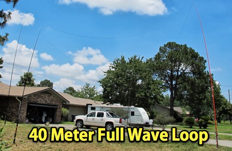
 How to make the Super antenna. To build this antenna you need a lot that is at least 100 feet across. Antenna covers all bands 80-10 meters + 30, 17, 12 meter WARC Bands This antenna works as a Full Wave Loop on 80 Meters and also works as a 2 wavelength open loop or Bi-Square on the 40 Meter band
 -
 Constructing a 2-meter 5/4 wave antenna, N1HFX details a design fully enclosed within 3/4-inch PVC tubing, addressing the significant velocity factor of PVC which necessitates a 19% reduction in physical length. The design incorporates a specific matching system using 300-ohm TV twin lead to counteract the highly inductive impedance component inherent in a 5/4 wave radiator. Key components include #18 stranded insulated wire for the radiating element, RG58/U coax, a PL259 connector, and a hardwood dowel for internal support, all carefully dimensioned for optimal performance within the PVC housing. The article provides precise cutting lengths for the twin lead and #18 wire, with the overall assembly measuring 77 3/4 inches, reflecting an approximate velocity factor of 0.81. Tuning instructions emphasize taking SWR readings with the antenna assembly inside the PVC, adjusting the #18 wire and twin lead in small increments to achieve a low SWR across the 2-meter band. The prototype antenna achieved SWR readings below 1.2:1 across the entire band, and N1HFX suggests an estimated 6 dB gain when properly mounted, offering a cost-effective alternative to commercial antennas.
 -
 The boomless quad antenna is a unique design that offers versatility for amateur radio operators. This antenna consists of two half-wave dipoles arranged in a square or circular shape, allowing for both vertical and horizontal polarization depending on the feed point. The design facilitates easy installation and rotation, making it suitable for various operating conditions. The construction utilizes strong materials, such as bamboo, and incorporates waterproofing techniques to enhance durability. This project outlines the necessary dimensions and materials, including copper wire and insulators, to successfully build the antenna. It emphasizes the importance of tuning each radiator element for optimal performance. The boomless quad is particularly effective across multiple HF bands, including 14 MHz, 21 MHz, and 28 MHz. By following the detailed instructions, operators can achieve a reliable and efficient antenna setup that enhances their DXing and contesting capabilities.
 -
 A dual loop antenna, ZZ Wave Net HF Wire Antenna Project by VE6VIS. The antenna is basically a full wave 80 meter loop on top and a 40 meter loop on the bottom all supported from a 64 foot center support
 -
 Determining the actual need for an antenna tuner often hinges on the specific antenna and feed line configuration in use. While many hams believe a tuner is always essential, its primary role is to present a 50-ohm impedance to the transceiver, not to "tune" the antenna itself. For instance, a resonant dipole fed with _coaxial cable_ at its design frequency typically requires no tuner, as the feed line impedance closely matches the radio's output. However, operating a non-resonant antenna, or using a resonant antenna on multiple bands, frequently necessitates a tuner to manage high Standing Wave Ratio (SWR) on the feed line. The article clarifies that a tuner placed at the transceiver only matches the radio to the feed line, not the antenna to the feed line. For maximum efficiency with a non-resonant antenna, an _automatic antenna tuner_ (ATU) or a remote tuner placed at the antenna feed point is often more effective, minimizing losses in the feed line. The discussion also touches on the practical implications of SWR, noting that modern transceivers often fold back power at high SWR, making a tuner a practical necessity to achieve full output power, even if the antenna itself is not perfectly matched.
 -
 Details the construction and optimization of antenna systems for amateur radio satellite operations, focusing on practical, homebrew solutions for VHF/UHF bands. It covers building _groundplane antennas_ from salvaged materials, recycling old beam antennas into new configurations like a 2-meter crossed yagi, and constructing a 10-meter horizontal delta loop. The resource also explains antenna matching techniques, including folded dipole driven elements and quarter-wave transformers, along with the importance of accurate SWR measurements and minimizing coax loss. Demonstrates how to achieve a **1:1 SWR** by carefully trimming elements and adjusting radial angles on groundplane antennas. It provides insights into selecting appropriate coax and connectors, highlighting the benefits of Belden 9913 for low loss and the proper installation of _N-connectors_. The article also addresses RFI mitigation from computer birdies and presents a design for a silent triac antenna control circuit, offering practical solutions for common satellite station challenges.
 -
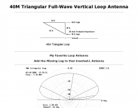 A 40 meters band full wave antenna project plan with model, adding the Missing Leg to the Inverted-L Antenna
 -
 This Delta Loop is a three-sided antenna suspended high in the air by vertical supports, such as tall evergreen trees. Recommended height is 40 feet or more at highest point, but higher is better.
 -
 ZZ Wave Net is a 40 & 80 meter full wave loop designed to fit on a city lot. ZZ Antenna is a folded dipole bent into an inverted V loop
 -
 Demonstrates the construction and on-air performance of the _NB6Zep_ antenna, a modified 20-meter Extended Double Zepp design optimized for multi-band operation from 40 through 10 meters. The resource covers basic design principles, including dimensions of 66 feet horizontal and 5 feet vertical elements, and specifies open ladder line or TV twin lead for the transmission line. It details material selection for low-cost wire antenna construction, such as 18 AWG wire for the legs and ceramic or plastic insulators, along with practical tips for soldering connections and insulating against moisture. The author, NB6Z, shares insights from extensive _EZNEC_ modeling to optimize the antenna's total length for a 40-meter half-wave dipole footprint and feed line length for direct tuner connection. The article presents field results, including successful _PSK31_ contacts from Oregon to the East Coast on 40 and 30 meters with 50 watts, even at a low height of 6 feet. It provides detailed performance characteristics for each band, noting the _NB6Zep_'s highest gain (over 3 dB) and sharp, medium-angle lobes on 20 meters, which yielded strong DX reports to locations like Korea, Japan, and Argentina. For 17 and 15 meters, it describes a butterfly-like pattern with broad lobes, while 12 and 10 meters exhibit narrow, directional lobes in an "X" configuration. The author also shares personal experiences operating successfully for over a decade in an antenna-restricted environment using the NB6Zep and other stealth wire antennas.
 -
 The cobweb antenna it is basically a 5 band antenna comprising of 5 full half wave dipoles for each band - between 10 meters and 20 meters, the antenna is also resonant on 6M and can be modeled even for VHF frequencies.
 -
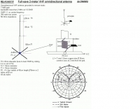 A full wave 2-meter VHF omnidirectional antenna by ON6MU
 -
-
 An horizontal full wave wire loop antenna for the 80 meters band by W4HM
 -
 These omnidirectional antennas offer Horizontal polarization, and about 2.1 dbd of gain. They are much quieter than a dipole or a vertical, have a broader bandwidth and will usually out perform a dipole antenna.
 -
 A 40-meter reversible _Moxon rectangle_ antenna project details its construction and performance, featuring 51-foot long sides and 7.7-foot turned-in sections. The design incorporates a 16.5-foot boom, with elements spaced 1.1 feet apart, constructed from #14 covered wire. It utilizes two double-pole relays for switching between NE and SW directions, achieving F/B ratios up to 40 dB on CW and 30 dB on SSB, with distinct reflector stub settings for each mode. This antenna replaced a full-size 2-element Yagi, demonstrating comparable forward gain while offering superior F/B ratios and directional flexibility. _EZNEC_ modeling indicates only 0.2 dB less forward gain than the Yagi. The system uses no baluns, relying on half-wave feedlines and switched stubs for impedance matching. The antenna is tree-supported at 45 feet, with its effective radiation height modeled at 80 feet due to local terrain, enhancing its performance over a nearby lake.
 -
 VE3HCR article of a home made loop antenna for 80 meters band
 -
 Also known as W0MHS Loop Skywire or Full Wave Loop Antenna, here you can find N1SU interesting observations on this antennas.
 -
 This high antenna require a large ground composed by 40 radials. It's not very handy expecially in windy situations but is very powerfull in pile-ups. In italian
 -
 21 mhz half wave ant -very low radiation angle - full size and light weight- all coax matching system - decoupling care to prevent low angle radiation degrade
 -
 Design your owm HF shiortened dipole. Includes a diagram of a lumped-constant loaded dipole antenna that is intended to fit in available space, rather than requiring a full 1/2 wavelength, at a specified frequency
 -
 JJ0DRC's HF multi-band delta loop antenna project, initially conceived during the waning peak of Cycle 23, addresses the common challenge of achieving effective DX operation from a small residential lot in Japan. Dissatisfied with a ground plane antenna's performance in SSB pile-ups, the author sought a beam-like solution without a tower, drawing inspiration from a JJ1VKL article in CQ Ham Radio Sep. 2000. The antenna, constructed in October 2000, employs two 7.2-meter fishing rods (37% carbon fiber, reinforced with cyano-acrylate glue and aluminum tape) and 1mm enameled wire, fed by an Icom AH-4 external antenna tuner. While the exact beam pattern remains unmeasured, JJ0DRC observed a significantly higher callback rate compared to dipole antennas, particularly on higher bands. The system's circumference length of 15-20m is crucial for maintaining a good beam pattern across HF bands, though performance on lower bands like 80m, 40m, and 30m becomes less directional as the length deviates from a full wavelength. Ongoing maintenance addressed degradation issues, including aluminum tape cracking and wire breakage at connection points due to strong winds (often exceeding 10-15m/s in winter). The author reinforced rod connections with IRECTOR PIPE SYSTEM components and INSU-ROCK ties, and improved wire attachment methods using Cremona rope and epoxy bond to enhance durability.
 -
 This article describes how to use a phone line as a shortwave receiving antenna, but be carefull telephone lines present a potential shock hazard, use at your own risk
 -
 This is a 200 Watt PEP step up transformer for end fed full and half wave antennas without radials, designed as a 200 Watt PEP
 -
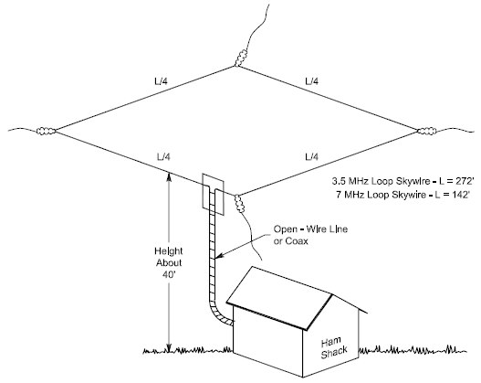
 A 7MHz Full wave loop antenna in diamond shape for field day operations made with three 31 foot Jackite poles
 -

-
 Ham radio antennas and electronics, specialized in 1/2 wave dipole, OCF dipole, windom, full wave loop, end fed, inverted L, portable end fed antenna, long wire, SWL antenna, fan dipole, multiband dipole, G5RV and military antennas.
 -
 Article using a full wave delta loop antenna at low height, feeding methods, performance reports on 1984 QST article by W1FB and W1SE
 -
 The G5RV multiband HF antenna, designed by Louis Varney (G5RV) in 1946, is a popular compromise antenna offering good overall performance on most HF bands when paired with an external antenna tuner. The basic full-size G5RV measures 102 feet across the top for 80 through 10 meter operation and is fed at the center via a 34-foot low-loss feed-stub. This interaction between the radiating section and the feed-stub facilitates matching across 80-10 meters with a standard tuner, often eliminating the need for ladder line directly to the shack. The antenna's design center frequency is 14.150 MHz, configured as a 3/2-wave dipole on 20 meters, with its 102-foot length derived from long-wire antenna formulas. Construction details emphasize the matching section, which can be open wire, ladder line (window-type), or TV twin lead. Each type has a specific velocity factor (VF) affecting its physical length for an electrical half-wave on 14 MHz; for instance, open wire requires 33.7 feet (VF 0.97), ladder line 31.3 feet (VF 0.90), and TV twin lead 28.5 feet (VF 0.82). The article provides formulas for calculating these lengths and discusses the antenna's behavior on individual bands, from 3.5 MHz where it acts as a shortened dipole, to 28 MHz where it functions as two three-half-wave long-wire antennas fed in-phase. Practical construction notes include recommendations for vertical descent of the matching section, sealing the coax junction, providing strain relief, and winding a coaxial choke coil to mitigate common mode current. The resource also presents dimensions for double-size (204 ft) and half-size (51 ft) G5RV versions, along with their corresponding matching section lengths for various line types, making it a versatile reference for hams considering this classic wire antenna.
 -
 Although a magnetic loop antenna(aka small loop antenna) is very compact, its efficiency is close to a half-wavelength dipole if carefully built.
 -
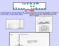
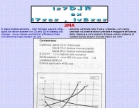 3 band mobile antenna - 10m full size wave/4 whip - quick tilt-down system for 20 and 15 m loading coil change by IZ7DJR
 -
 A simple and awesome wire monoband antenna, very usefull for portable and dxpeditions usage, consist of two elements, a driver and the reflector. This endfed halfwave gives a very low take off angle and is very suited for chasing DX.
 -
 The ZS6BKW multiband antenna, an optimized variant of the classic G5RV, features a 102-foot (31.1 m) horizontal span and a 39.1-foot ladder line matching section. This design, derived by G0GSF (formerly ZS6BKW) in the early 1980s using computer programs and _Smith charts_, aims for improved SWR across multiple HF bands compared to its predecessor. Construction details specify Wireman 554 ladder line and #14 AWG THHN copper wire for the radiators, with precise instructions for determining the velocity factor (VF) of the ladder line using an antenna analyzer or dip meter, ensuring accurate physical length for the matching section. The radiator length is electrically 1.35 wavelengths for the 20-meter band, requiring careful trimming during tuning. Field measurements with an _AIM-4170C_ analyzer by KI4PMI and NC4FB demonstrated good SWR curves and bandwidth on 6, 10, 12, 17, 20, and 40 meters. The antenna was deemed unusable on 15 and 30 meters due to very high SWR, but an LDG AT-100PRO autotuner successfully brought 6 and 80 meters into tune. Contacts were made on 80, 40, 20, and 17 meters, including a **17-meter** contact to Spain. EZNEC models for 80-6 meters are provided, along with an AutoEZ model by AC6LA, which predicted good SWR for 80-10 meters. W5DXP's modifications for an all-band HF ZS6BKW are also referenced.
 -
 This project details the construction of a **full-sized 40-meter vertical antenna**, born from a renewed interest in 7 MHz operation and a desire for improved effectiveness over simple dipoles. The author, K5DKZ, initially focused on VHF experimentation, which provided an inventory of aluminum tubing and fiberglass spreaders for this endeavor. Before this vertical, K5DKZ utilized an 80/40 meter inverted-vee trap dipole and a 40-meter broadband dipole, but now primarily uses a pair of full-sized, phased, quarter-wave verticals spaced 35 feet apart for serious 40-meter work. The construction involves a base-heavy design for stability, using a 44.5-inch section of 1-1/4 inch steel TV mast driven into 1-3/8 inch aluminum tubing, insulated by a 105-inch section of Schedule 40 PVC pipe. The assembly reaches 31 feet, close to the 32 feet required for a quarter-wavelength on 40 meters, with fine-tuning achieved by winding wire onto a fiberglass spreader. The design is explicitly presented as a foundation for a two-element 40-meter Yagi beam, outlining modifications like substituting aluminum for steel in the base and using an inductive hairpin match for the driven element. The article also discusses tuning considerations for a large 40-meter beam, noting the 100 to 200 kHz upward frequency shift when raised, and suggesting methods for installation on a tower. The author emphasizes the cost-effectiveness and good performance of the monopole approach, especially when multiple verticals are needed.
 -
-
 This PDF document details the construction of a **70 MHz** Big Wheel antenna, a horizontally polarized omnidirectional array. The design utilizes three full-wave loops, each approximately **2160 mm** in diameter, arranged in a triangular configuration. The resource provides mechanical dimensions for the antenna elements and a comprehensive bill of materials, specifying component quantities and types, such as M8 stainless steel bolts, 15x15x1.5 mm square aluminum tubing for spacers, and 8 mm aluminum rod for the arcs. The central hub is constructed from two 160x160x8 mm aluminum plates, with four 40 mm long polyamide insulators supporting the radiating elements. The feed system incorporates a 50 mm diameter aluminum pipe for mounting and a matching stub constructed from a 120x20x2 mm aluminum sheet, connected via M8x10 mm bolts. The resource includes a diagram illustrating the mechanical dimensions and assembly points, including the N-connector fixing point and the center conductor attachment. The project was published on May 25, 2011, by Peter OE5MPL and Rudi OE5VRL. DXZone Focus: PDF | 70 MHz Big Wheel | Mechanical Dimensions | **2160 mm** loop diameter
 -
 The X80 multi-band HF vertical antenna, a commercial iteration of the Rybakov design, exhibits a physical length of 5.5 meters, or approximately 18 feet, and is constructed from aluminum tubing. It operates as a non-resonant vertical, requiring an external antenna tuner for impedance matching across its intended operating frequencies. The antenna's design incorporates a 1:4 UNUN at its base, facilitating a nominal 50-ohm feed point impedance for the coaxial cable. Performance observations indicate effective operation on 40 meters, 20 meters, 15 meters, and 10 meters, with reduced efficiency on 80 meters and 160 meters due to its relatively short electrical length for these lower bands. Comparative analysis with a G5RV dipole and a half-wave end-fed antenna reveals the X80 offers a lower take-off angle, beneficial for DX contacts, particularly on the higher HF bands. Field tests conducted with an Icom IC-706MKIIG transceiver and an LDG AT-100ProII autotuner demonstrate the X80's ability to achieve acceptable SWR across 80m through 10m. The antenna's compact footprint and ease of deployment make it suitable for restricted spaces or portable operations, though its performance on 80 meters is noted as a compromise compared to full-size resonant antennas.
 -
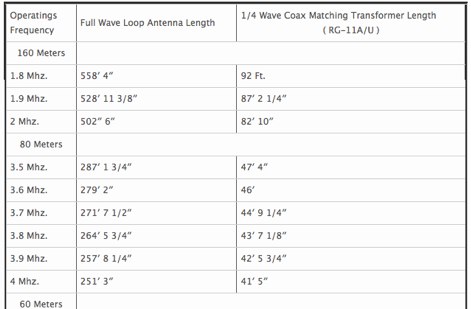
 Use this online calculator to determine the length of a full-wave loop antenna from the frequency. Both metric and English units of measurement are supported. Quarter-wave matching section lengths are also calculated.
 -
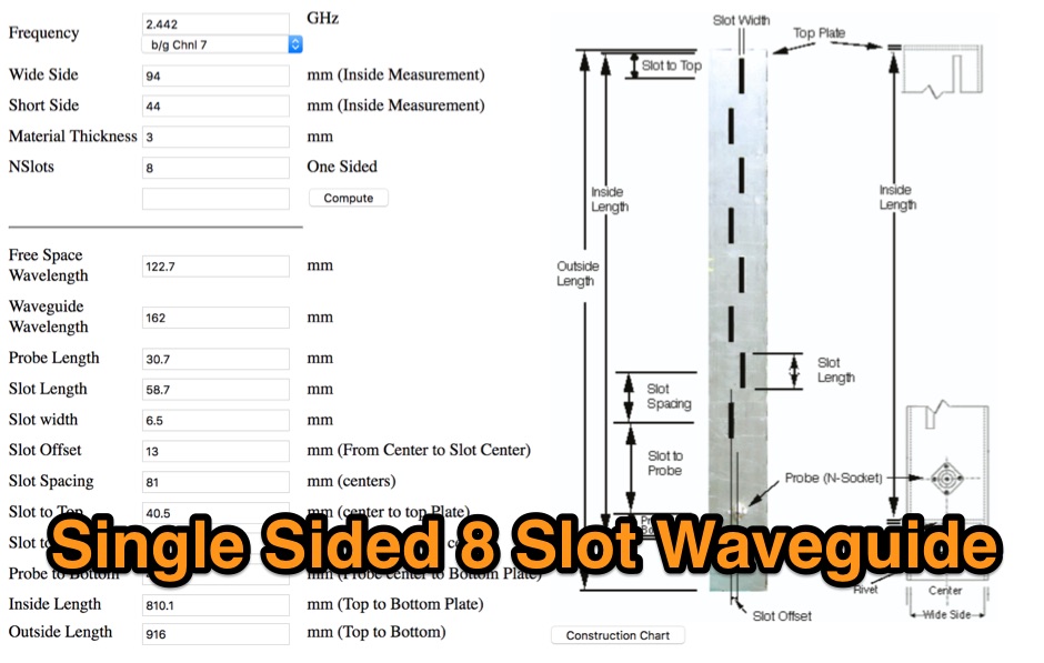 Online calculator and a full documented pictorial guide to build a single sided 8 slot waveguide antenna
 -
 Dipole, inverted V, full wave loop and grond plane antenna quick reference plans
 -
 The NB6Zep Antenna, an electrically shortened 80-meter end-fed wire, addresses space constraints for low-band operation by integrating two loading coils into a 37-foot wire. This design, modeled with _EZNEC_, explores configurations like the quarter-wave sloper and inverted-L, with the latter providing a more vertical radiation pattern and practical backyard deployment. The resource details specific coil construction, recommending 21 uH coils made from _BW coil stock #3026_ or similar, and outlines wire segment lengths for optimal tuning. Performance analysis indicates a radiating efficiency of approximately 27% with good ground conductivity, resulting in a signal typically 3-4 dB down compared to a full-size quarter-wave vertical. The antenna exhibits a narrow bandwidth, around 50 kHz, due to its high Q, necessitating a tuner for broader band operation. Feedpoint impedance is low, with ground resistance playing a critical role in achieving a usable SWR. The article emphasizes the importance of an effective ground rod at the feedpoint for proper operation and tuning, suggesting an antenna analyzer for precise adjustments. It confirms the antenna's suitability for DX, citing successful contacts from Oregon to the East Coast and Hawaii on a 160-meter variant, making it a viable option for urban operators seeking low-angle radiation on 80 meters.
 -
 An homebrew project of a full wave delta loop antenna for the 40 meters band with dimensione, picture and assembling instructions in Indonesian
 -
 Simple 6 Metre DX Antenna based on an article by LB Cebick in QST May 2002 on a Quad Turnstile antenna. This antenna is basically two full wave loops mounted at right angles fed 90 degrees out of phase to produce an omni-directional horizontally polarized pattern
 -
 Homebrew 30 meter full quarter wave vertical antenna.
 -
 A 102-inch vertical whip, commonly a CB antenna, forms the core of this low-profile 10-meter antenna design, optimized for the 28 MHz band. The construction details specify three 8-foot radials made from scrap wire, connected to a common point. This simple yet effective setup is designed for ease of construction and deployment, making it accessible for operators with limited space or materials. The design emphasizes using readily available components, including PVC pipe for the mast and a SO-239 connector for the feedline, ensuring a straightforward build process for a resonant quarter-wave vertical. Field results indicate that this antenna provides good performance for local and DX contacts on 10 meters, despite its compact footprint. The author, N8WRL, shares practical insights into its construction and tuning, highlighting its suitability for temporary or permanent installations where a full-sized antenna might be impractical. Comparisons to more complex designs suggest that this low-profile vertical offers a respectable signal-to-noise ratio and effective radiated power for its size, proving that simple designs can yield satisfying on-air results.
 -
 Inches and meters Javascript Wavelength Calculator allow to input a frequency in MHz and calculate wavelenght in several units considering also fractions of wavelenght and the velocity factor. Includes an usefull inch to meter converter
 -
 A monoband delta loop antenna for the 7 MHz. This vertically polarized DX Antenna is a full wavelength sngle side antenna and has a total length of 42.3 meters (137,1 inch) Can be easily setup with a flag pole or fishing pole as center top mast. For optimal performance lower side should be at 2 meter above the ground. This antenna offers a low radiation angle and 1 DB Gain.
 -
 Complete collection of the four main parts of this excellet research on modelling and designing half wave dipole antennas for 40 meters band, covering all aspects beginning from full wave length antennas, to shortened, loaded and reshaped dipoles