Search results
Query: transmission lines
Links: 44 | Categories: 2
-
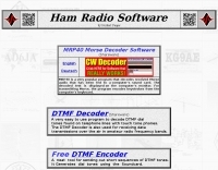 MRP40, a successor to the well-regarded MRP37, offers robust Morse code decoding capabilities by processing analog audio signals via a sound card and displaying the decoded text on a computer monitor. My own field tests with similar sound card decoders confirm that the quality of the audio input and proper signal conditioning are paramount for achieving reliable decoding, especially with _weak signals_. The program also facilitates CW transmission, converting keyboard input into Morse code to key a transceiver, a feature I've found useful for practicing sending or for quick contest exchanges. Beyond its core CW functions, MRP40 incorporates a convenient mini-logbook, which automatically checks for prior contacts and allows for quick logging by double-clicking callsigns in the receive window. This integration streamlines the logging process, a significant advantage during busy operating sessions where every second counts. The software also generates Morse tones using the sound card, a handy utility for testing tone sequences or for basic code practice. Additionally, the suite includes a DTMF decoder and generator, which can be used for decoding telephone dial tones or data transmissions over amateur radio frequencies. It also features MF-TeleType, a sound card-based audio data modem for transmitting text via radio, utilizing a principle similar to DTMF for encoding and decoding, offering a simple method for digital text communication.
 -
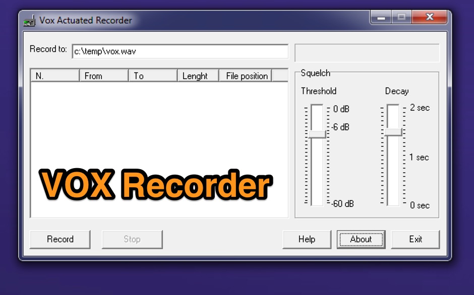 Vox Recorder is a specialized Windows utility designed for amateur radio operators, and radio listeners particularly those who use radio scanners. This software allows users to record audio from various sources, but it only activates when an audio signal is detected. This feature is particularly useful for avoiding the capture of silence or background noise, which can be common in radio scanning. By focusing on the audio signals, users can create cleaner recordings that are more relevant to their interests. The utility is user-friendly and tailored for hobbyists who want to document their radio listening experiences without the hassle of editing out silence later. Vox Recorder is an excellent tool for anyone involved in amateur radio, as it streamlines the recording process and enhances the overall experience of monitoring radio frequencies. Whether for personal use or for sharing with fellow enthusiasts, Vox Recorder helps ensure that every important transmission is captured effectively.
 -
 The Pfeiffer Maltese Quad Antenna System presents a unique approach to traditional quad antennas by utilizing a linear loading technique. This method effectively reduces the overall size of the antenna while maintaining its performance capabilities. Designed by Andrew Pfeiffer, the antenna's configuration resembles a Maltese cross, which not only enhances its structural integrity but also allows it to withstand challenging environmental conditions. This system is adaptable, offering various configurations from a 4-spreader Maltese Quad to a 16-spreader Maltese Quadruple-Cross, making it suitable for operators looking to optimize their setup without sacrificing efficiency. This antenna system is particularly versatile, covering multiple bands including 40, 20, 17, 12, and 10 meters. The design focuses on minimizing the physical footprint while ensuring effective signal transmission and reception. Amateur radio operators can benefit from the detailed plans available in the accompanying PDF, which outlines the construction process and specifications. Whether you're a seasoned DXer or a newcomer to the hobby, the Pfeiffer Maltese Quad Antenna System offers a practical solution for enhancing your station's capabilities.
 -
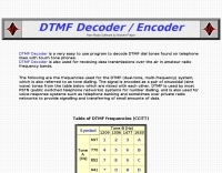 A very easy to use program to decode DTMF dial tones found on telephone lines with touch tone phones. The DTMF Decoder is also used for receiving data transmissions over the air in amateur radio frequency bands.
 -
 CWLab02 demonstrates a Windows-based software solution for Morse code enthusiasts, enabling both CW and CCW (Computer-Generated CW) sending and receiving within a single, integrated window. The program incorporates an improved CW interface, aiming to simplify the process of decoding and generating Morse code signals. It provides a straightforward method for hams to practice their CW skills or integrate computer-generated code into their operations, supporting real-time interaction with Morse code transmissions. The software's design focuses on ease of use for CCW operations, allowing operators to quickly generate and transmit code. While specific technical details on its decoding algorithms or WPM range are not provided, the emphasis on an "improved CW" suggests refinements in its signal processing capabilities. The ability to send and receive in the same window streamlines the user experience, offering a practical tool for training, casual QSOs, or integrating into a digital shack setup.
 -
 The "EZ-Tuner" is a homebrew automatic legal-limit antenna tuner that covers all amateur HF bands from 160-10 meters. Using a T-network design and controlled by a BASIC Stamp BS2sx microcontroller, the EZ-Tuner will match at least a 16:1 VSWR for either unbalanced or balanced transmission lines.
 -
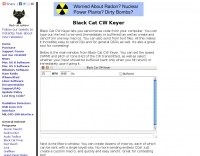 The **Black Cat CW Keyer** is a macOS application designed for amateur radio operators to transmit Morse code directly from their computer. It provides functionality for typing text to be sent, either immediately or buffered, and allows for the creation and transmission of pre-defined messages via single-key shortcuts. This software addresses the need for a flexible and accessible CW keying solution, particularly for Mac users who might find fewer dedicated ham radio applications compared to other operating systems. It integrates basic text-to-CW conversion, offering a straightforward interface for generating Morse code signals. Operators can utilize the Black Cat CW Keyer for various CW activities, including casual QSOs, contesting, or beacon operation. Its ability to buffer text allows for smoother transmission, while the single-key macro feature streamlines repetitive message sending, such as CQ calls or contest exchanges. While specific comparisons to other CW keying software are not detailed, its macOS focus provides a niche solution for Apple users. The program's utility lies in its direct approach to computer-based CW transmission, making it a practical tool for those seeking a dedicated **CW keyer** on the Macintosh platform.
 -
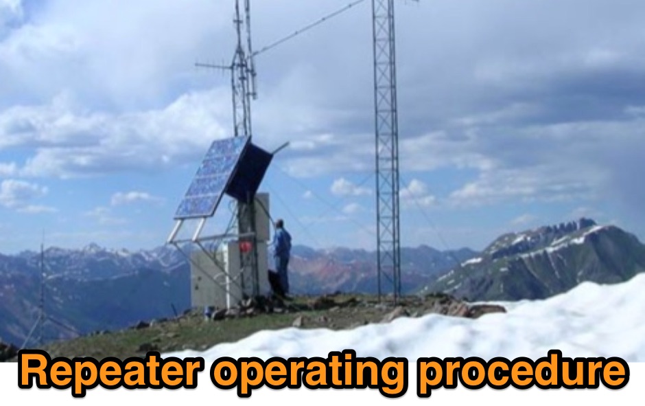 Outlines recommended operating procedures for amateur radio repeaters, detailing best practices for general on-air conduct. It emphasizes using simplex when possible, monitoring the frequency before transmitting, and maintaining concise, thoughtful transmissions to avoid monopolizing the repeater. The resource also stresses the importance of legal identification, such as the Canadian requirement at the beginning and end of a contact and every thirty minutes of operation. Furthermore, the article provides specific instructions for **autopatch** operation, including access codes and the necessity of brief calls, while cautioning against misuse for long-distance calls or commercial purposes. It highlights the financial support expected from regular users to maintain repeater infrastructure. Finally, the guide differentiates between permanently linked repeaters, which offer extended coverage, and **code access linked repeaters**, explaining the sequence of identification and code entry required to establish and terminate links for broader communication.
 -
 The project outlines the process for constructing a low-power FM broadcast transmitter using a Raspberry Pi Zero, a simple wire antenna, and battery power. It details the software installation steps for PiFM and MPG123, essential for generating and transmitting audio. The resource provides instructions for configuring the Raspberry Pi to broadcast FM signals, including command-line operations for initiating transmission and playing audio files. It specifically focuses on the Raspberry Pi Zero's capabilities for this application, highlighting its cost-effectiveness and minimal hardware requirements. The content presents a practical, hands-on approach to creating a basic FM transmitter, suitable for short-range, experimental broadcasting. It includes guidance on testing the FM output and ensuring proper operation of the software components. The project emphasizes the use of readily available components and open-source software to achieve functional RF output.
 -
 Presents a detailed construction guide for a **Quadrifilar Helix Antenna** (QHA) optimized for 137 MHz, specifically for receiving weather satellite transmissions. The resource outlines the author's experience building previous QHA designs, highlighting challenges with tuning and nulls, and then focuses on a refined design by John Boyer, documented by Steve Blackmore, which proved easier to build and yielded superior reception. The guide provides precise element dimensions, including 1.5m of 32mm PVC pipe for the mast and 8mm soft copper tubing for the helix elements. It specifies lengths for horizontal tubes (190mm, 90mm) and helix elements (903mm, 1002mm), along with instructions for drilling, assembly, and forming a **balun** by wrapping RG58 coax around the mast. The text emphasizes critical steps like ensuring elements are square and twisting in the correct direction to avoid phase issues. It includes references to original QST articles by Buck Ruperto (W3KH) and the WxSat program for decoding satellite transmissions, contextualizing the antenna's purpose. The article concludes with a sample NOAA 12 image from September 1998, demonstrating the antenna's reception capabilities.
 -
 Demonstrates the design and construction of a 9-element Yagi antenna for the **70 cm band** (432 MHz), based on the DK7ZB concept. The resource details EZNEC+ calculations for a single antenna, providing gain, sidelobe suppression, and front-to-back ratio figures. It also presents a comprehensive analysis of stacking two such antennas, including optimal stacking distance (1000 mm) and the resulting performance enhancements for the stacked array, such as an increased gain of 17.03 dBi. The article includes detailed drawings, wire file dimensions in millimeters, and azimuth/elevation plots for both single and stacked configurations. Practical construction steps are documented with original photographs, illustrating element mounting, the **28 Ohm matching system** using two quarter-wave 75 Ohm transmission lines, and the critical N-connector wiring. It also covers the iterative process of fine-tuning the driven element length to achieve a return loss of 20 dB, validating the EZNEC+ simulation results with actual measurements.
 -
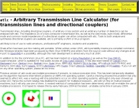 Unix or linux programme atlc calculates the impedance of electrical transmission lines of totally arbitrary cross section.
 -
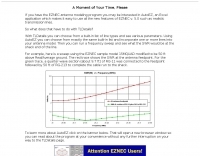
 Accurately determining an antenna's feedpoint impedance is crucial for optimal performance, especially when experimenting with new designs or making adjustments. While SWR meters provide basic information, a full complex impedance measurement reveals the resistive and reactive components, which are essential for proper matching. Modern antenna analyzers, like the _Palstar ZM30_ or MFJ259B, simplify this task, but measurements taken through a transmission line require careful interpretation due to impedance transformation. This resource details a calibration method to precisely account for the effects of the feedline. It explains how a transmission line can significantly alter the measured impedance, illustrating this phenomenon with a Smith Chart example where an 80m antenna's [22 + j6] Ohms feedpoint impedance transforms to [82 + j45] Ohms after a 10m line. The guide demonstrates using a transmission line calculator applet, such as the one by W9CF, to reverse this transformation. It outlines the process of calibrating a specific length of RG174 coax, showing how an initial 26ft estimate was refined to **25.85ft** to accurately predict a known 22 Ohm load, significantly improving accuracy over uncalibrated results.
 -
-
 A Smith charting program. You can enter either discrete components or transmission lines, see the results on screen and/or generate Postscript output. Component values can be changed numerically or using scrollbars.
 -
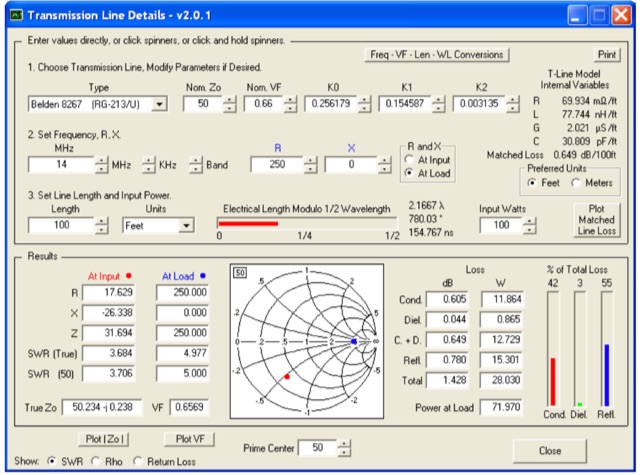
 Transmission Line Details. This utility program shows the impedance and SWR at both ends of a transmission line and the details of power loss in the line. It includes characteristics for over 40 built-in line types. You can modify these values to see how small changes affect the results or to specify custom lines. All program inputs may be changed directly or you can use spin buttons to make the changes. If you are using a moderately fast computer you can hold down a spinner and "watch the movie" on the charts as the results are recomputed. By AC6LA
 -
 Understanding Common Mode and Differential Mode Currents on Transmission Lines by K9YC
 -
 Don't neglect one of the most important parts of your station!
 -
 Radio wave propagation, Principles of transmission lines, Antennas
 -
 Millimeterwave/Microwave transmission lines and components, Cryogenic temperature application transmission cables and systems, Permittivity(Dielectric rate) and Permeabillity measurement systems, Antennas, Radar systems
 -
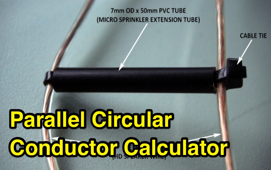 Design a parallel circular wire balanced transmission line with this online calculator. This calculator is a tool for designing balanced transmission lines with a specific desired characteristic impedance Zc and made of parallel circular conductors of a given diameter d.
 -
 Broadband over power lines (BPL) is a technique for transmission of high speed data (broadband Internet) over powerlines. Access BPL technology injects radio frequency energy into powerlines which were not designed for transmission of radio frequency energy, and leak substantial energy that causes interference to radiocommunications service
 -
 A Linux Smith charting program. You can enter either discrete components or transmission lines, see the results on screen and/or generate Postscript output. Component values can be changed numerically or using scrollbar
 -
 The collinear antenna, or Marconi-Franklin antenna, is an omnidirectional, high-gain antenna composed of in-phase half-wave dipoles aligned vertically. By using quarter-wave transmission line segments, it maximizes gain at a low horizon angle, outperforming a half-wave dipole. Adding segments increases gain but narrows bandwidth. A popular DIY version, the CoCo antenna, uses half-wave coaxial cable segments connected by non-radiating transmission lines. Built with stable velocity factor cables, a matching quarter-wave sleeve balun, and ferrite rings for attenuation, the antenna achieves performance comparable to commercial models.
 -
 A synthesized 2.3 GHz Amateur Television (ATV) transmitter design, conceived by Ian G6TVJ, is presented, targeting broadcast-quality video performance on the 13cm band and extending up to 2.6 GHz. The core of the design utilizes a commercial Z-comm Voltage Controlled Oscillator (VCO) that tunes from 2.2-2.7 GHz, providing a +10 dBm output and simplifying RF alignment. This VCO's stability, originally intended for narrowband applications, readily accepts high-frequency video modulation, contributing to the transmitter's robust performance. The exciter stage, incorporating a Mini Circuits VNA 25 MMIC amplifier, boosts the signal to +16dBm, while a Plessey SP4982 prescaler divides the output frequency for the synthesizer. The synthesizer employs a Motorola MC145151 CMOS parallel IC, favored over the common Plessey SP5060 for its superior video modulation characteristics and ease of programming without microprocessors. This choice addresses issues like LF tilt and distorted field syncs often seen with SP5060 designs, particularly when operating through repeaters or over long distances. The MC145151 divides the signal further, enabling precise frequency stepping, with programming handled by EPROMs for channel selection and LED display. The loop filter network, critical for video integrity, was developed through experimentation to prevent the PLL from reacting to video modulation, ensuring a clean transmitted picture. The transmitter incorporates a Down East Microwave commercial power amplifier module, delivering approximately 1.6W output, driven by the exciter through a 3dB attenuator. Construction involves surface-mount SHF components on micro-strip lines etched onto double-sided fiberglass board, housed within a tinplate box. The design boasts no AC coupling in the video path, preserving low-frequency response, a common failing in other ATV transmitters. Performance tests with a 50Hz square wave revealed no LF distortion, and a calibrated "Pulse & Bar" signal showed a near 100% HF response, demonstrating its capability for high-quality ATV transmissions.
 -
 Antennas, Transmission Lines, Tuners - Myths, Mysteries and Qualifiers By Don Wilhelm W3FPR
 -
 A dipole can be broadbanded by a number of techniques including by matching with resonant sections of transmission feed lines.
 -
 The resource, "Conventional Use of Transmission Line," meticulously details the operational principles of transmission lines, emphasizing the Transverse Electromagnetic (TEM) mode of energy transfer. It clarifies that for a line to function purely as a transmission line, all currents must be confined internally, with external fields ideally zero. The discussion differentiates between balanced and unbalanced lines, asserting that while both require equal and opposite currents within the conductors, the key distinction lies in the voltage relationship of each conductor to the surrounding environment. It highlights that a good antenna pattern does not inherently confirm proper feeder balance, and that common-mode currents can lead to RF in the shack and increased noise levels, even without pattern distortion. The article further explains that a transmission line can become a radiating conductor if energy is applied in a non-TEM mode, leading to common-mode issues. It cites classic texts like Jordan and Balmain's "_Electromagnetic Waves and Radiating Systems_" and Kraus's "_Antennas_" to support its definitions of TEM mode operation. The content also explores non-transmission line applications of parallel or concentric conductors, such as _coaxial dipoles_ and _folded dipoles_, which intentionally operate in non-TEM modes for antenna functionality. The author, _W8JI_, stresses that simply measuring equal currents is insufficient to confirm a balanced feeder; phase and voltage balance to ground are equally critical.
 -
 Smith Chart it is a graphic tool for solving transmission lines problems
 -
 Northern Connectors offers over 30 years of experience distributing specialized electro-mechanical connectors and related components, primarily serving industrial environments. The company partners with manufacturers such as _Binder_, _Hummel_, and _Mencom_, providing access to a broad range of connectivity solutions including circular connectors, heavy-duty connectors, and sensor cables. Their product lines are designed to address demanding technical requirements in various sectors, ensuring robust and reliable connections for critical systems. The resource details specific product categories like M5, M8, M12, M16, M23, and M40 connectors, alongside power and data transmission solutions. It emphasizes the availability of custom cable assemblies and overmolded solutions, tailored to unique client specifications. The site also highlights their technical support capabilities, assisting customers in selecting appropriate components for complex applications. Northern Connectors maintains a significant stockholding in the UK, facilitating prompt delivery of essential components. They focus on providing solutions that meet stringent industry standards for performance and durability.
 -
 Voldatech, a manufacturer based in China, produces a range of RF feeder cables and site components essential for amateur radio installations and telecommunication infrastructure. Their product line includes various types of coaxial cables, such as **50 Ohm** and 75 Ohm options, along with a comprehensive selection of connectors like N-type, UHF, and BNC. These components are critical for maintaining signal integrity and minimizing loss in antenna systems, whether for a home shack or a remote DXpedition setup. The company's focus on _RF Coax cables_ and connectors directly supports the needs of radio amateurs seeking reliable transmission lines for their transceivers and antennas. Amateurs often compare Voldatech's offerings to established brands, evaluating factors such as impedance matching, shielding effectiveness, and durability under various environmental conditions. The availability of diverse cable types allows operators to select optimal solutions for different frequency bands and power levels, from QRP to high-power amplifier setups. Their products are particularly relevant for those constructing new antenna arrays or upgrading existing feedline systems, aiming to achieve maximum power transfer and reduce standing wave ratio (SWR) for efficient signal propagation.
 -
 The DIY 137 MHz WX SAT V-dipole antenna project details the construction of a specialized antenna for receiving weather satellite transmissions. It provides specific dimensions for the dipole elements, designed for optimal reception around the 137 MHz band, which is commonly used by NOAA and Meteor weather satellites. The resource outlines the materials required, such as aluminum tubing for elements and PVC for the support structure, along with the necessary coaxial cable and connectors. The article presents a clear, step-by-step assembly process, including how to form the V-shape and connect the feedline. It emphasizes practical considerations for mounting and weatherproofing the antenna for outdoor deployment. The design focuses on simplicity and effectiveness for amateur radio operators interested in satellite imagery. Key aspects include the precise angle of the V-dipole and the lengths of the radiating elements, which are critical for achieving the desired circular polarization response for satellite signals. The resource includes photographic documentation of the construction phases and the final mounted antenna.
 -
 Documents S21RC's construction of an impedance transformer harness for a VHF/UHF cross yagi, utilizing 20m of _RG179_ cable. Details the creation of a DIY RF sampler with a -50dB sampling output, primarily for measuring HF radio PA section output with a Spectrum Analyzer, also applicable for _Pure Signal_ transmission. Chronicles the deployment of a 200m long beverage antenna for the _S21DX IOTA_ operation in 2022, positioned 2m above ground. Discusses the construction of a 3-element short beam for 10m to replace a previous 2-element antenna, with assistance from S21DW. Provides guidance on operating cheap _PA-70_ and _PA-100_ type Chinese SSPAs using IRF530 MOSFETs, emphasizing the necessity of a final LPF. Outlines the design and construction of a fully isolated interface for radio-to-computer connections, supporting various digital modes with isolated ground, audio transformers for IN/OUT, optical isolation for CAT/CIV, and isolated PTT/COS lines. Includes a log of software updates, such as the _HMI/TFT for NX8048K070_ and _2.1.14 Lite_ release with bug fixes for PEP hold and gradual watt decay.
 -
 Over 500 different types of high-performance electronic cables are manufactured by Alpha Wire, catering to demanding industrial and commercial applications. Their product lines include the robust _XTRA GUARD_ series, designed for harsh environments, and a range of flexible coaxial cables optimized for signal integrity. These cables are critical components in amateur radio shacks, industrial control systems, and data communication networks, ensuring reliable power and signal transmission. The company provides extensive technical resources, including detailed product specifications, application notes, and RoHS certificates, accessible through their online resource center. Hams often utilize their wire and cable products for antenna construction, station wiring, and various DIY projects requiring durable and reliable conductors. Alpha Wire also offers tools like size guides and competitor cross-references, simplifying product selection. They emphasize continuous uptime solutions, reflecting their focus on quality and durability.
 -
 PRO-LINK specializes in the manufacturing and distribution of high-quality cabling solutions, including a wide array of fiber optic cables and various coaxial cable types. Their product line encompasses 50-ohm and 75-ohm coaxial cables, essential for diverse RF applications, alongside specialized RF cables and 10Base-T networking cables. The company also provides a selection of connectors and custom cable harnesses, catering to specific installation requirements. Since 1988, PRO-LINK has offered a 5-year warranty on its products, underscoring a commitment to durability and performance. The product catalog details specifications for different cable constructions, such as _RG-58_, _RG-213_, and _LMR-400_ equivalents, which are commonly used in amateur radio installations for antenna feedlines and inter-component connections. Their offerings support both commercial and amateur radio operators seeking reliable signal transmission. The company's focus on robust cable and connector solutions addresses the critical need for low-loss transmission lines in radio communication systems, ensuring signal integrity across various frequency bands.
 -
 Microwaves101 provides an extensive repository of information covering fundamental principles of microwave design, targeting engineers and radio amateurs interested in the higher frequency spectrum. The site features a detailed _encyclopedia_ of microwave terms and concepts, alongside practical design considerations for various components and systems. It serves as a foundational reference for understanding RF propagation, transmission lines, and active/passive microwave circuits. The resource includes numerous calculators for impedance matching, filter design, and other critical RF parameters, facilitating hands-on project development. Discussions on **10 GHz** equipment and **24 GHz** projects highlight practical amateur radio applications, extending to operations up to 134 GHz. Content spans from basic theory to advanced topics like MMIC design and antenna characteristics, supporting both educational and practical endeavors in microwave technology.
 -
 This utility program shows the impedance and reflection coefficient parameters (SWR, reflection coefficient magnitude Rho, or Return Loss RL in dB) at both ends of a transmission line and the details of power loss in the line. It includes built-in specifications for approximately 100 different line types. You can modify the specs to see how small changes affect the results or to specify custom lines. All program inputs may be changed directly or you can use spin buttons to make the changes.
 -
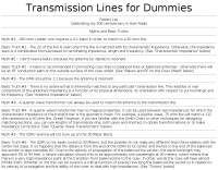
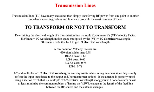 Transmission lines have many uses other than simply transferring RF power from one point to another. Impedance matching, baluns and filters are probable the most common of these.
 -
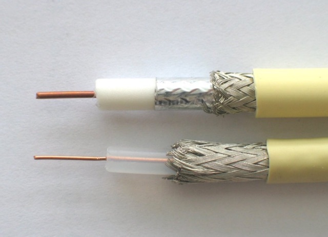 The feed line (also called the transmission line) is the RF power conduit between your radio and your antenna. The quality of your feed line is critical to your station. ARRL Article that explains differences among various commonly used feed line systems
 -
 The article explores the concepts of return loss, VSWR, and S11 within the context of microwave engineering, highlighting the confusion arising from their definitions. It clarifies that these parameters, while seemingly distinct, fundamentally describe the same phenomenon related to wave reflection and transmission in microwave circuits. The discussion emphasizes the historical context and mathematical relationships among these terms, revealing that their interpretation can vary significantly across different engineering disciplines. Ultimately, it advocates for a pragmatic approach to using these parameters based on familiarity rather than strict definitions.
 -
 This excel workbook addresses the issue of power loss in transmission lines with complex characteristic impedance ZoZo​. It illustrates the discrepancy between actual loss (0.35 dB) and matched line loss (0.6 dB) using a simplified example, highlighting potential software tool limitations. The RF Feedline Power-Loss Calculator provides accurate end-to-end loss assessments for both microwave and RF applications. This tool is suitable for engineers and students and is compatible with Windows versions of Excel 2016 or later, though it is not compatible with Macintosh systems.
 -
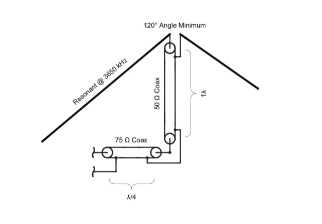
 This page by Arctic Peak provides a detailed explanation on how to use quarter-wave transmission lines as impedance transformers in ham radio antenna work. It explains how to match impedance values by connecting them with a λ/4 transmission line. The page also offers guidance on constructing your own transmission lines with specific impedance requirements, along with a calculator to determine the quarter wave length based on velocity factor and frequency. Useful for hams looking to optimize antenna performance and match transmission line impedance effectively.
 -
 This page provides a calculator to determine the total line loss and additional line loss in your transmission line based on the level of SWR. It helps hams understand the impact of high SWR on transmission line losses. The calculator allows users to input their SWR level and get accurate calculations of total losses. This tool is useful for ham radio operators looking to optimize their transmission setups and improve overall efficiency.
 -
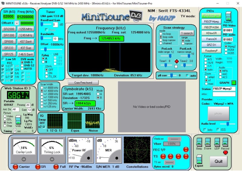 Receiving Digital Amateur Television (DATV) signals requires specialized software to interface with hardware tuners and decode the video stream. The _MiniTioune_ software, developed by F6DZP, serves this purpose, providing a Windows-based application for DVB-S and DVB-S2 reception and analysis. It is designed to work in conjunction with _MiniTiouner_ hardware, enabling hams to monitor DATV transmissions, including those from the QO-100 geostationary satellite. The resource outlines the initial setup process, including connecting the MiniTiouner hardware via a high-quality USB2 mini cable and running diagnostic test software. It details how to configure essential parameters such as symbol rate (SR), FEC rate, and DVB mode for various signal sources, from domestic satellite dishes to local DATV transmitters. Troubleshooting steps for common issues like "no video displayed" are also provided, often pointing to corrupted software filters or incorrect _Auto PID_ settings. Advanced features like the Web monitor for remote signal reporting and integration with _VLC_ media player for more tolerant decoding of non-DVB compliant signals are covered. The document also references a comprehensive user guide by W6HHC for the _MiniTiouner-Express_ system, which utilizes the same software, offering further in-depth assistance for operators.