Search results
Query: LF
Links: 622 | Categories: 7
-
 Ham Radio Club in Wales UK
 -
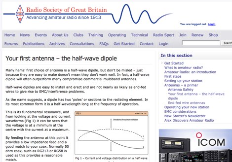 RSGB article for beginners. How to build a dipole antenna, construction tips and correct setup of inverted-ve dipole antennas
 -
 Operating in the **microwave** spectrum, Response Microwave, Inc. specializes in the design and manufacturing of RF and microwave signal processing components and subsystems. The company's product line encompasses a wide array of offerings, including Connectivity Series components, rotary joints, phase shifters, cable assemblies, surge protectors, terminations, Hybridline/Couperline products, circulators/isolators, directional couplers, quadrature hybrids, attenuators, custom assemblies, filters/diplexers, DC blocks & bias tees, power dividers/combiners, laser diodes & drivers, high-frequency connectors, and precision test accessories. This extensive catalog supports various applications requiring precise signal manipulation and transmission at elevated frequencies. The resource provides access to a comprehensive product catalog and a dedicated connector catalog, detailing specifications for components like **high-frequency connectors** and test cables. While specific performance data or comparative analyses are not directly presented on the main page, the breadth of products indicates a focus on providing foundational building blocks for microwave systems. The company emphasizes customer service and aims to be a reliable source for RF/Microwave/Optics product requirements, serving a growing customer base with its specialized component offerings.
 -
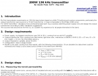 A transmitter project for the 136 kHz band by IK2PII
 -
 Microprocessor based interface designed receives a signal from a Morse key, processes it, and re-transmits it to the radio. A microprocessor in the circuit is pre-programmed with a proprietary algorithm which makes a number of measurements and adjustments to the less percise human generated code.
 -
 Designing and constructing a two-element receiving loop antenna array for HF operation involves specific considerations for achieving high directivity and noise reduction. This resource details a homebrew system comprising two 30-inch diamond-shaped loops, spaced 20 feet apart, which are fed through mast-mounted preamplifiers and passive signal combiners. The operational principle relies on adjusting phase delays between elements via precise _Belden 8241_ coaxial cable lengths, optimized for specific bands from 160m to 20m. Performance data, derived from _EZ-NEC_ modeling, illustrates consistent 90° azimuth-plane beamwidth and low take-off angles across the target bands, with _Receiving Directivity Factor_ (RDF) values comparable to a 300-foot Beverage antenna. The article presents detailed elevation and azimuth plots for 20m, 30m, 40m, 80m, and 160m, demonstrating the array's ability to provide strong response at low DX angles while also supporting _NVIS_ signals. Key components like the _DX Engineering RPA-1_ preamplifier and _DXE RSC-2_ signal combiner are discussed, alongside the importance of impedance matching to preserve antenna patterns. The construction emphasizes self-contained elements that do not require ground radials, offering a compact solution suitable for suburban environments and stealth installations, with a focus on optimizing receive performance independently from transmit antennas.
 -
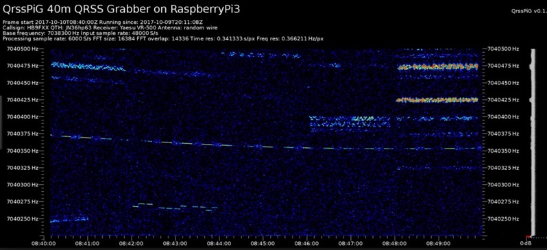 Monitoring extremely weak signals in the QRSS (Very Slow Morse) mode requires specialized receiving and processing capabilities to extract information below the typical noise floor. This project provides a software solution, _QrssPiG_, designed to run on a Raspberry Pi, enabling it to function as a dedicated QRSS grabber. It interfaces with various Software Defined Radio (SDR) devices, including the popular _rtl-sdr_ dongles and _HackRF_ units, to acquire raw I/Q data streams. The software then performs the necessary signal processing to visualize and decode these faint, long-duration CW transmissions, often operating with milliwatts of power. The system leverages the computational power of the Raspberry Pi for real-time signal analysis, allowing hams to participate in QRSS experiments and monitor distant beacons. It supports different SDR hardware, offering flexibility in setup and deployment for home stations or remote monitoring sites. The project includes detailed instructions for installation and configuration, making it accessible for those familiar with Linux environments. This grabber is particularly useful for tracking propagation on the LF and HF bands where QRSS activity is common, providing a visual representation of signal presence over extended periods.
 -
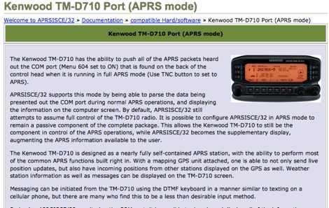 The Kenwood TM-D710 is designed as a nearly fully self-contained APRS station, with the ability to perform most of the common APRS functions built right in.
 -
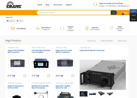 XieGu Tech manufactures quality amateur radio transceivers and amplifiers designed by BG8HT. Xiegu focus is portable and self contained transceivers perfect for your next SOTA, hiking trip or travel experience.
 -
 Magnetism is manifested as a 'field of vectors', that is, any point in the magnetic field has not only a magnitude, but a direction in space. The four Maxwell equations describe how electric and magnetic vector fields behave and interact.
 -
 A microprocessor based interface designed to go between a standard Morse code key and a radio transmitter. The circuit receives a signal from the key, processes it, and re-transmits it to the radio.
 -
 DF0WD DL4YHF Longwave Station include a linear transverter and antenna tuner
 -
 Product specialist for semiconductors and electron tubes based in Belgium
 -
 A high speed, self discovering, self configuring, fault tolerant, wireless computer network that can run for days from a fully charged car battery with focus on emergency communications
 -
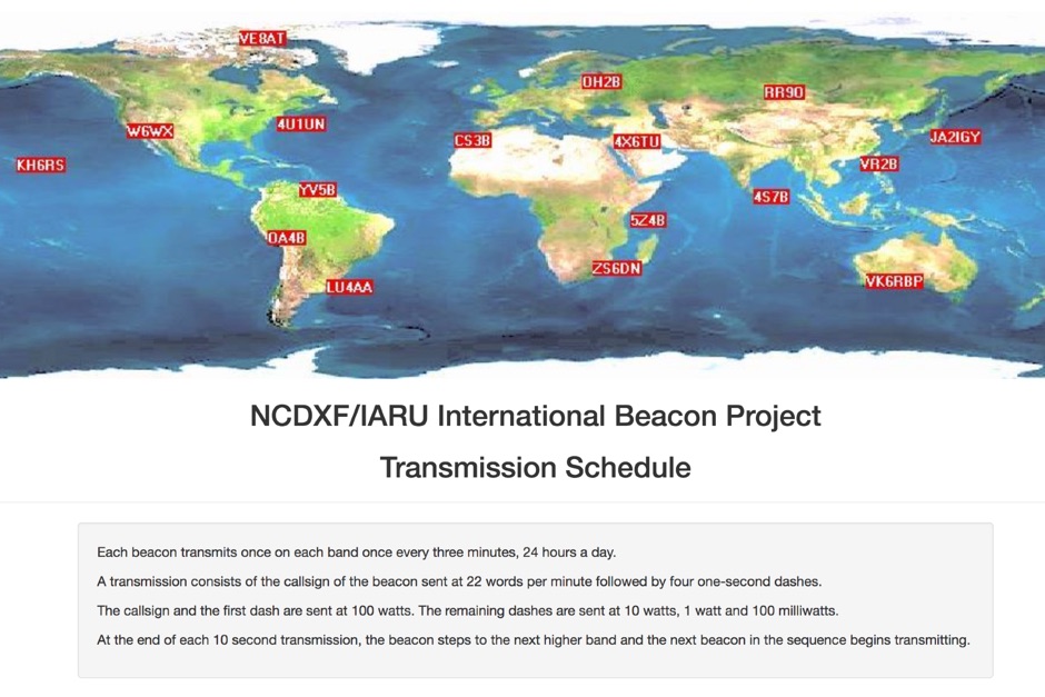 Whatch at beacons transmitting in real time. This page contains a self refreshing table that displays every 10 seconds the current transmission schedule of the international beacon project. Tune your radio and check the beacon you are hearing.
 -
 Constructing an End-Fed Half-Wave (EFHW) antenna offers a practical solution for HF operators seeking a multiband wire antenna without the need for extensive radial systems. This design typically employs a high-impedance transformer at the feed point, matching the antenna's inherent high impedance to a 50-ohm coaxial feedline. The article specifically details a 2012 approach, focusing on a transformer with a 49:1 turns ratio, which is a common configuration for EFHW antennas. The resource outlines the construction of a wire element cut for a half-wavelength on the lowest desired band, with specific coil arrangements enabling operation on harmonically related bands such as 40m, 20m, and 10m. It discusses the physical dimensions and winding details for the matching transformer, often utilizing a ferrite toroid core to achieve the necessary impedance transformation. The content provides insights into the operational principles and practical considerations for deploying such an antenna, including methods for tuning and optimizing performance across multiple amateur radio bands. While acknowledging that the presented information from 2012 may be superseded by newer insights, it serves as a foundational reference for understanding EFHW antenna theory and construction.
 -
 Small, vibrant and active group of Amateur Radio Operators residing in the counties of Guilford, Randolph, and Davidson in central North Carolina.
 -
 Presented is a historical collection of short-wave listening (SWL) QSL cards, primarily from the late 1930s and early 1940s, offering a glimpse into early international broadcasting and the technical pursuits of SWL operators like Les Miles during that era. The resource showcases specific QSLs from stations such as _Broadcasting Corporation of Japan_, _XGOY - The Central Broadcasting Administration_ in Chungking, China, and _Australian broadcasting ship, Kanimbla VK9MI_, each with reception dates and frequencies like 11.90MHz or 9.525MHz. It highlights the self-sufficiency of SWL enthusiasts who constructed and maintained their own radio and test equipment, evoking the sensory experience of vintage valve receivers. The collection provides concrete examples of international broadcast stations active before and during World War II, including _2RO3 - Rome_ and _WRUL - World Wide Broadcasting Foundation_ from Boston. Each QSL entry details the station, location, reception date, and often the frequency, such as 9.63MHz or 11.26MHz, allowing for historical verification of broadcast schedules. The resource also briefly mentions the operational details of the _VK9MI_ offshore radio station, directing readers to further information on its history. This compilation serves as a tangible record of global radio communication during a pivotal historical period.
 -
 Waldo County Amateur radio club. We are a club that supports the greater Belfast area and Waldo County ham community.
 -
 The ZS1J/B beacon operates on 28.2025 MHz with 5 Watts output to a half-wave, end-fed vertical antenna, initially installed in 1977 as ZS5VHF near Durban. The 10-meter transmitter is a modified 23-channel CB radio, and the identification keyer uses a diode matrix unit with TTL ICs from the same era. After relocation to Plettenberg Bay in 1993, the beacon has been in continuous service, with additional QRP transmitters later installed for other bands. In 1994, a single-transistor, 80-meter, 0.5-watt QRP transmitter with a half-wave dipole was added on 3586 kHz, followed by a 160-meter, 0.5-watt unit on 1817 kHz. A 30-meter, 0.5-watt transmitter was installed in 1996, operating on 10.124 MHz. In 2002, a 40-meter QRRP beacon on 7029 kHz, with an output of 100 microwatts, achieved DX reports up to 1100 km from ZS6UT in Pretoria. Best DX reports for the 80m and 160m beacons came from 9J2BO.
 -
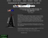 The Greenwood Amateur Radio Society consists of a group of people who share a common interest in Amateur Radio. Our goal is to further the exchange of information and cooperation between members, to deepen our radio knowledge, improve our operating skills, and to advance the general interest and welfare of Amateur Radio in our community
 -
 Welcome to our line of Low Frequency, Natural Radio Research, Broadcast, Marine and Shortwave products. Our evolving product line is the result of our dedicated research efforts primarily in the areas of LF, VLF, MF, and HF.
 -
 Low-frequency (LF) radio time signals, operating primarily in the 40–80 kHz range, are broadcast by national physics laboratories for precise clock synchronization. Transmitters like **JJY** (40 kHz, 50 kW; 60 kHz, 50 kW), RTZ (50 kHz, 10 kW ERP), MSF (60 kHz, 15 kW ERP), WWVB (60 kHz, 50 kW ERP), RBU (66.66 kHz, 10 kW), and DCF77 (77.5 kHz, 50 kW) cover vast geographic areas, often several hundred to thousands of kilometers. LF signals offer distinct propagation advantages over higher-band transmissions such as GPS. Their long wavelengths (3–6 km) enable effective diffraction around obstacles like mountains and buildings. The ionosphere and ground act as a waveguide, eliminating the need for line-of-sight and allowing a single powerful station to cover extensive regions. Ground wave propagation minimizes ionospheric variability effects on transmission delay, and signals penetrate most building walls effectively. Robust and low-cost receivers, often priced at 20–30 USD/EUR, are widely used in radio clocks. These receivers typically comprise a tuned ferrite core antenna, a receiver IC (e.g., Atmel T4227, U4223B, MAS1016) for amplification and AM detection, and a microcontroller for decoding the time signal and phase-locking a local clock. Specific components for DCF77, MSF, and WWVB are readily available from vendors like HKW Elektronik and Ultralink.
 -
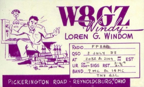 The Windom antenna, one of the oldest antennas developed for amateur use, has had a complicated history, one as interesting as the theory of the antenna itself.
 -
 This resource provides a historical analysis of amateur radio call sign assignment policies in the United States, detailing regulatory shifts from the Department of Commerce to the Federal Radio Commission (FRC) and subsequently the Federal Communications Commission (FCC). It documents the evolution of call sign issuance, from early reissuance practices in the 1920s to the implementation of the Group Call Sign Assignment System on March 24, 1978. This system categorized call signs (e.g., 1x2, 2x1, 1x3, 2x3 formats) into groups A, B, C, and D, correlating with license classes such as Extra, Advanced, General, and Novice, and specifying prefixes for contiguous U.S. and territorial areas (e.g., _AH_, _KP_, _KL_). The document further details the legislative process leading to the modern Vanity Call Sign program, initiated by a petition in June 1990 and formalized by the Omnibus Budget Reconciliation Act of August 10, 1993. It outlines the FCC's adoption of final rules on December 23, 1994, and the subsequent fee structure, with the first vanity call sign issued on May 31, 1996, at a cost of **$30.00** for a ten-year term. The ARRL's proposed "starting gates" implementation strategy is also described, which phased in eligibility for vanity call signs based on license class and prior holder status. DXZone Focus: Historical Document | Regulatory Analysis | Call Sign Formats | Fee Structure
 -
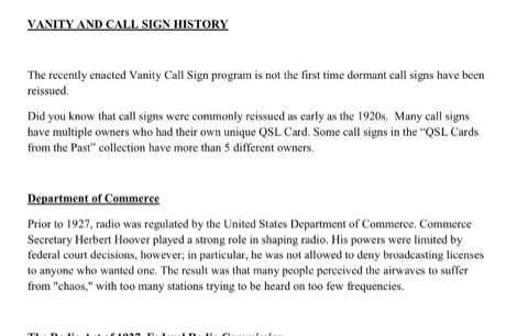
 Accessing antennas at great height poses many potential safety hazards. Essentially, climbing ladders or scaling towers, regardless of whether or not a commercial safety harness is fitted, is risky business indeed particularly for those hobbyists in their latter years or not as physically capable as others.
 -
 An interesting article on end fed half-wave wire antennas with a couple of original experiments. Author illustrate the role of the QRP matchbox, and a 40/20 meter antenna with a center stub making it a large bandwidth antenna for 40 and 20. Includes also an 80/40 end fed with the typical coil to make it available on 80 merts band.
 -
 Hamradio, Webcams, Radio and TV-Links by DF3SP Walter
 -
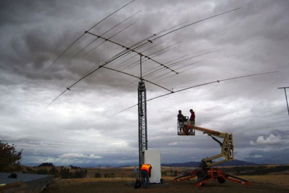
 While there are quite a few standalone Morse Code or CW decoders out there, I wanted to tackle the problem myself and end up with both a great Arduino learning project and a decent portable decoder for when I'm out in the field operating QRP
 -
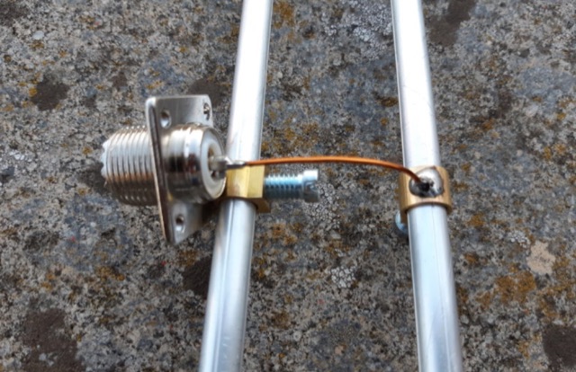
 A rotary dipole antenna for 30 meters band. Each arm is about 12.5 ft and is constructed from telescoping fibreglass flag/fishing poles and short lengths of aluminium tubing. Two short lengths of glass-fibre rod were used to insulate the arms from the supporting hardware.
 -
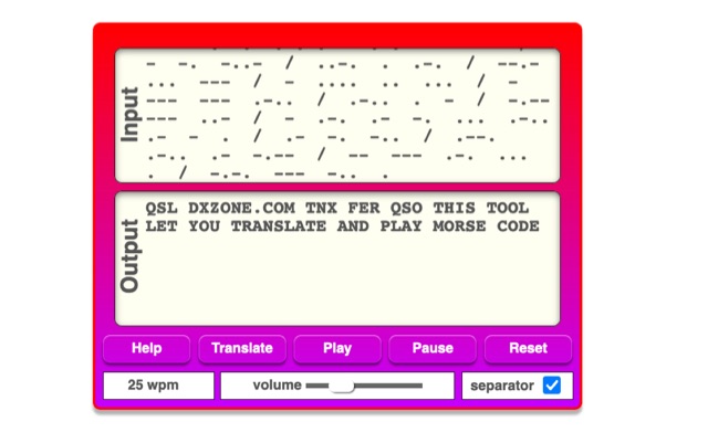 The online Morse code translator and decoder provides functionality for converting plain text into Morse code and decoding Morse code back into text. Users can input text directly into a designated box for translation to Morse, with the tool ignoring characters that lack a Morse equivalent. Conversely, Morse code can be entered using periods for dots and minus signs for dashes, requiring a single space to separate letters and a forward slash to delineate words. The interface also supports direct Morse input via a button, where a half-second pause separates letters and a 1.5-second pause separates words. The resource details the historical context of Morse code, noting its invention by _Samuel F.B. Morse_ in the 1830s for telegraphy, and its continued use by amateur radio operators for recreational purposes and emergency signaling, such as the **SOS distress signal**. Guidance on learning Morse code suggests using online translators for practice and listening to amateur radio transmissions. The tool offers an audio playback feature for translated Morse, allowing users to hear the code at various words per minute (WPM) settings. It also includes a visual chart to aid in memorizing the dot and dash sequences for the alphabet.
 -
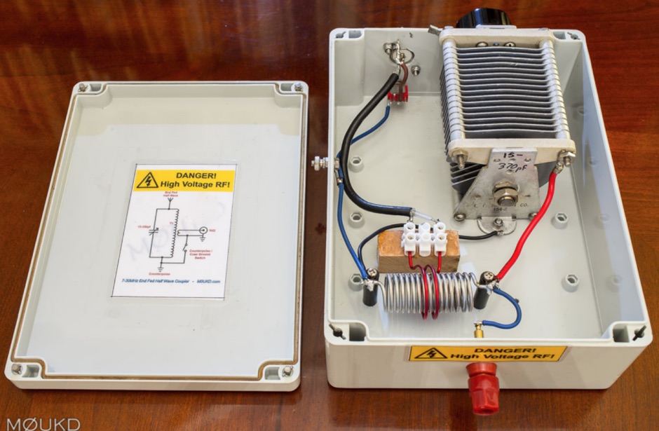 A home made end-fed half-wave antenna coupler with antenna lenght calculator and counterpoise calculator based on center frequency. Includes pictures and drawings along to antenna homebrewing instructions with a home made on air wound transformer
 -
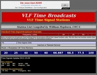 VLF Time Signal Stations, Station List Compiled by William Hepburn, LWCA
 -
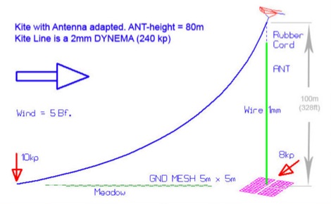 An essential kite antenna plan for the top band, Antenna has been tested at half wave and quarter wave.
 -
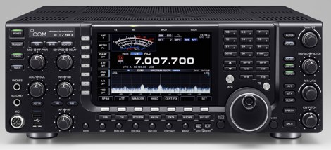 Exaustive review of the self-contained, top-performance HF/6m transceiver Icom IC-7700
 -
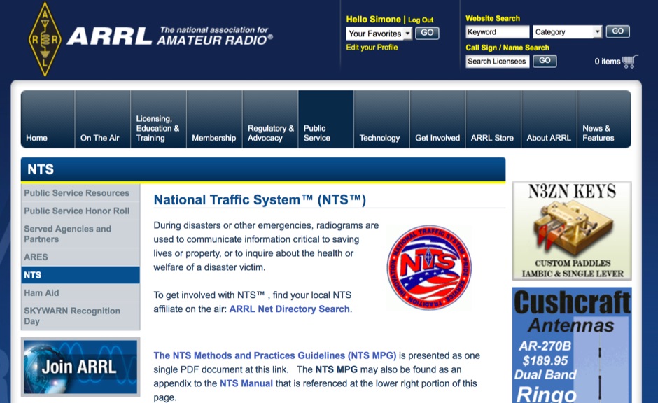 ARRL National Traffic System, During disasters or other emergencies, radiograms are used to communicate information critical to saving lives or property, or to inquire about the health or welfare of a disaster victim.
 -
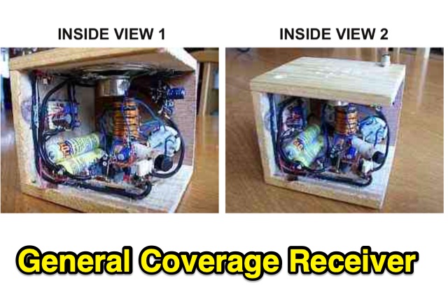 This is a compact three transistor regenerative general coverage receiver with fixed feedback. The sensitivity and selectivity is relative good, especially on the LF and MW bands, as can be expected with this simple design.
 -
 Author experiments end fed half wave antennas using common two conductore speaker wire, this article features a couple of end-fed halfwave wires for the 40M and 20M bands.
 -
 High Speed Multimedia (HSMM) radio, as introduced by John Champa, K8OCL, represents a significant advancement in amateur radio's digital capabilities, moving beyond traditional keyboard modes like packet radio. This initiative, driven by ARRL's Technology Task Force, focuses on developing high-speed digital radio networks capable of up to 20 megabits per second. HSMM primarily facilitates digital voice (DV) and digital video (ADV), enabling real-time video transmission from emergency scenes to an EOC without expensive ATV gear, often requiring only a laptop, a PCMCIA card, a digital camera, and a small antenna. The working group's initial efforts concentrate on cultivating microwave skills within the amateur community to build and support portable and fixed high-speed radio-based local networking, or **RLANs**. These networks prove invaluable for RACES and ARES organizations, as well as homeland security and other emergency communications. Field Day exercises and simulated emergency tests (SETs) are encouraged to hone skills in rapid site surveys and deploying broadband HSMM microwave radio networks, with examples like linking Field Day logging stations or antenna test results at the Midwest VHF-UHF Society Picnic 2003. Getting started with HSMM often involves adapting off-the-shelf **IEEE 802.11** (WiFi) equipment to comply with amateur radio regulations, typically operating in the 2.4 GHz ISM bands. While consumer WiFi gear has range limitations under Part 15 rules, proper setup under amateur regulations can extend coverage significantly, with test networks like the Hinternet achieving 5-15 mile ranges at 54 M bit/s using small mast-mounted dish antennas. Careful selection of equipment with external antenna ports, high transmit power, and low receive sensitivity is crucial, along with using low-loss coaxial cable like LMR-400 for optimal performance at these frequencies.
 -
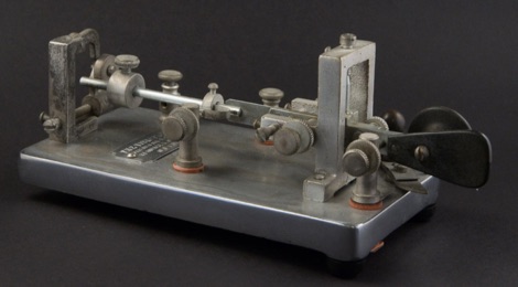 The Vibroplex Collector’s Page details the history and identification of Vibroplex semi-automatic telegraph keys, commonly known as "bugs." It traces the evolution from Horace G. Martin's 1902 Autoplex, which required a battery, to the fully mechanical Vibroplex patented in 1904. The resource explains how these keys generate automatic dots and manual dashes, helping telegraphers mitigate Repetitive Motion Disorder (RMD) and increase sending speed, thus improving their earnings. The site also covers the initial design by Alfred Vail in 1844, Jesse Bunnell's 1881 "Triumph Key," and William O. Coffe's 1904 "Mecograph." This page assists owners in identifying their Vibroplex models and determining their manufacturing dates, providing insights into the company's long history and notable figures like J. E. Albright. It notes that approximately 300,000 Vibroplexes have been produced since 1904, with the Original model still in production after more than 90 years. The resource also touches upon various Vibroplex models, including unusual, scarce, and common types, alongside legal and illegal clones from other manufacturers.
 -
 Elfa Distrelec, european distributor of electronics
 -
 This page delves into the Inverted V antenna, a source of myths among ham radio operators. The author explores the behavior of this antenna type with a focus on a 20m half-wave dipole positioned 10m above the ground. From Pythagoras to high school math, the article simplifies the calculation of dimensions and angles for setting up an Inverted V antenna. It includes a spreadsheet for calculating hypotenuse length and angles, crucial for antenna setup. Additionally, it provides insight into the radiation pattern of a 'flat' half-wave dipole at 10m height. Useful for hams planning to optimize their antenna setup. In Norwegian.
 -
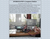
 DF0WD/DL4YHF's Longwave Overview details amateur radio operations on the 135.7 to 137.8 kHz segment in Germany. The author outlines the "inofficial" European band plan, specifying segments for QRSS, TX tests, beacons, conventional CW, and data modes. Early LF activities at DF0WD began with a 20-watt CW transmitter, later upgraded to a homemade linear transverter capable of 100 watts, driven by an Icom IC706 on 10.137 MHz. The station's antenna system includes a 200-meter wire, approximately 10 meters above ground, supported by football field light-masts. Despite its length, the antenna's efficiency is noted as very low due to the immense wavelength of about 2.2 km. The author's experience highlights the significant challenge of achieving effective radiated power (EIRP) on LF, estimating DF0WD's EIRP at around 80 milliwatts based on field strength measurements from PA0SE. DF0WD/DL4YHF has successfully worked numerous countries on 136 kHz CW, including DL, F, G, GI, GM, GU, GW, HB9, HB0, LX, OE, OH, OK, OM, ON, OZ, PA, and SM. The author also mentions ongoing efforts to log contacts with CT, EI, LA/LG, and to complete a two-way QSO with Italy, demonstrating persistent activity on this challenging band.
 -
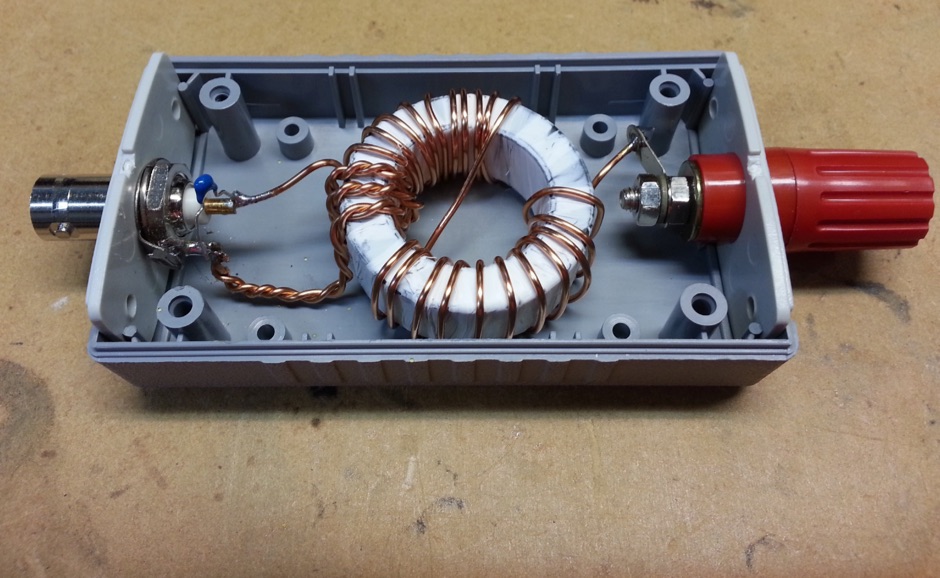 An end-fed half wave antenna matching unit made of 3:24 turns ratio on a FT140-43 toroid with a 150pF capacitor across the input.
 -
 The BikeLoop antenna project details the construction of a double magnetic loop antenna optimized for VLF frequencies, specifically around 136 kHz. This innovative design incorporates two orthogonal loops, which significantly enhance reception capabilities. Key construction hints include utilizing lightweight bicycle rims for the antenna structure, making it easy to transport and set up in various locations. The document provides valuable mathematical and electrical insights into the antenna's performance, alongside practical reception tests conducted in the Italian Alps, showcasing its effectiveness in capturing various VLF signals, including Sferics and FSK transmissions. Proper setup is crucial for optimal performance. The project emphasizes the importance of grounding and avoiding interference from nearby electrical sources. The reception tests revealed the antenna's ability to capture a range of signals, demonstrating its practical application for enthusiasts interested in VLF reception and antenna experimentation. Overall, the BikeLoop serves as an excellent starting point for those looking to explore the world of VLF frequencies and enhance their antenna-building skills.
 -
 The ARRL's End-Fed Half-Wave (EFHW) Antenna Kit is an easy-to-build four-band antenna designed for 10, 15, 20, and 40 meters. Ideal for portable operations, it includes a 49:1 impedance transformer for compatibility with most transceivers. This project, detailed with step-by-step assembly instructions, involves creating a weatherproof enclosure and impedance matching network. The kit simplifies HF operations and supports multiple configurations, making it a versatile tool for amateur radio opertors.
 -
 Heinrich Hertz was the first to send and receive radio waves.
 -
 This is a simple half wave antenna for 70 cm band, made using the jpole design.
 -
 A large collection of electronic components symbols in spanis
 -
 Yamuna Cable Accessories Pvt. Ltd. specializes in the development, manufacturing, and marketing of power cable accessories, including a comprehensive range of cable jointing kits and components. The product line encompasses _Heat Shrink_ and _Cold Shrink_ cable joints, heat shrinkable tubing, pre-moulded slip-on joints, resin pour, and Tapex systems, all designed for applications up to 66 kV. The company highlights its ISO 9001-2015 certification, signifying adherence to international quality management standards in its manufacturing processes. The resource details specific product categories such as end caps, insulation piercing connectors, copper mesh, fireproof coatings, tubing and components, lugs and ferrules, and safety products. It also features specialized items like _Elbow Connectors_ rated for 25 kV-250, 400, and 630 amps, and various types of tinned copper braid used for grounding and electrical shielding. The site provides an overview of their manufacturing capabilities and global presence across 40+ countries. Established in 1973, Yamuna Densons has over four decades of experience in the industry, positioning itself as a significant designer, manufacturer, and supplier of insulators, tabs, and cable jointing systems in India. The company emphasizes its role as a leading exporter of these products, serving both domestic and international clients.