Search results
Query: ar 144
Links: 92 | Categories: 0
-
 During a club's "Filetto Day" event, a comparative field test was conducted between a **Buddipole** antenna and a homemade 20/40-meter wire dipole. The author, IW5EDI, performed this personal evaluation from a mountain top at 1500 meters above sea level, utilizing a Yaesu FT-857D transceiver to switch between antennas. The observations on the 20-meter band indicated that the wire dipole consistently delivered significantly stronger signals compared to the Buddipole. Additionally, the Buddipole exhibited higher levels of **QRM** during the listening tests. The commercial Buddipole, known for its multiband capability and compact size with a self-supporting tripod, was contrasted with the simpler, larger wire dipole, which required a fiberglass fish pole for support. This direct comparison highlights practical differences in performance and deployment between a popular portable commercial antenna and a basic wire antenna in a real-world operating environment.
 -
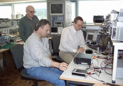 Report on tests done on VHF Radios to understand which are best suited for 144 MHz operation in large signal environments like VHF contests
 -
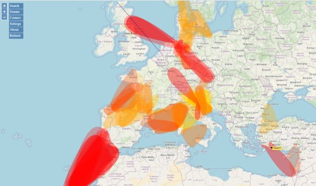 VHF – Based on realtime APRS reports. This map shows real-time radio propagation from stations operated near 144 MHz. It uses data gathered by Automatic Packet Reporting System-Internet Service (APRS-IS) from packet stations in the amateur radio service. The map shows activity from the past hour. Paths are smoothed to create a color-coded footprint indicating the distance VHF signals are likely to be traveling.
 -
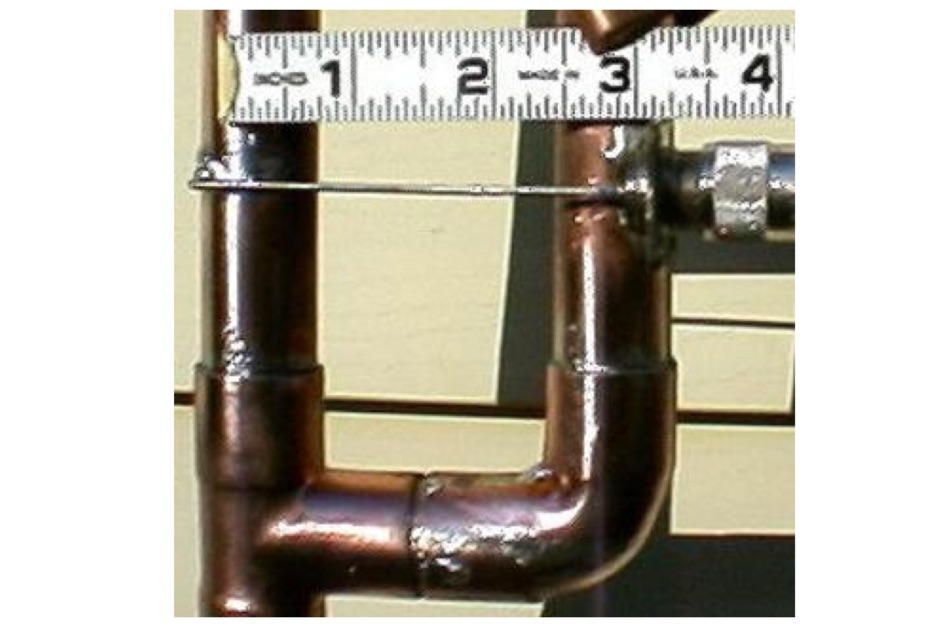 A copper J Antenna for 144 and 430 article with design, feeding methods and pictures
 -
 Such kind of omnidirectional antenna gives the possibility to be QRV with horizontal polarisation, as commonly used for the CW and SSB section of the 2m band. This actual design shows a 1.3:1 bandwidth of about 150kHz, centered to 144.200MHz.
 -
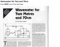 G8ACC article project for a 144 & 430 MHz wavemeter
 -
 The MMMonVHF database, curated by DL8EBW, currently lists 63,455 entries for VHF operators, providing a searchable resource for locating stations active on 144 MHz and higher bands. Operators can register their callsigns to be included, with specific criteria such as participation in _MS_ (Meteor Scatter), _WSJT_ modes, or _EME_ (Earth-Moon-Earth) operations required for inclusion in the `call3.txt` file. This resource facilitates VHF DX expeditions and contest planning by allowing users to identify potential contacts within a geographical area. The database supports various VHF/UHF operating modes, including those focused on weak signal propagation. Statistical data regarding the database entries is also presented, offering insights into the distribution of registered VHF activity.
 -
 Providing amateur radio 144 MHz & 440 MHz repeaters in the state of Oregon
 -
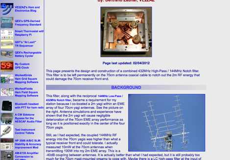 Combined 432 MHz High-Pass - 144 MHz Notch Filter By Bertrand Zauhar, VE2ZAZ
 -
 A great and efficient monoband VHF portable antenna. The article consist of two version of a 12.5 Ohm 3 elements yagi beam antenna plans for the two meter band, a full sized and a shortened version expecially designed for the SSB and CW on 144 MHz.
 -
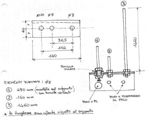 A multiband J-Pole antenna project that cover 144,220 and 430 MHz. The articles includes several pictures of this multi-band antenna, including handmade schematics and diagrams, project is mainly in Italian
 -
 Presents a historical timeline of amateur radio satellites, beginning with the inaugural _OSCAR 1_ in 1961 and extending through ARISSat-1 in 2011. It outlines the evolution of these orbiting transponders, initially simple battery-operated beacons, into sophisticated platforms supporting educational initiatives, emergency communications, and technology demonstrations. The document highlights the significant contributions of various AMSAT organizations and other entities in developing and deploying these spacecraft. Each entry provides specific launch details, including the date, launch vehicle, and initial orbital parameters such as apogee, perigee, and inclination. For instance, AMSAT-OSCAR 7 (AO-7) launched in 1974 into a 1459.00 x 1440.00 Km orbit, while AMSAT-OSCAR 40 (AO-40) achieved a highly elliptical 58665.00 x 1157.00 Km orbit. The resource also notes the allocated amateur satellite service frequencies, including 29 MHz (10m), 145 MHz (2m), 435 MHz (70cm), 1270 MHz (24cm), and 2400 MHz (13cm). The compilation serves as a concise reference for understanding the progression of amateur satellite technology and operations over five decades, showcasing the collaborative efforts of the global amateur radio community in space communication endeavors. It details the physical characteristics and project affiliations for many of the **20** satellites listed, providing a foundational historical context.
 -
 The purpose of this article is to provide radio amateurs with enough background information to understand the technical challenges involved in small-station digital EME on the 144 and 432 MHz bands.
 -
 HamGear.eu page about the FT-100, 160 to 6 meter bands plus the 144 MHz and 430 MHz bands transceiver from Yaesu.
 -
 Developing operational amateur radio equipment for the 134 GHz band presents significant technical challenges, particularly in frequency generation and stability. This resource details the construction of a 134 GHz system, outlining its architecture with separate transmit (Tx) and receive (Rx) modules, each employing a local oscillator (LO) and RF head units. The system utilizes a dual Flann 50 GHz lens-type horn antenna configuration for optimal signal coupling. The transmit path incorporates an LMX2541 synthesizer chip operating at approximately 2.8 GHz, referenced by a 10 MHz double-oven Morion OCXO for exceptional stability. This signal is multiplied through a series of stages (X4, then X2) to generate a 22.4 GHz signal, which subsequently drives a dual series diode multiplier to produce the final X6 signal for 134 GHz operation. The receive side features an anti-parallel diode mixer coupled to a 144 MHz transceiver via a preamplifier, ensuring effective downconversion. Operational mode is CW, achieved by keying a multiplier stage. The project includes images of the Tx and Rx head units and describes a successful 3.5 km test with G8ACE, demonstrating stable signal tones due to PLLs locked to OCXOs at both ends, confirming the system's robust performance.
 -
 If your antenna is fixed in one direction, you will notice that your antenna works perfectly only during fall and spring.
 -
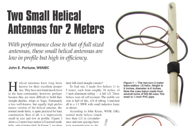 This article is about two excellent small helical antennas for the two meters band. With performance close to that of full sized antennas, these small helical antennas are low in profile but high in efficiency.
 -
 These pages containing informations about contesting on 144MHz and higher bands. All informations are only in Czech language.
 -
 The CQ Contest & DX Group, main activities is - participating in contests. Mainly in the Nordic Activity Contest at the 50 MHz, 144 MHz and 432 MHz, though the group holds a full licence, have we not participated in a HF contest yet.
 -
 The Baofeng UV-5R handheld transceiver, introduced around 2012, operates across the 2-meter (144-148 MHz) and 70-centimeter (420-450 MHz) amateur bands, offering dual-band receive and transmit capabilities. This review provides an early assessment of the radio's form factor, user interface, and general performance, noting its compact size and the inclusion of a **VFO/Memory mode** button for frequency management. The device supports both FM and narrow FM modes, with a reported power output of 4 watts on VHF and 3 watts on UHF, making it suitable for local simplex and repeater operations. Key features discussed include its 128-channel memory capacity, a built-in VOX function, and a **DTMF keypad** for tone dialing and repeater access. The review highlights the radio's ability to scan frequencies and memories, along with a dual-watch function allowing simultaneous monitoring of two frequencies. Battery life is addressed, with the standard 1800 mAh Li-ion pack providing several hours of operation depending on transmit usage. Initial impressions cover the radio's construction and the clarity of its LCD display, which shows both A and B band frequencies.
 -
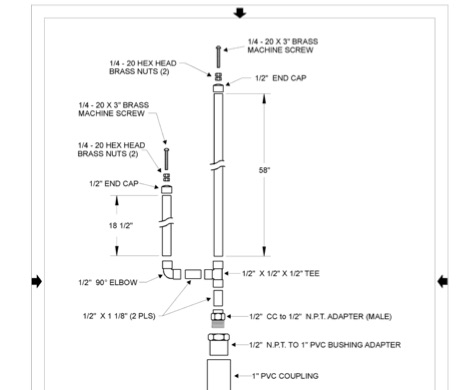 Complete plan for making a 2-meter J-Pole antenna. This drawing in PDF File includes a detailed list of the parts needed to assemble the Jpole antenna for 144 MHz.
 -
 This article provides a detailed guide on how to build a no holes roof mount for ham radio antennas. The author shares their design that can hold 2 masts and offers tips on installation. The mount is versatile and can handle small 144 Mhz or 432 Mhz beams, as well as small verticals. With adjustable angles and spacing, the mount can be customized to fit different roof types. Additionally, the author suggests affordable options for obtaining Dish antenna mounts. Overall, this DIY project offers a cost-effective solution for ham radio operators looking to mount antennas on their roofs.
 -
 Experimental Long Boom Antennas - CP, LPDA, multiband with several NEC Files for 50MHz 144MHz 222 MHz 432MHz but also 902MHz and 1296 MHz Antenna projects. Includes also for each antenna model, in a general comparison table each antenna characteristics including Directive Gain, G/T, E-F/R, H-F/R abd Boom Length. This is a great value comparison table of several commercial and home made VHF UHF antenna projects.
 -
 A Lightweight 2m Yagi for SOTA. The boom is 20mm PVC electrical conduit and the elements are 2.4mm aluminium TIG welding rod. The antenna is carried as a single length of conduit with the elements stowed inside the boom, sealing them in with a bung. The driven element is connected directly to 50 Ohm coax with a BN-43-202 balun core to decouple the coax shield.
 -
 This stacking offers a well known simple phasing technique. All elements can be fed in parallel by open wires provided that they are fed in phase. This can be achieved by twisting the open wire phasing-lines at 180 degrees.
 -
 A homebrew 13 elements yagi antenna for two meters band. These project includes two model of the same antenna with a 6 and 7 meter boom length. Detailed pictures and nec files are available for download
 -
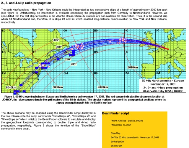 Thunderstorm effects on sporadic E propagation, Very long distance propagation in the 144 MHz band, Analysing the number of skips in multiple hop propagation
 -
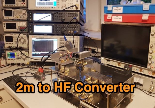 Ulrich L. Rohde N1UL conceived an outstanding 2m to HF receiving converter with specific requirements, including 144-148MHz to 28-32MHz coverage, low noise, high IP3, and a unique modular design. The design decisions emphasize modularity, absence of preselection, stability, and a passive mixer, showcasing Rohde's distinctive approach.
 -
 This project introduces the Loggi, a hybrid antenna merging the wide frequency coverage of log-periodic dipole arrays (LPDA) with the high gain and front-to-back ratio (F/B) of Yagi antennas. Traditional LPDAs span broad frequencies with moderate gain and low VSWR, while Yagis provide high gain and F/B over narrow bands. By analyzing high-Tau LPDA designs, it was found they could nearly match the gain of VHF/UHF Yagis while maintaining excellent patterns, F/B, and front-to-rear ratios (F/R). Optimizing specific elements for target frequencies (e.g., 144.1 MHz) led to the Loggi, which uniquely features all driven elements without passive directors or reflectors. This design effectively functions as a narrowband optimized LPDA, with front elements acting like Yagi directors and rear elements like Yagi reflectors, thus enhancing gain and directional characteristics while retaining broad frequency versatility.
 -
 A home made project for a 7 element yagi antenna for the two meters band based on the DK7ZB original desing.
 -
 The article describes a high-gain, compact beam antenna design for the 2-meter band (144-146 MHz). The NSH 4x4 Boomer is a 4-element antenna that is mounted on a 4-foot boom with an 8.2 dB gain, 1.2:1 SWR, and a front-to-back ratio of 18 db. It is designed for mobile operations and little area, making it perfect for field usage such as disaster management. The design employs regularly spaced parts with a straightforward gamma match for tuning, and the construction materials include a square boom and polished aluminum tubes. In local and portable tests, the antenna worked regularly, achieving contact distances of up to 15 kilometers.
 -
 A detailed guide presents a simple 2-element quad antenna for 2m, offering ease of construction, portability, and efficient performance across the 144-148 MHz band. The design allows quick disassembly for storage and features adjustable polarization, making it ideal for various applications, including transmitter hunting and SSB operations.
 -
 Discover the secrets of Six Meters with this comprehensive eBook by Jim Wilson, K5ND. Learn about the magic of 6-meter DXing, including propagation, antennas, equipment, operating software, and more. Whether you're a beginner or an experienced ham radio operator, this book covers everything you need to know. With over 8,000 downloads, this updated version includes new chapters on FT8/FT4, MSK144, and Q65 modes, as well as contesting, rover operation, and awards. Get your hands on this valuable resource and enhance your 6-meter DXing experience today.
 -
 Effective suppression of harmonics and parasitic radiation from HF transmitters is crucial, especially with the increasing sensitivity of VHF/UHF radio channels to interference. This project details a hybrid low-pass filter (LPF) designed to operate across the HF bands up to 51 MHz, making it suitable for 6-meter band operations while providing deep VHF/UHF suppression. The design addresses the challenge of modern interference landscapes, where even microvolt-level signals can disrupt wireless sensors and other simple VHF/UHF receivers. The filter utilizes a single elliptic link, combining high cutoff steepness with robust suppression in the hundreds of megahertz range. A key feature is the use of only two standard capacitor values, simplifying construction and component sourcing. The article provides a detailed schematic, performance characteristics, and _RFSim99_ model file, demonstrating a reflection coefficient S11 below 0.017 (VSWR < 1.03) across 1-51 MHz, ensuring minimal degradation to the antenna system. Construction notes include coil winding specifications and capacitor selection guidance, with recommendations for _FR-4_ assembly. Two capacitor sets are presented, with the first variant recommended for its lower RF current demands, keeping currents below 3 A at 1 kW passing power at 51 MHz. Fine-tuning involves adjusting frameless coils, with considerations for capacitor tolerance and high-frequency capacitance measurement accuracy.
 -
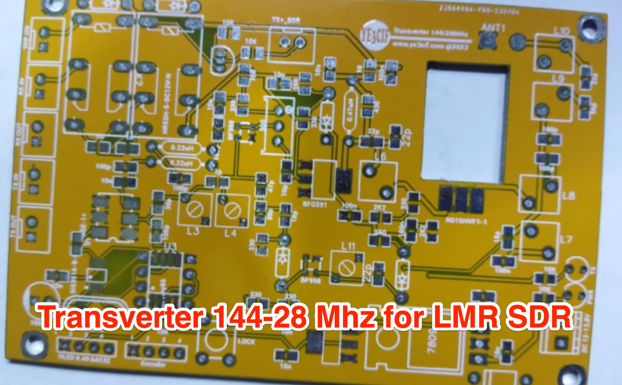 Learn how to build a VHF 144MHz transverter connected to an LMR SDR radio using easily accessible components. The transverter works by mixing the 144Mhz input frequency with a 116 MHz local oscillator frequency. Explore the challenges of finding a 116 MHz crystal and the solution of using a programmable Si5351A oscillator. Follow the provided schematic for the RX and TX sections. The transverter design is still a work in progress, with ongoing trials to achieve optimal results.
 -
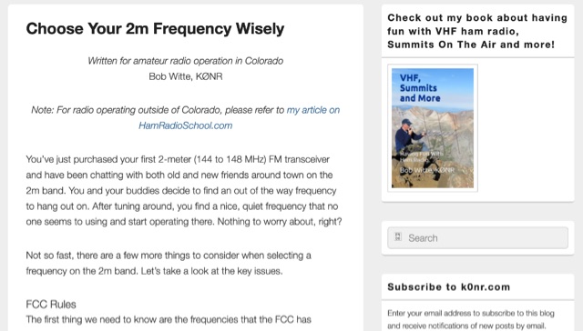 When new to the 2-meter FM transceiver, securing a quiet frequency for chatter seems straightforward, but it's essential to navigate FCC rules and band plans effectively. Even though frequency allocations are consistent above 50 MHz for Technician licenses, adherence to specific segments within the 2m band—ranging from 144 MHz to 148 MHz—is crucial. This includes respecting designations for different modes like CW, SSB, and FM to prevent interference, particularly with satellites and exotic modes like EME. Understanding and following the structured band plans not only ensures legal compliance but also optimizes frequency use and minimizes disruptions in the amateur radio community.
 -
 An FT-817 ceased transmission on the VHF 2m band, despite the other HF, UHF, and 50 MHz bands operating correctly. Suspecting an excess of input signal during FT-8 mode transmission, they conducted measurements with an oscilloscope, revealing a burnt-out PIN diode, identified as D3003, type HSU277, on the PA unit board. Following the replacement of this surface-mounted diode, their FT-817 resumed operation on the 144 MHz band.
 -
 This paper by Leif Asbrink (SM 5 BSZ) presents a practical approach to designing very high gain Yagi antennas, focusing on the "brute force" optimization method. The method, described in a previous article, ensures convergence independent of initial guesses. The paper provides detailed tables of element lengths and positions for Yagi antennas optimized for 144.1 MHz with a 50-ohm feed point impedance, aiming for minimal losses and high accuracy in comparisons.
 -
 The article discusses the construction of a UHF band-stop stub filter to protect an APRS receiver from potential damage during a balloon launch. The author, who communicates using a 441 MHz transmitter, needed to ensure that the RTL-SDR dongle receiving at 144 MHz wouldn't be damaged by the transmissions. The solution involved creating a quarter-wavelength open stub filter using coaxial cable, which attenuates the 441 MHz signal while allowing the 144 MHz signal to pass through. The filter's design is based on the principles of constructive and destructive interference, with careful measurement and trimming to achieve the desired frequency response. The final filter provided 34.8 dB of insertion loss at 441 MHz and minimal loss at 144 MHz, effectively protecting the receiver.
 -
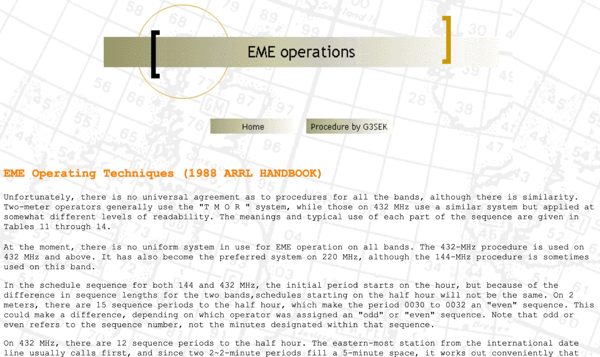 This resource provides an in-depth look at Earth-Moon-Earth (EME) operating techniques specifically for the 432 MHz band and above. It outlines the differences in operational procedures between the 144 MHz and 432 MHz bands, emphasizing the importance of sequence lengths and scheduling. The initial calling period typically starts on the hour, with the eastern-most station calling first, which is crucial for effective communication. The document also discusses the challenges faced by operators, such as signal readability and the necessity of confirming exchanges. It highlights the significance of using a standardized procedure to enhance the likelihood of successful contacts. Additionally, it covers the use of signal reports and the importance of patience and clarity in communication, especially when dealing with weak signals. Overall, this guide serves as a valuable resource for amateur radio operators interested in improving their EME operations.
 -
 The project aims to create a remote control system for the VK5RSE beacons located near Millicent, South Australia. The beacons on 144.550, 432.550, and 1296.550 MHz can interfere with nearby amateur radio operations, particularly for EME work on 1296 MHz. The remote control system uses a DTMF decoder and PIC microcontroller to allow turning the beacons on and off individually or in combination. The system is housed in a diecast box and powered from 5-8V. The password-protected control allows authorized users to manage the beacon operations remotely, helping mitigate interference issues for local amateurs.
 -
 Details the Virtual COM Port (VCP) drivers for Silicon Labs CP210x USB to UART Bridge devices, which are crucial for establishing serial communication between a host system and CP210x-based hardware. It covers driver availability for Windows, macOS, Linux, and Android, highlighting the necessity of these drivers for operating CP210x products as a virtual COM port. The resource also mentions the option for direct access drivers and references _Application Note 197_ for comprehensive serial communication guidance. The page specifies that the CP210x Manufacturing DLL and Runtime DLL have been updated, requiring their use with v6.0 and later of the Windows VCP Driver, impacting specific application note software downloads like AN144SW.zip. It notes that Linux 3.x.x and 4.x.x driver versions are maintained within the _Linux kernel tree_ at www.kernel.org, ensuring ongoing support. Legacy OS software is also provided for users requiring support for 5.x drivers, ensuring broad compatibility.