Search results
Query: low bandwidth
Links: 72 | Categories: 0
-
 AN-SOF is a professional comprehensive software tool for the modeling and simulation of antenna systems. AS-SOF allows to describe antenna geometry, Choose construction materials, Describe the environment and ground conditions, Describe the antenna height above ground, Analize radiation pattern and front-to-back ratio, Plot directivity and gain, Analize input impedance and VSWR,Predict antenna bandwidth
-
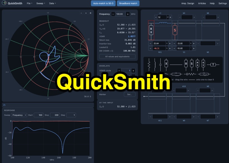 QuickSmith provides an online _Smith chart_ for impedance matching, enabling users to drag virtual components onto a ladder network and observe dynamic trace movement. The tool displays live readouts for critical parameters such as VSWR, return loss, insertion loss, loaded Q, and bandwidth. It facilitates auto-matching to **50 ohms** with various network choices and supports _Touchstone_ file import, allowing _NanoVNA_ measurements to be plotted directly for analysis. Beyond basic matching, QuickSmith includes features for frequency and component sweeps, generating S11 and S21 response graphs. It also supports amplifier design, incorporating stability, gain, and noise circles, alongside microstrip and coax synthesis capabilities. The platform offers shareable links, worked examples, and guided tours, making it a practical resource for hams learning about RF circuit analysis and antenna optimization.
-
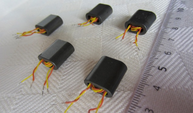 Operating within the low-frequency spectrum, transformers serve critical roles in antenna systems, particularly for 160m applications. The resource details the construction and performance of 1:1 transformers built on BN-73-202 cores, emphasizing their use as hybrid combiners or phase inverters for RX antenna arrays. Measurements reveal that these transformers exhibit minimal losses, around 0.12 dB at 1.8 MHz, with variations based on wire type and number of turns. The analysis includes comparative data on transformer performance, highlighting the impact of different winding techniques on frequency response. Notably, the use of coaxial cable for winding improves bandwidth while maintaining low-frequency efficiency. The resource also discusses braid breaker transformers, which minimize inter-winding capacitance, achieving low losses around 0.21 dB at 1.8 MHz. These insights are crucial for optimizing low-band antenna systems, allowing operators to make informed decisions regarding transformer design and implementation.
-
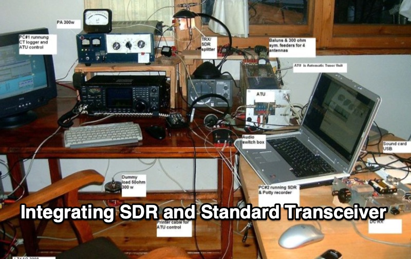 Integrating a _Software Defined Radio_ (SDR) into an existing ham radio setup involves connecting it with a standard transceiver (TRX), power amplifier (PA), and antennas. The core component is a splitter box that facilitates the connection between the TRX and the SDR, allowing for simultaneous operation without modifying existing equipment. In receive mode, the splitter ties the antenna inputs of both the TRX and a direct conversion receiver (DC RX) together. During transmission, the DC RX input is grounded via a fast telecom relay controlled by the transceiver's -SEND signal, incorporating a 10ms delay for safety. The splitter box includes a 3.7 dB input attenuator for impedance matching and acts as a protective fuse for the DC RX input. Ground loops are mitigated using common mode balun transformers, while the DC RX input is insulated with a broadband transformer. An audio switch box complements the setup, enabling users to listen to either the main transceiver, the SDR output, or both simultaneously. This configuration ensures noise immunity and safety, with the splitter housed in a screened box made from PCB material. On-air tests, such as the CQ WW 160m CW DX Contest, demonstrate the system's effectiveness, showcasing the SDR's ability to handle crowded band conditions with superior selectivity and dynamic range. The SDR's narrow bandwidth filters and waterfall display provide significant advantages, allowing operators to detect weak signals amidst strong interference. The integration of SDR with conventional radios offers enhanced operational flexibility and performance in challenging environments.
-
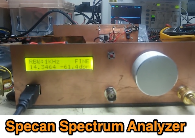 A homebrew spectrum analyzer, the Specan, provides a crucial measurement capability often missing from the typical amateur radio shack, allowing for detailed analysis of RF signals up to 70 MHz. This double-conversion superheterodyne receiver design incorporates 112 MHz and 12 MHz intermediate frequencies, utilizing an _Si570_ as the local oscillator for fine tuning down to 1 Hz steps. It offers two resolution bandwidths: 300 KHz for broad spectrum sweeps and 1 KHz for precise close-in distortion measurements, achieving an 80 dB spur-free dynamic range at 1 KHz resolution. The project, a reboot of the classic _W7ZOI/K7TAU_ design from November 1998 QST, integrates an _Arduino_ microcontroller for controlling the Si570, managing a front-panel LCD, and communicating with a PC for spectrum plotting. This approach significantly reduces cost compared to commercial units, making advanced RF diagnostics accessible to homebrewers. The Specan can measure carrier suppression, VFO cleanliness, antenna VSWR, transmitter harmonics, and filter passband shapes, providing insights beyond what an oscilloscope or frequency counter can offer. Construction emphasizes modularity and careful shielding, with each stage built and tested individually on unetched copper clad board. The design includes detailed instructions for integrating the Arduino, building the Si570 oscillator, and aligning the various modules, often using the Specan itself for calibration. It requires a well-regulated linear power supply and can be built with common tools and readily available components, making it a practical and rewarding endeavor for those looking to enhance their RF test bench.
-
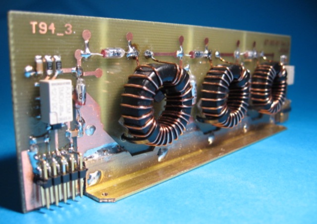 This article explores the nuanced design challenges of Band Pass Filters (BPF) in radio receivers, balancing low insertion loss, high stop band rejection, and narrow bandwidth. The focus is on the "Series-Trap, Shunt-C" topology, resonator count impact, and meticulous layout design for superior stop band performance across various frequency bands
-
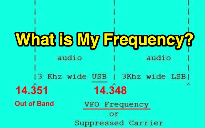 Single Sideband (SSB) operation requires careful attention to the relationship between a radio's displayed frequency (suppressed carrier) and the actual 3 kHz wide audio signal. This resource clarifies how Upper Sideband (USB) and Lower Sideband (LSB) signals occupy spectrum above or below the indicated frequency, respectively. It provides practical examples for General Class operators on the **20m** and **40m** bands, such as setting a VFO to 14.226 MHz for USB on 20m or 7.178 MHz for LSB on 40m, to maintain a safe margin from band edges. The resource emphasizes the critical importance of staying within allocated band limits to prevent out-of-band emissions, particularly when operating close to band edges. It includes relevant excerpts from **FCC Regulation Part 97**, specifically section 97.307, which details emission standards, necessary bandwidth, and spurious emission attenuation requirements. The text explains that unused sidebands are considered spurious emissions and notes that modern HF equipment typically exceeds the 43 dB spurious emission reduction standard, often achieving 60 dB or more.
-
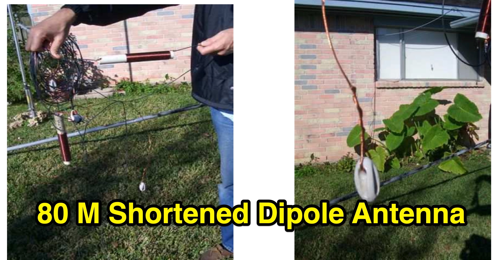 The LKJ Wednesday Night Special Antenna, designed by John Whiteman K5LKJ, is a compact 50-foot coil-loaded dipole for 80-meter operation, ideal for space-limited hams in residential areas. Using two 1-inch diameter PVC coils with 87 turns of #16 magnet wire each—placed 10 feet from the center—it tunes to 3.910 MHz for local nets like BVARC Rag Chew. Constructed with #14 wire, ceramic insulators, and Mini-8X feedline, it handles 1000W, performs well at low heights for NVIS, and requires a tuner for bandwidth. Collaborative tuning by club members ensured success.
-
 This document provides comprehensive guidance on modeling and constructing multiband dipole antennas using traps. It addresses common segmentation issues in EZNEC modeling software, recommends optimal segment lengths for trap models, and compares trapped dipoles with paralleled multiband dipoles. While trap dipoles are significantly shorter, they exhibit lower gain and narrower bandwidth. Detailed instructions for building weatherproof coaxial traps include material lists, construction steps, and tuning methods. The guide notes that properly constructed coaxial traps introduce only minimal signal loss (0.6 dB) while offering practical multiband performance in a compact design.
-
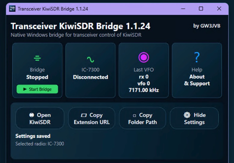 Demonstrates a practical solution for remote reception, the Transceiver-KiwiSDR Bridge, a free Windows utility by GW3JVB. This software links a local amateur radio transceiver to a remote **KiwiSDR** receiver, allowing the KiwiSDR to automatically track the transceiver's VFO frequency and mode. This capability proves invaluable for mitigating local noise, enhancing reception, or simply leveraging the superior receive capabilities of a remote station located globally. The bridge supports a diverse range of transceivers through COM port/CAT connections or **TCI** over a network. Specific compatibility extends to popular models like the Icom IC-7300, systems utilizing the TCI Protocol (such as Thetis, Expert Electronics, Apache Labs ANAN, and Hermes Lite 2), and many radios supported by Hamlib. Experimental Yaesu CAT options are also included, broadening its utility for various shack configurations. Key features encompass automatic mode changes, updates to RX filter bandwidth, and even IC-7300 PBT/filter adjustments. The application integrates a browser extension for Chrome, Brave, and Microsoft Edge, and offers an optional KiwiSDR audio mute during local transmission, ensuring a seamless operating experience. The compact view keeps the interface unobtrusive, with full settings readily accessible.
-
 This software enables remote monitoring of the Kenwood TS-590SG HF transceiver. Based on a lightweight, text-based monitor was developed using Python and ncurses. It connects via rigctld, displaying key metrics like frequency, power, SWR, and TX/RX state with minimal data usage. Ideal for low-bandwidth remote operation, it works over SSH or mobile data. The software is open-source under GPL v3.
-
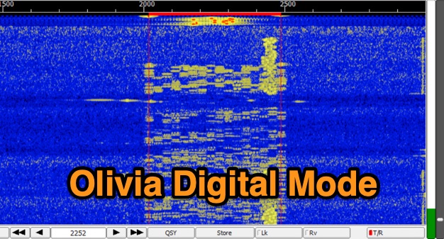 The Olivia digital mode, a **Multi-Frequency Shift Keying (MFSK)** radioteletype protocol, is specifically engineered for robust communication under difficult propagation conditions on shortwave radio bands from 3 MHz to 30 MHz. Developed by Pawel Jalocha in 2003, Olivia signals can be decoded even when the noise amplitude exceeds the digital signal by over ten times, making it highly effective for transmitting ASCII characters across noisy channels with significant fading and propagation phasing. Early on-the-air tests by Fred OH/DK4ZC and Les VK2DSG on the Europe-Australia 20-meter path demonstrated intercontinental contacts with as little as one-watt RF power under favorable conditions. Common Olivia modes are designated as X/Y, where X represents the number of tones and Y is the bandwidth in Hertz, with examples including 8/250, 16/500, and 32/1000. The resource clarifies that Olivia, unlike some other digital modes, produces a constant envelope, allowing RF power amplifiers to achieve greater conversion efficiencies and making it less prone to non-linearity. Operators are advised that **Automatic Level Control (ALC)** can be set higher than no meter movement for MFSK modulation, as long as it's not driven past its high limit, contrary to common misinformation about other digital modes. The Olivia community encourages voluntary channelization on suggested calling frequencies, such as 14.0725 MHz for 8/250, to facilitate initial contacts, especially for signals below the noise floor. The Olivia Digital DXers Club provides links to Groups.io, Facebook, and Discord for community engagement and offers details on QSO parties.
-
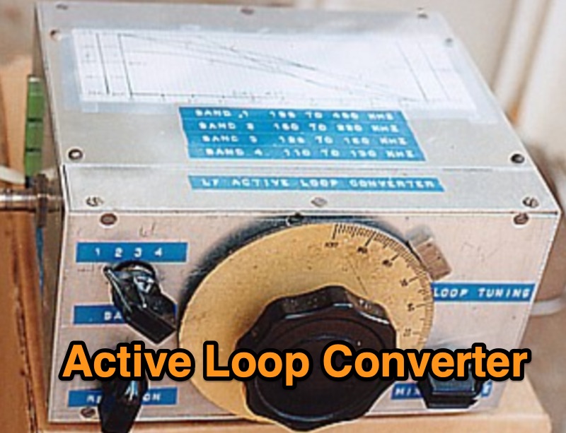 Demonstrates the construction of an active loop converter specifically designed for the Low Frequency (LF) bands, addressing common localized noise interference in LF reception. The design integrates a sharply tuned circuit and a tuned loop antenna, utilizing the loop as the sole tuned inductive element. By applying positive feedback, the converter significantly increases the loop's effective Q, achieving factors between 1000 and 2000, which sharpens tuning and reduces noise. The circuit employs an _NE602_ mixer stage, feeding its output to an HF receiver, with a crystal-locked local oscillator at 4 MHz. A 20-turn, 0.8-meter square loop antenna with 500 uH inductance is detailed, connected via 2 meters of figure 8 flex cable. The converter offers three selectable frequency bands: 195-490 kHz, 150-220 kHz (including the New Zealand amateur band), and 128-160 kHz (covering the European amateur band). Performance measurements indicate an effective 3dB bandwidth of approximately 100 to 200 hertz at 200 kHz. The article provides insights into component selection, including an _LF353_ op-amp and a trifilar wound transformer on a ferrite core. Sensitivity figures are presented, showing 7.5 uV of converted output per 1 uV/meter signal strength into a 50-ohm load, or 37.5 uV into an _FRG7_ receiver, highlighting its capability to extract weak signals from noise.
-
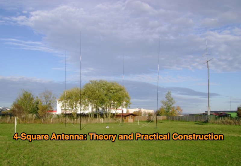 DF6QV's 4-Square antenna analysis begins with a two-element array simulation, demonstrating azimuth and elevation plots for various phase differences, including a 75-135 degree range. The document then delves into the core components of a 4-Square system, such as radiators, couplers, phasing lines, and ground systems, referencing W1HKK's 1965 QST article on an 80m phased array. It explores the influence of ground conditions and element spacing on antenna performance, presenting EZNEC analysis for an 80m 4-Square with an elevated radial, showing how gain and beamwidth vary with spacing. Various 90-degree couplers, including the 3 dB hybrid coupler and the Reed Fisher coupler, are analyzed using LTSpice, detailing power splitting, phasing, and bandwidth characteristics. The resource quantifies power, voltage, current, and losses within a 4-Square system, addressing relays, capacitors, inductors, radiator radial systems, and cable losses. System impedance, bandwidth, SWR, isolation, and mutual coupling are discussed with practical construction aspects covering common mode chokes, phasing boxes, and remote control systems. Field test observations for 40m 4-Square antennas are included, with specific examples from DXpedition operations like 5A7A and VP6DX, providing real-world context to the theoretical and simulated results.
-
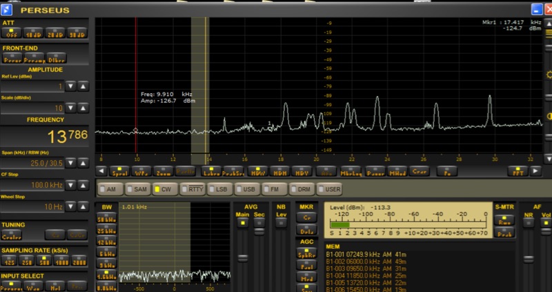 Investigates the performance characteristics of the _AAA-1_ active loop antenna across Very Low Frequency (VLF) and Low Frequency (LF) bands. It details the antenna's frequency response, explaining how a small loop with a low input resistance trans-impedance amplifier maintains a flat frequency response to electromagnetic field intensity E. The document illustrates current source and Thevenen equivalent circuit models for small loops, emphasizing the transition between these models based on frequency and load impedance. Measurement setups for both high frequency and VLF/LF responses are presented with diagrams, including methods for simulating current and voltage sources. The analysis includes normalized plots of the _AAA-1_'s frequency response for three distinct loop inductances, derived from measurements using a _Perseus SDR_ at 1 kHz bandwidth. It provides calculations for the noise floor at VLF/LF frequencies, comparing ambient noise levels with the antenna's internal noise floor. The resource also documents practical reception experiments in a semi-urban environment, showcasing successful reception of time transmitters like _MSF_ at 60 KHz and _SAQ_ at 17.2 KHz, along with various navy digital transmissions and Russian Alfa beacons.
-
 DXLog.net Cluster functions as a dedicated client application designed to enhance DXLog.net contest logging operations. It facilitates simultaneous connections to multiple DX cluster nodes, providing a consolidated view of DX spots. The software also supports integration with local CW skimmers, enabling real-time reception of CW signals and their automatic decoding into spots. The utility broadcasts UDP data across the local area network, allowing DXLog.net to receive and process these spots efficiently. A key feature includes CAT control integration, which automatically QSYs connected CW skimmers to the frequency of interest, optimizing spot acquisition. The system also incorporates duplicate spot filtering to reduce redundancy and offers blacklist management for unwanted callsigns or frequencies. Programmable commands and dynamic skimmer bandwidth control further refine its operation, adapting to varying band conditions and contest strategies. Automatic reconnection capabilities ensure continuous operation, maintaining reliable access to DX information crucial for competitive contesting.
-
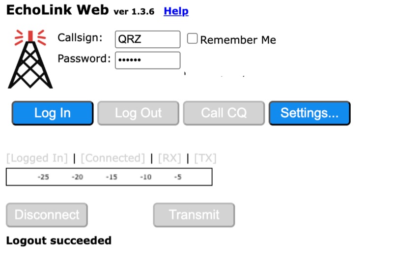 Connecting to the global *EchoLink* network via a web browser simplifies internet linking for licensed amateur radio operators. This web application provides a direct interface, eliminating the need for client software installation. Users can log in with their validated callsign and password to access the system, facilitating contacts with other stations, repeaters, and conferences worldwide, much like traditional VoIP applications but tailored for amateur radio. The interface offers essential controls for managing connections, including selecting specific stations or conferences from a dropdown list, initiating a connection, and disconnecting. Features such as a 'Call CQ' button allow users to signal their availability for a contact, while options for low bandwidth operation and accepting incoming connections optimize performance and accessibility. Audio device selection ensures proper microphone and speaker integration with the web client. Validation of an amateur radio license is a prerequisite for full access, ensuring that only authorized operators utilize the network. The system prompts unvalidated users to provide an email address and password to begin the validation process, which typically involves submitting proof of license. This free service extends the reach of amateur radio communications globally, bridging geographical distances through internet connectivity.
-
 This article describes the implementation and testing of a low-power GPS tracker using LoRa technology in the 433MHz amateur band. The system, built with AIThinker RA-02 modules and Arduino controllers, demonstrated successful communication over non-line-of-sight distances up to 5km. Operating with a 125kHz bandwidth and spreading factor of 11, the tracker achieves a data rate of 500 bits/sec. Powered by a LiPo cell with power-saving features, the final compact design operates for approximately 1.5 weeks between charges with 3-minute reporting intervals, consuming just over 1mA in idle mode.
-
 Demonstrates _FreeDV RADE_, an open-source digital voice mode for HF, which combines machine learning with classical Digital Signal Processing (DSP) to achieve improved speech quality and spectral efficiency. Released in June 2025 by ARDC grantee FreeDV, RADE operates at Signal-to-Noise Ratios (SNRs) as low as -2 dB and occupies approximately 1.5 kHz of bandwidth, half that of a typical SSB signal, while transmitting about 8 kHz of voice audio. The mode also features an optimized Peak-to-Average Power Ratio (PAPR) for efficient power amplifier use, reducing heat and consumption. Users, such as _VK3TPM_, report significantly improved listening ease compared to analog modes, particularly in high HF noise environments, making it easier to conduct nets across various Australian states. The mode's integration into popular radios like the _FlexRadio 6000_ series allows direct operation without external computers. A C library for RADE is available, facilitating broader integration into other radios and SDR programs, with development continuing on FreeDV RADE v2 to further narrow bandwidth below 1 kHz.
-
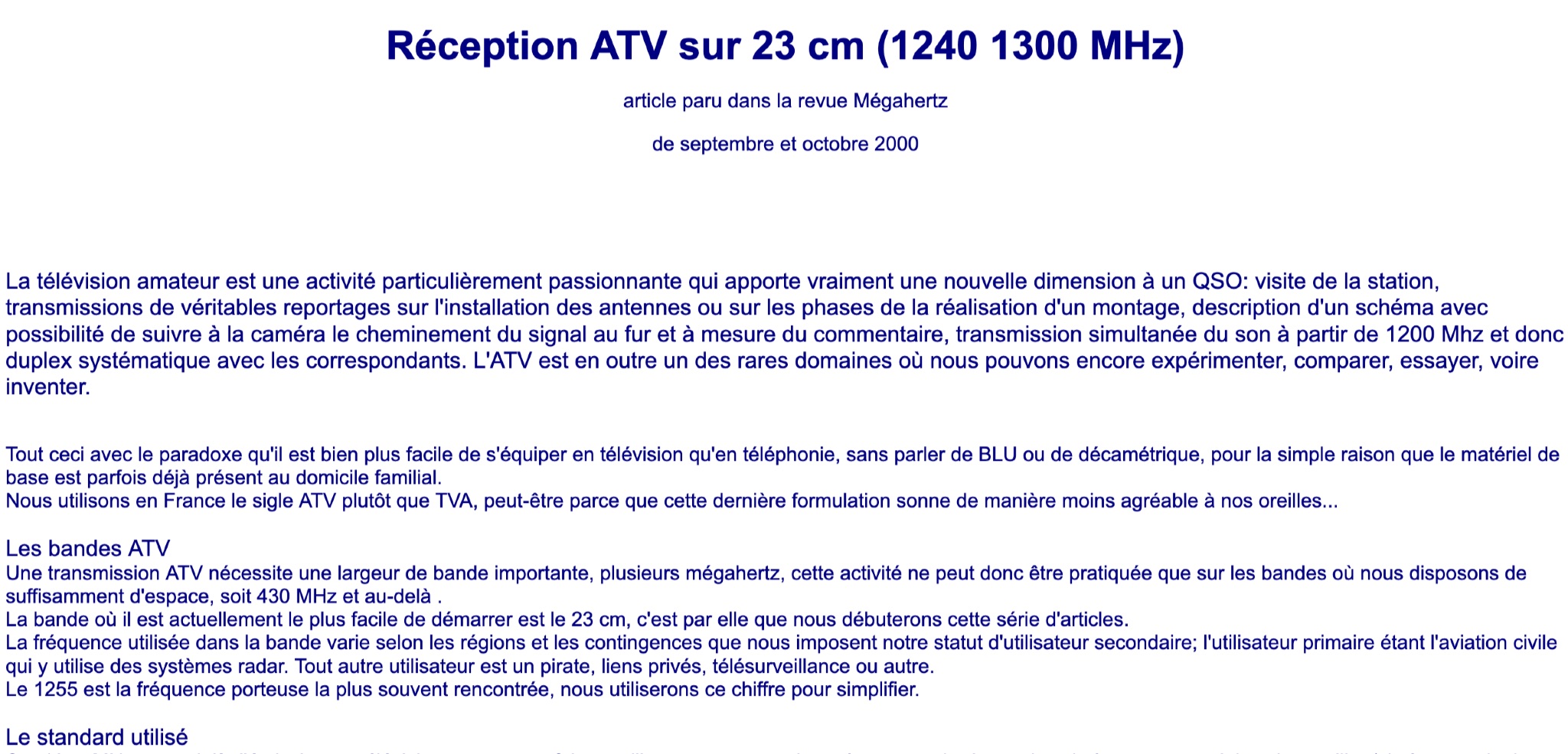 Learn about Amateur Television (ATV) on the 23 cm band (1240-1300 MHz) in this article from the September and October 2000 issue of Mégahertz magazine. Discover how ATV adds a new dimension to QSOs by allowing hams to visit stations, transmit real reports on antenna installations, follow signal paths on camera, and have simultaneous sound transmission. Explore the world of ATV experimentation, comparison, and innovation, made easier by existing equipment in many ham radio operators' homes. Find out about the ATV bands, bandwidth requirements, and the 23 cm band as a starting point for ATV activities.
-
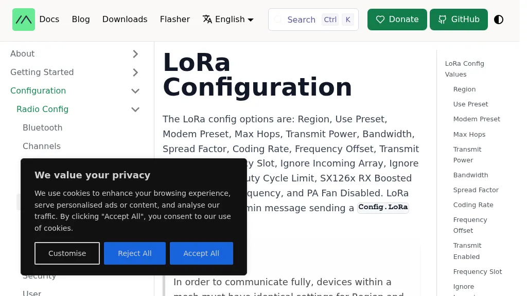 The Meshtastic documentation outlines critical LoRa configuration parameters for node operation, emphasizing regulatory compliance. It details settings such as Region, Modem Preset, Max Hops, Transmit Power, Bandwidth, Spread Factor, Coding Rate, and Frequency Offset. A comprehensive table provides region codes, frequency ranges (e.g., US **902.0 - 928.0 MHz**), duty cycles, and power limits (e.g., EU_433 **12 dBm**) for numerous countries, including the US, EU, China, and Japan, alongside a 2.4 GHz band option. It explicitly states that devices within a mesh must share identical _Region_ and _Modem Preset_ settings for full communication. Modem Presets, like _LONG_FAST_ (the default), optimize for either speed or range, directly impacting network congestion and message delivery delay. For instance, SHORT_TURBO offers the fastest speed and shortest range, while VERY_LONG_SLOW provides the longest range but is less reliable for mesh formation. The document also highlights specific duty cycle limitations, such as the 10% hourly limit for EU_433 and EU_868 regions, and provides command-line interface (CLI) examples for configuring these parameters.
-
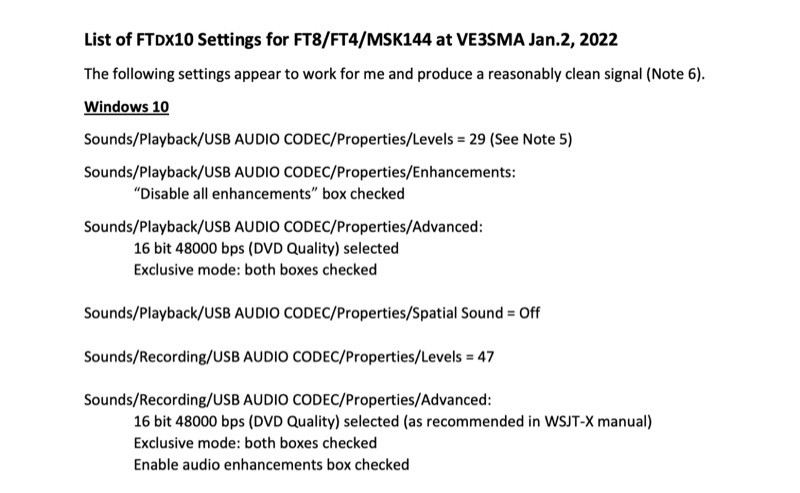 Configuring a Yaesu FTDX10 transceiver for digital modes like FT8, FT4, and MSK144 requires precise adjustments across both the operating system and the digital mode software. This resource details specific Windows 10 audio codec settings, including playback levels at 29 and recording levels at 47, along with advanced 16-bit 48000 bps (DVD Quality) selections for optimal signal fidelity. It also specifies checking the "Disable all enhancements" box for playback and enabling audio enhancements for recording. The document outlines critical WSJT-X v.2.5.1 parameters, such as setting the Rig to FTDX-10, a 1-second poll interval, and a 38400 baud rate for CAT control. The PTT method is configured to RTS, with Split Operation set to "Fake It" or "None." Audio input and output are directed to the USB AUDIO CODEC, with a recommended WSJT-X Pwr Slider setting of -32.0 dB, adjusted to ensure ALC meter readings remain within the white segment on the FTDX10. Transceiver-specific settings include a CAT RATE of 38400 bps, AMC RELEASE TIME set to MID, and DATA SHIFT (SSB) at 1500 Hz. The RPORT GAIN is specified at 70, with notes suggesting lower values (e.g., 30) can also yield clean signals. Transmit bandwidth selection is discussed, recommending 50-3050Hz for wideband modes like MSK144, while suggesting 400-2600Hz for FT4/FT8 to mitigate second harmonics and improve signal purity. The guide also references discussions with W5AJ, DO1YHD, AC6BW, and W9RTB.