Search results
Query: nec antenna
Links: 353 | Categories: 2
-
 Antennas, books, rf parts, tubes,connectors and cables and many accessories at RF parts.
 -
 Manufacturer of communications antennas, bandpass filters, RF combiners, receiver multicouplers, diplexers, duplexers, RF connectors, RF circulators, RF isolators, RF couplers and SWR meters
 -
 Build parabolic WLAN antenna adapted from a small satellite dish. It provides high gain and long range connections.
 -
 Technical reference about Accessories, Amplifiers, Antennas, Cable and Connectors, Filters, Geography, Grounding, Gunk, Matching Networks, Projects, Propagation Info Radios, RFI/EMI, Rotors, Station Setup, Towers.
 -
 Constructing a **2-meter** J-pole antenna from readily available copper plumbing components offers a robust and cost-effective solution for VHF operation. This design, dubbed the "Plumber's Delight," functions essentially as a half-wave dipole fed by 50-ohm coax via a **gamma match**. It incorporates a quarter-wave copper tubing support, which, when affixed to a metal mast or tower, enhances forward power in the direction of the radiating elements. The original configuration utilized a small ceramic trimmer capacitor for the gamma match, suitable for up to 10 watts. A subsequent modification replaced this with a 50 pF variable capacitor housed in a plastic enclosure, accommodating higher RF power and improving weather resistance. The antenna elements are secured using a copper "T" fitting, and an SO-239 connector mounts directly to this fitting. Performance includes gain away from the support mast, and tuning is straightforward by adjusting the gamma match capacitor for a 1:1 SWR. The total cost for materials, excluding the capacitor and coax, can be under $10.
 -
 The BV6 50 MHz Yagis resource details the construction of two distinct Yagi antenna designs for the 6-meter band, specifically a 1-wavelength (1wl) model and a 2.1-wavelength (2.1wl) model. The 1wl Yagi, with a boom length of 5.850m, achieves a gain of **9.4 dBd**, while the 2.1wl Yagi, spanning 12.90m, boasts a gain of **11.9 dBd**. These designs adhere to a proven methodology for optimizing current slope and maintaining constant phase delay across parasitic elements, ensuring high gain per boom length and an _excellent pattern_. Both designs target a 50-ohm input impedance, facilitating straightforward feeding with a robust folded dipole. Final verification using NEC-II software confirmed the antennas' exceptional stacking capabilities, yielding stacking gains exceeding **5.8 dB** for a 2x2 array with minimal mutual detuning. The resource provides common mechanical data, including boom and element diameters, and specifies element lengths corrected for boom diameter. While the original _DUBUS Technik V_ publication contained incorrect element lengths, this resource provides the accurate dimensions for proper construction, emphasizing the use of readily available materials for cost-effective amateur radio deployment.
 -
 A 40-meter reversible _Moxon rectangle_ antenna project details its construction and performance, featuring 51-foot long sides and 7.7-foot turned-in sections. The design incorporates a 16.5-foot boom, with elements spaced 1.1 feet apart, constructed from #14 covered wire. It utilizes two double-pole relays for switching between NE and SW directions, achieving F/B ratios up to 40 dB on CW and 30 dB on SSB, with distinct reflector stub settings for each mode. This antenna replaced a full-size 2-element Yagi, demonstrating comparable forward gain while offering superior F/B ratios and directional flexibility. _EZNEC_ modeling indicates only 0.2 dB less forward gain than the Yagi. The system uses no baluns, relying on half-wave feedlines and switched stubs for impedance matching. The antenna is tree-supported at 45 feet, with its effective radiation height modeled at 80 feet due to local terrain, enhancing its performance over a nearby lake.
 -
 Autotena, a Taiwanese manufacturer, offers a diverse product line focused on RF communication antennas and related accessories. The resource details various antenna types, including **4G/3G LTE wideband high-gain low-profile antennas**, land mobile wideband antennas, fiberglass omnidirectional designs, and GPS mobile and marine antennas. Specific amateur radio offerings include NMO VHF load coil gain antennas, VHF whip gain antennas with PL-259 connectors, and UHF NMO mount antennas with 3dB/5dB gain. The company also produces antennas for CB and 10-meter amateur bands, such as aluminum broadband 26-30MHz antennas and big copper coil broadband 26-30MHz antennas. Additionally, the site showcases **RF amplifiers** for CB, HF, VHF, and UHF bands, including professional-grade base station amplifiers with 100% EIA duty cycle. Handheld antennas, PL-259 type mobile antennas, magnet mount antennas, and external CB speakers are also presented, alongside various mounting kits and cable assemblies.
 -
 End-Fed Half-Wave Antennas (EFHWAs) are analyzed for their utility in portable QRP operations, emphasizing their simplicity, efficiency, and predictable radiation patterns compared to other portable antenna types. The discussion contrasts EFHWAs with vertical antennas, random length wires, and center-fed dipoles, highlighting the common pitfalls of each, such as ground system dependency for verticals and feedline issues for dipoles. The article details the electrical half-wavelength calculation using the formula L (Ft) = 468/F(MHz) and explains how EFHWAs can be resonant on harmonic frequencies, enabling multiband operation. Various deployment configurations are presented, including the inverted L, inverted Vee, sloping wire, and vertical setups, each with specific advantages for radiation angle and polarization. For instance, a vertical EFHWA offers a low angle of radiation suitable for DX contacts without requiring an extensive ground system. The resource also addresses the counterpoise requirements, suggesting a quarter-wavelength wire or connection to a metallic structure for decoupling. A schematic diagram for a simple parallel-tuned circuit tuner, based on the _Rainbow Bridge/Tuner_ design, is provided, detailing component values for 30 and 40 meters, including a 6 microhenry toroidal inductor and a 20-100 picofarad mica compression capacitor. The tuner's adjustment process for SWR matching is also outlined.
 -
 Over 75 years of engineering expertise underpins Bird Electronic's offerings in RF power measurement, critical for maintaining peak performance in amateur radio stations and professional communication systems. The company specializes in a range of test equipment, including wattmeters, SWR meters, and antenna analyzers, essential for optimizing antenna systems and ensuring efficient power transfer. Their product line extends to various RF components such as filters, cables, and connectors, all designed to meet stringent technical specifications for reliability and accuracy across diverse frequency bands. Bird Electronic's instruments, like the _Bird 43_ Thruline Wattmeter, are widely recognized for their robust construction and precise measurement capabilities, providing hams with confidence in their station's operational parameters. These tools enable accurate assessment of forward and reflected power, SWR, and modulation characteristics, which are vital for troubleshooting and maximizing radiated power. The company's commitment to innovation ensures that its products remain relevant for modern RF challenges, from HF through microwave applications, supporting both traditional analog and advanced digital modes.
 -
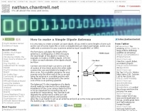 It is very easy to create a simple 1/2 wave dipole, all you need is some lengths of wire such as the core of some mains flex or even a straightened out metal coat hanger, some co-ax cable and a connector for your scanners antenna input
 -
 This PDF document, authored by KT4QW in October 2004, details the construction and modeling of a dual-band, horizontally polarized hanging rectangular loop antenna for **10 and 17 meters**. The design, adapted from *The ARRL Handbook*, utilizes _NEC4WIN95_ software for scaling and optimization, targeting a 50 ohm feedpoint impedance. The resource includes a bill of materials, step-by-step construction instructions, and a discussion of the antenna's radiation characteristics. It presents NEC-generated elevation and azimuth patterns, comparing the loop's performance to a half-wave horizontal dipole at the same height and frequency. The 17-meter element is centered at 18.140 MHz for low SWR across the phone band, while the 10-meter element is centered at 28.500 MHz. Construction involves 14-gauge stranded copper wire and Schedule 40 PVC spreaders, with the total wire length calculated by the formula: Length in feet = 1005/MHz. The feedpoint impedance can be adjusted by modifying the rectangular aspect ratio. The document specifies hoisting the antenna to at least a half-wave above ground for testing. It notes that a balun was tested and found to have no measurable effect on SWR or radiation characteristics. A 2-meter scale model is presented to illustrate the physical design, and a "rotator" string is incorporated for directional adjustment up to 90 degrees.
 -
 WorldRadio Article on Petlowany antennas base on this principle: if a length of wire is wound into a spiral-shaped coil and excited by a radio frequency current connected to the innermost portion of the coil, it will then, and only then, exhibit RF characteristics that closely approximate those of a resonant linear wire of the same length
 -
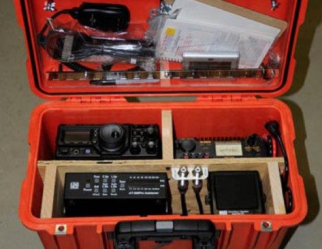 The best way to describe a go-box is a complete amateur radio station in a box. An example is described in this article. The project describes building a portable amateur (ham) radio station, known as a "go-box," housed in a durable orange Pelican case. The go-box contains all necessary radio equipment except for external power and antennae, which are carried separately. It includes items like a Yaesu transceiver, power supply, antenna tuner, speaker, and a clock. The case is designed for mobility and visibility, with a vertical layout to allow in-vehicle operation. Future upgrades might include cooling fans, an LED lamp, and built-in antennae for better functionality in various conditions.
 -
 Antenna data, and design note for this horizontal loop antenna resonating on 80 Meters by K0ZE
 -
 Antenna that's simple, inexpensive lightwiight and easy to install
 -
 Bill Orr W6SAI ham radio techniques. Improving ground connection, computer analysis of the antenna, modelling sample antennas pdf file
 -
 The document details the optimization and construction of the _Maria Maluca_ antenna, a compact 6-band (20m-6m) directional beam. It presents a comparative analysis of shortwave antenna principles, highlighting the efficiency gains achieved by using an open feeder line and tuner as a resonant unit, contrasting this with the losses associated with traps or capacitive loads in multiband antennas. The resource specifically revisits an older South American 2-element design for 10, 15, and 20 meters, applying modern NEC-based software to develop a six-band version. Performance data is meticulously tabulated, showing impedance, free space gain, gain at 12m height, elevation angle, and front-to-back (F/B) ratio for each band from 20m through 6m. For instance, on 15m, the antenna achieves 5.1 dBd free space gain and 13.72 dB F/B ratio. The construction section provides practical guidance on element assembly using aluminum pipes and hose clamps, detailing the use of a heavy-duty glass fiber reinforced polyamide rod for electrical separation and bending strength. It also specifies the use of 450-ohm _Wireman_ line CQ 552 for the transmission line. The document includes diagrams for rod fixing, an air-wound balun, and a vertical elevation diagram for the 15m band, illustrating its DX qualification. It also discusses the antenna's suitability for portable and expedition operations, noting its compact transport dimensions (max 1.50m length, 12 lb weight) and quick assembly time (under 15 minutes). The author, Dipl.Ing. Helmut Oeller, DC6NY, is identified as a source for material kits.
 -
 How slinky loaded beverage antennas works, includes eznec models
 -
 Constructing a compact, two-band magnetic loop antenna for HF operation, especially from constrained locations like a balcony, presents unique challenges. OK1FOU's design, inspired by DJ3RW's 50 MHz loop, addresses these by employing an unusual side-fed configuration and placing the symmetric, two-section variable tuning capacitor at the bottom of the loop, directly connected to the coax shield. The article provides specific material recommendations, including two 1-meter wooden pales and about 3 meters of thick loudspeaker cable, noting the high current (60A at 100W) in the loop. Construction steps detail forming two turns with a 5 cm gap, using a GDO to pre-tune the open loop to a frequency slightly above the desired highest band, and then integrating the tuning and coupling capacitors. For 10/14 MHz, an open loop resonance of 16-17 MHz is suggested. Practical experience with the 10 MHz band from a third-floor balcony in Prague (JO70GC) shows a 1:1 SWR across most of the band without an external ATU. While DX traffic was modest due to the urban environment, QSO examples with RA6WF, LA6GIA, G0NXA, and LZ1QK on 10 MHz are provided, demonstrating its operational capability.
 -
 Constructing a Lindenblad antenna for 137MHz NOAA satellite reception involves specific design considerations for optimal performance. The resource details the use of 4mm galvanised steel fencing wire, 300-ohm television ribbon cable, and wood/plastic components for the antenna structure. Key dimensions for a 137.58MHz-resonant antenna are provided, derived from the ARRL Satellite Handbook, specifying s, l, w, and d as 42, 926, 893, and 654mm respectively. The antenna is designed for Right Hand Circularly Polarised (RHCP) signals, requiring the four folded dipole elements to be tilted clockwise by 30 degrees. A significant aspect covered is impedance matching between the antenna's 75-ohm impedance and a typical 50-ohm receiver input. A twelfth-wave matching transformer, constructed from 117mm sections of 50-ohm RG-58 and 75-ohm RG-59 coax with a 0.66 velocity factor, is described. The article also addresses coaxial cable and connector selection, recommending 75-ohm Type-N connectors for RG-6 cable in professional setups and F56/F59 connectors for general use, while strongly advising against PL-259/SO-259 connectors for VHF. Strategies for mitigating Radio Frequency Interference (RFI) are discussed, including antenna placement to shield from local TV transmitters and the use of commercial or DIY band-pass filters, such as cavity resonators or helical notch filters, along with ferrite chokes on coaxial cables. Antenna orientation is explored, noting the Lindenblad's 'cone of silence' directly overhead and its maximized sensitivity towards the horizon. An experimental vertical tilt of 90 degrees is presented as a method to improve overhead reception and reduce interference from strong horizontal signals, particularly relevant in high RFI environments like the Siding Spring Observatory site.
 -
 A delta loop antenna for 17 meters band include eznec antenna model file
 -
 JJ0DRC's HF multi-band delta loop antenna project, initially conceived during the waning peak of Cycle 23, addresses the common challenge of achieving effective DX operation from a small residential lot in Japan. Dissatisfied with a ground plane antenna's performance in SSB pile-ups, the author sought a beam-like solution without a tower, drawing inspiration from a JJ1VKL article in CQ Ham Radio Sep. 2000. The antenna, constructed in October 2000, employs two 7.2-meter fishing rods (37% carbon fiber, reinforced with cyano-acrylate glue and aluminum tape) and 1mm enameled wire, fed by an Icom AH-4 external antenna tuner. While the exact beam pattern remains unmeasured, JJ0DRC observed a significantly higher callback rate compared to dipole antennas, particularly on higher bands. The system's circumference length of 15-20m is crucial for maintaining a good beam pattern across HF bands, though performance on lower bands like 80m, 40m, and 30m becomes less directional as the length deviates from a full wavelength. Ongoing maintenance addressed degradation issues, including aluminum tape cracking and wire breakage at connection points due to strong winds (often exceeding 10-15m/s in winter). The author reinforced rod connections with IRECTOR PIPE SYSTEM components and INSU-ROCK ties, and improved wire attachment methods using Cremona rope and epoxy bond to enhance durability.
 -
 The W1TAG LF Receiving Loop is a specialized antenna project for LF reception, designed to mitigate local noise and enhance weak signal pickup on the lower frequencies. This square loop, measuring 6 feet per side, utilizes 14 turns of #12 THHN wire wound on a PVC frame, offering a robust mechanical structure. The design incorporates a series-tuned circuit with a coupling transformer, allowing for tuning from over 400 kHz down to _45 kHz_ using a switched capacitor bank. Construction details include the use of 1.5-inch PVC pipe for the frame, with specific measurements for spreaders and drilled holes for wire threading. The two 7-turn sections of wire are connected at the center, providing an option for a center tap. The loop rotates on a 1-inch steel pipe, enabling directional nulling of noise sources. The tuning unit, housed in a box clamped to the PVC, employs a 1:2 step-up transformer wound on an _FT-82-77 core_ and uses relays to switch capacitance values from 50 pF to 6400 pF, providing precise frequency adjustment. The current setup connects to the shack via 100 feet of RG-58, feeding into a W1VD-designed preamp, with plans for a balanced, shielded twisted pair cable upgrade.
 -
 Hexagonal wire beams for all hf bands, technical resource, EZNEC files, tools for antenna modeling and documentation. You can also order parts to build your own antenna.
 -
 Put up the longest dipole you can fit, feed it with open wire line, connect it to the balanced output of your tuner and poof! Instant multiband antenna. Is life really that simple?
 -
 Antenna manufacturer from Poland, produce dipole wire antennas, W3DZZ FD4 Windom and long wires, baluns, dealer for toroids and connectors managed by Leszek Mlynarczyk SP1BKS
 -
 Illustrates the specific wiring and configuration steps required to interface an SGC-230 Smartuner with an Icom IC-706 HF/VHF/UHF transceiver. The document details the necessary connections for power, control, and RF signal paths between the two devices, ensuring proper impedance matching and automatic antenna tuning functionality. It specifies the pin assignments for the IC-706's ACC socket and the SGC-230's control port, crucial for successful integration. Outlines the operational considerations for the combined system, including initial setup procedures and potential troubleshooting tips for common connectivity issues. The resource presents a clear, diagrammatic representation of the interconnections, which aids in visual comprehension of the required cable fabrication or modification. Covers the specific settings within the IC-706 menu that need adjustment to enable external tuner control, such as the 'TUNER' function and other relevant parameters. This ensures the transceiver correctly communicates with the SGC-230 for efficient antenna tuning across various amateur bands.
 -
 The ZS6BKW wire antenna, a variant of the G5RV, utilizes a specific 13m (42.6 ft) length of 450-ohm window line as its matching section, feeding a 28.5m (93.5 ft) flat-top element. This design aims for lower SWR on 40m, 20m, 17m, 12m, and 10m compared to a standard G5RV, often achieving SWR values below 1.5:1 on these bands without an antenna tuner. The feedpoint impedance transformation provided by the window line allows for direct connection to 50-ohm coax on multiple bands. F4FHH's experience involved constructing the ZS6BKW and evaluating its performance against an _OCF dipole_ (Off-Center Fed) on various HF frequencies. The article includes observations on SWR readings and operational effectiveness, highlighting the ZS6BKW's suitability for multi-band operation. The antenna's overall length, including the flat-top and window line, is approximately **41.5 meters** (136 feet), making it a significant wire antenna for fixed station use. Comparative analysis with the OCF dipole provided practical insights into the ZS6BKW's advantages and limitations, particularly concerning bandwidth and tuner requirements.
 -
 DAVIS RF Co. has been in the business of supplying the staples of wire antennas for over 30 years. DAVIS RF Co. supply all coax cables, all connectors, ladder line, rotar control cable, insulators, and we have the largest selection of wire for wire antennas. DAVIS RF Co. is the designer and trade mark holder, and primary source for Bury-Flex Tm low loss coax cable. PolyStealth Tm high strength PE insulated antenna wire, and Flex-Weave Tm wire
 -
 Demonstrates the construction of two distinct wideband RF preamplifiers, detailing their component requirements and performance characteristics. The first design leverages monolithic microwave integrated circuits (MMICs) such as the MAR-6, MAR-8, or PGA103, offering a broad frequency response from DC to 2 GHz with a gain of 22.5 dB at 100 MHz and a noise figure typically below 3 dB. This MMIC-based amplifier incorporates protection against power supply transients and features a 50 Ohm input/output impedance, operating from an 8-20 volt supply with low current drain. The second preamplifier design utilizes a BSX-20 transistor, providing amplification across the 14 MHz to 550 MHz range. This simpler, more economical build achieves an average gain of 12 dB at 145 MHz and a noise figure of approximately 1.1 dB. It operates from a 7-15 volt battery supply with a current draw of 6 mA. Both projects emphasize critical construction techniques, such as maintaining short RF connections, ensuring 50 Ohm impedance paths, and mounting the circuit within a shielded enclosure to optimize performance and minimize noise. The resource also discusses phantom power options for antenna-mounted preamplifiers and precautions for use with transceivers, including output protection diodes and static bleeders.
 -
 Unique and Hard-to-Find accessories for Amateur Radio. Featuring Plasti Dip products, DK9SQ Masts, Wire Antennas, AEA Antenna Analyzers and RF Connectors too!
 -
 Operating a ZS6BKW antenna often involves understanding its lineage from the _G5RV_ design, with specific modifications by ZS6BKW to optimize performance on several bands. Through computational analysis and field measurements, the antenna's dimensions were refined to allow operation on 10, 12, 17, 20, and 40 meters without an antenna tuner. For 80, 30, and 15 meters, a tuner is necessary, though efficiency on 30 and 15 meters is noted as not particularly high. The physical configuration consists of two 13.755-meter radiating elements fed by a 12.20-meter section of 450-ohm ladder line. Tuning the antenna on the 20-meter band is critical, and any deviation in the ladder line's characteristic impedance necessitates recalculating the element lengths. The design is also referenced in the 12th edition of _Rothammel's Antennenbuch_, page 219. Proper common mode current suppression is crucial at the transition from ladder line to coaxial cable. This can be achieved with a common mode choke, such as several turns of coax wound into a coil or over a ferrite toroid like an Amidon T130. While a 1:1 balun is an option, it may introduce issues.
 -
 HD Communications Corp specializes in **RF and microwave amplifiers** engineered for demanding communication, defense, and industrial applications. Their product line includes precision-built, high-power solutions, along with RF connectors, filters, HF cables, and various accessories. The company also supplies tower hardware, valves, and tubes, catering to a broad spectrum of radio frequency infrastructure needs. Beyond amplifiers, HD Communications offers a range of **RF filters**, including low-pass filters, antenna filters, and solutions for RFI/TVI mitigation. Their inventory encompasses essential components like coaxial cable and various connector types, supporting both amateur radio and professional installations. The company operates as a manufacturer and vendor, providing direct sales of its specialized RF products.
 -
 A three element wire yagi antenna for 7 MHz project plan with drawings and EZNEC model
 -
 A 90-foot vertical antenna constructed from **aluminum irrigation tubing** is detailed, focusing on its innovative raising and lowering mechanism. The resource describes a **45-foot ginpole** system, allowing a single operator to erect or lower the antenna in minutes. It covers the mechanical design, including the pivot base, insulated joints for the tubing sections, and guy wire attachment points. The antenna consists of two 30-foot sections of 4-inch tubing and one 30-foot section of 2-inch tubing, stacked with the smaller diameter at the top. The electrical design incorporates PVC "condulet" boxes at the 30-foot and 60-foot points, housing relays to change the effective height for multi-band operation on 160, 80, 40, and 30 meters. Ferrite rod inductive chokes are used for DC control and to tune out gap capacitance. The antenna is fed with 1000 feet of open wire line, connected to a matching transformer comprising stacked toroids and a coaxial/toroidal balun. Grounding is achieved with a 3x3 foot grid of 16-gauge tinned copper wires with soldered crossovers.
 -
 Demonstrates the design and construction of a 9-element Yagi antenna for the **70 cm band** (432 MHz), based on the DK7ZB concept. The resource details EZNEC+ calculations for a single antenna, providing gain, sidelobe suppression, and front-to-back ratio figures. It also presents a comprehensive analysis of stacking two such antennas, including optimal stacking distance (1000 mm) and the resulting performance enhancements for the stacked array, such as an increased gain of 17.03 dBi. The article includes detailed drawings, wire file dimensions in millimeters, and azimuth/elevation plots for both single and stacked configurations. Practical construction steps are documented with original photographs, illustrating element mounting, the **28 Ohm matching system** using two quarter-wave 75 Ohm transmission lines, and the critical N-connector wiring. It also covers the iterative process of fine-tuning the driven element length to achieve a return loss of 20 dB, validating the EZNEC+ simulation results with actual measurements.
 -
 FDLog, a Python-based freeware application, addresses the challenge of synchronized logging for multi-station Field Day operations. It facilitates real-time data sharing across a wireless network, enabling operators to monitor band status and active transmitters at a glance. The software's input system is optimized for minimal keystrokes, streamlining the logging process during intense contest periods. Key features include database synchronization over a wireless network, ensuring all connected computers maintain identical log data. FDLog also incorporates a time synchronization function, designed to keep client programs within a second of a designated master machine, mitigating issues previously encountered with NTP. This internal clock sync can be optionally disabled if not required by the operating setup. Developed initially on Windows 2000, FDLog has demonstrated compatibility with _Linux_ and _macOS_ environments, though some font rendering issues may occur on the latter. The program assists in preparing the ARRL Field Day entry form, simplifying the submission of contest results. User feedback and ARRL rule changes drive ongoing development, with a discussion list available for community support and input.
 -
 One specific challenge in the KazShack, operating Single Operator Two Radios (SO2R), involved sharing a K9AY receive antenna between two transceivers without direct RF connection or manual feedline swapping. The solution, detailed in this project, adapts the **W3LPL RX bandpass filter** design to split 160m and 80m signals, feeding them to separate radio inputs while maintaining isolation. This approach also addresses the issue of strong broadcast band interference from a nearby 50KW WPTF transmitter on 680kc. The construction utilizes T-50-3 toroids and NP0 ceramic capacitors, built in a "dead bug" style on copper clad board. Each band's filter coils are identical and resonated to the desired frequency using an MFJ-259 antenna analyzer. A single DPDT relay, controlled by a remote toggle switch mounted on an aluminum panel, facilitates quick band switching between radios, simplifying low-band operations. While some signal loss is noted, the expected lower noise levels from the receive antenna are anticipated to compensate, potentially reducing the need for constant volume adjustments during toggling between transmit and receive antennas.
 -
 Solves antenna matching problem with two phased antennas. Stacked rotary beams are popular. However, connecting two 50 Ohm antennas together presents some problems.
 -
 A five element quad antenna for 144 MHz DIY Project. This 2 Meter 5 Element Quad antenna was modeled using EZNEC, with a boom from a UHF TV antenna and CPVC pipe for spreaders. Constructed for 146MHz, it exhibits a gain of 10.7dB and an impedance of 75 ohms. Real-world results surpass the HT antenna, reaching over 20 repeaters up to 75 miles away. The design, costing around $10, employs simple tools for assembly.
 -
 This strange looking antenna is a combination of Coupled-Resonator principle by K9AY and a quarter stubs to achieve low angle radiation pattern. Designed with 4nec2 NEC based antenna modeler and optimizer for 145/220/440MHz bands
 -
 The page discusses Axial-Mode Helical Antennas, focusing on turning helical antennas over perfect ground and modeling helices in NEC-2 for optimized design. It covers topics such as high-gain performance, broadband, impedance matching, radiation pattern, feedline, balun, near field, far field, and DIY applications.
 -
 Powerful antenna modeling tool using NEC 2 computing engine. Nec2 specifically provide users, either those experienced with the Nec2 processes, or for those who are neophytes but want to model their own antennas. Nec2Go uses a simplified process for defining the antenna structure and then providing view of the structure, plots (2D and 3D) and other significant data that is pertinent to the design. This simplified process uses an edit file with equations for all definitions.
 -
 Presents a construction project for a linear-loaded 40-meter rotatable dipole, detailing the design evolution from mid-element coils to 300-ohm twinlead loading. It covers material selection, including repurposed fishing poles and EMT conduit, and outlines the assembly process for the antenna elements and mounting plate. The resource provides specific measurements for element lengths and linear loading sections, along with SWR plots demonstrating the antenna's resonance at 7.035 MHz with a 1.1:1 SWR, and bandwidth up to 7.120 MHz below 2:1 SWR. The article documents the antenna's performance during various RTTY and CW contests, including the SARTG RTTY and SCC RTTY contests in August 2006, and the ARRL DX CW and CQWW WPX RTTY contests in February 2007. It reports successful operation at 500-1000W, noting improved performance after replacing a faulty coax cable. Specific DX contacts from British Columbia, including stations in Europe and South Africa, are listed, illustrating the antenna's capability despite its shortened length and relatively low height of 55 feet. The content highlights practical considerations such as weatherproofing the connections and supporting the fiberglass elements to prevent sagging. It also includes a brief comparison to an inverted-V at similar height and a ground-mounted vertical, noting the rotatable dipole's quieter reception. The author shares insights into the iterative design process and tuning adjustments made to achieve optimal resonance.
 -
 NEC4WIN is a 32 bits commercial antenna simulation software based on MININEC3 developed by the Naval Ocean Systems Center in the 70s and 80s. It runs under Windows and can be used to simulate, analyze and optimize wire antennas, beams, verticals, etc. NEC4WIN has limitations. They are the same as Mininec3 on which the engine is based.
 -
 CQDX11.com serves as a vital hub for Citizens Band (CB) radio operators, particularly those interested in the 27 MHz band. The site offers a wealth of information on CB radio models, modifications, and antennas, catering to both beginners and seasoned DXers. Users can explore various resources, including a logbook for tracking contacts, forums for community interaction, and guides on equipment and techniques for effective communication. In addition to technical resources, CQDX11.com emphasizes the social aspect of CB radio, providing a platform for users to share experiences, tips, and engage in real-time chat. The site also features a section dedicated to CB radio news and updates, ensuring operators stay informed about the latest trends and developments in the CB community. Whether you're looking to enhance your setup or connect with fellow enthusiasts, CQDX11.com is an essential destination for all things related to CB radio.
 -
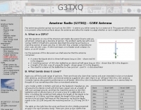 Review by G3TXQ and comparison to its modificated versions. SWR Measurements on inverted V setup and comparison from EZNEC model and a real one.
 -
 The Coaxman by Clear Signal Products, Inc. features a complete Wireman line of coaxial cable and antenna wire. Antenna wire, baluns, coax connectors, insulators, ladder line, magnet wire, rope.
 -
 With over 20 years of experience, Proyecto 4 operates as a specialized ham radio retailer in Madrid, Spain, providing a diverse inventory of transceivers, antennas, and related accessories. The store features popular models like the _ICOM IC-705_ and _ICOM IC-7300MK2_, alongside Yaesu transceivers such as the _FTX-1 Optima_, which delivers 100W on HF and 50W on V/UHF bands. The product range includes mobile and portable antennas, such as the D-Original DX-NR770HB, offering 3 dB gain on 144 MHz and 5.5 dB on 430 MHz, and the Diamond RH-770 with a BNC connector. CB radio enthusiasts can find the Anytone CB SMART II AM/FM transceptor and the Telecom LS145 mobile antenna, rated for 500W and 4 dB gain on 26-30 MHz. Proyecto 4 emphasizes its in-house technical service, inviting customers to visit their laboratory for repairs and technical consultations via sergio@proyecto4.com. The store also highlights customer reviews and offers promotions like Yaesu Cashback, providing savings up to 100€.