Search results
Query: 1 GHz
Links: 138 | Categories: 4
-
 OH3TR operates the OH3SHF microwave beacons on 2.3, 3.4, 5.7, 10 and 24 GHz
 -
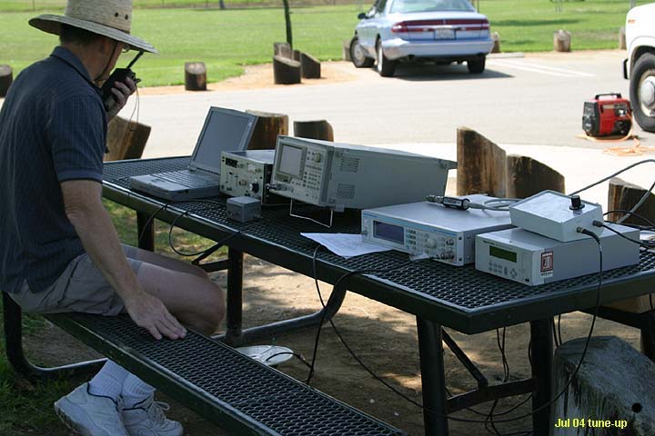
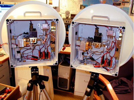
 Developing operational amateur radio equipment for the 134 GHz band presents significant technical challenges, particularly in frequency generation and stability. This resource details the construction of a 134 GHz system, outlining its architecture with separate transmit (Tx) and receive (Rx) modules, each employing a local oscillator (LO) and RF head units. The system utilizes a dual Flann 50 GHz lens-type horn antenna configuration for optimal signal coupling. The transmit path incorporates an LMX2541 synthesizer chip operating at approximately 2.8 GHz, referenced by a 10 MHz double-oven Morion OCXO for exceptional stability. This signal is multiplied through a series of stages (X4, then X2) to generate a 22.4 GHz signal, which subsequently drives a dual series diode multiplier to produce the final X6 signal for 134 GHz operation. The receive side features an anti-parallel diode mixer coupled to a 144 MHz transceiver via a preamplifier, ensuring effective downconversion. Operational mode is CW, achieved by keying a multiplier stage. The project includes images of the Tx and Rx head units and describes a successful 3.5 km test with G8ACE, demonstrating stable signal tones due to PLLs locked to OCXOs at both ends, confirming the system's robust performance.
 -
 Tecom industries product line encompasses a wide range of highly sensitive active and passive antennas for use in airborne and ground applications, providing complete coverage of the 20 MHz to 40 GHz frequency range.
 -
 The world's oldest beacon OZ7IGY in JO55WM 28 MHz to 24 GHz.
 -
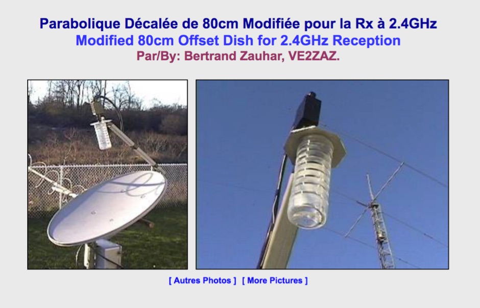 Modified 80cm Offset Dish for 2.4 GHz Satellite Reception. This 50-ohm impedance antenna allows, when connected to 2.4GHz preamplifier and downconverter, to receive Amateur satellites with 2.4GHz transponders such as AO-40.
 -
 The San Bernardino Microwave Society, operating under the callsign _W6IFE_, serves as a significant technical hub for amateur radio operators specializing in frequencies above 1 GHz. This organization's influence extends across Southern California, providing a centralized resource for advanced RF experimentation and **regional frequency management** within the microwave spectrum. Its permanent value lies in its extensive archive of technical papers and project documentation, which are critical for operators engaged in high-frequency design and deployment. The society's infrastructure is primarily intellectual, focusing on the dissemination of specialized knowledge rather than a conventional repeater network. It offers a robust collection of technical papers from prominent members like K6PIP, K6BLG, and WA6EXV, covering topics such as Rubidium oscillator data, logging software, and filter design. This resource facilitates advanced amateur radio operations, including participation in microwave contests and the development of custom transverters for bands like 24 GHz. The site also details various member projects, such as the Owens Valley Radio Observatory Project, showcasing practical applications of **RF propagation analysis** and system integration. DXZone Focus: Microwave | Technical Papers | RF Propagation | Contest Results
 -
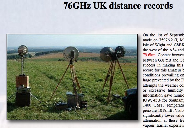 Successful two way contacts were made on 75976.2 MHz covering a distance of 79.6km and in years later 129 Km
 -
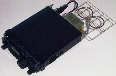
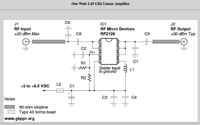
 Bi-Directional 2.4 GHz One Watt Amplifier With Receive Pre-Amplifier. This will show you how to add a bi-directional, 2.4 GHz amplifier to your Proxim Symphony for under $100
 -
 Demonstrates MegaPhase's extensive product line of RF and microwave coaxial cable assemblies and components, engineered for demanding applications up to 110 GHz. Key offerings include _Test & Measurement Cables_ with superior phase and amplitude stability, _RF & Microwave Cables_ utilizing _GrooveTube®_ technology for high power systems, and a range of RF components like directional couplers and power dividers. The site details specific cable types such as _Alumibend™_ for space-qualified, ultra-light applications through 90 GHz, and armored cables designed for rigorous environments up to 50 GHz, emphasizing their robust mechanical strength and measurement repeatability. The resource highlights applications across diverse sectors, including space programs like the _Hayabusa_ mission, global security (C5ISR), military airborne systems (MIL-T-81490), telecom, and automated testing. It also provides technical insights through "How To" guides on measuring amplitude/phase stability vs. flexure and proper connector cleaning. The company's commitment to quality is underscored by its rigorous testing protocols and a strong warranty, ensuring reliable operation in critical systems.
 -
-
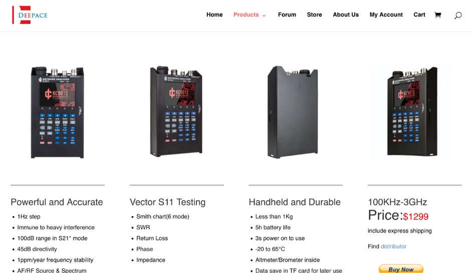 KC901S Handheld vector antenna analyzer RF ANALYZER 3GHz S11 S21 Fieldmeter RF Source Spectrum
 -
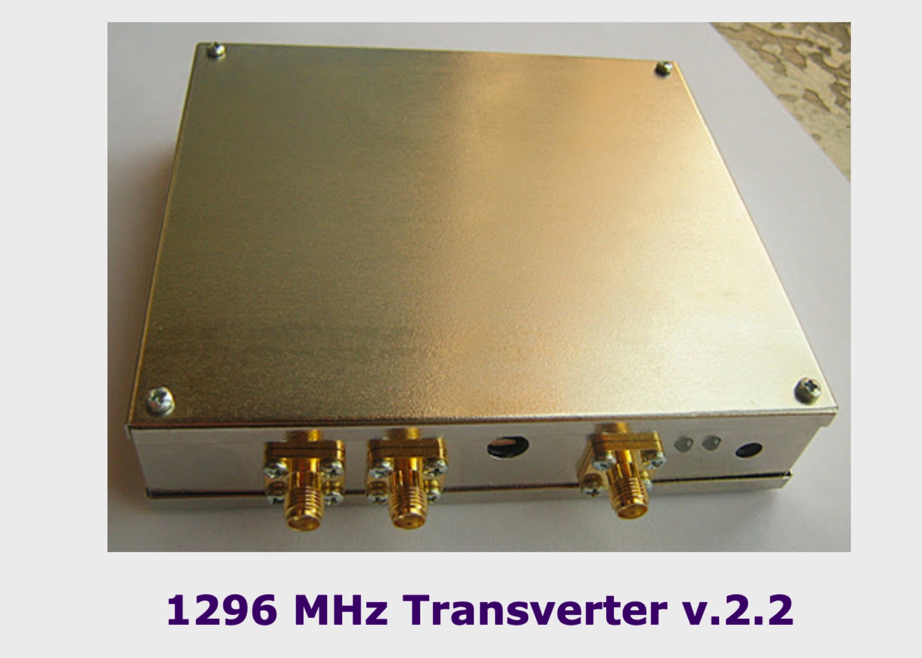 Transverter for 13 cm 23 cmd and 33 cmd band. 23 cm RF power amplifier, RF power amplifier for 2.4 GHz for the QO-100 satellite. Popular for the 1296 MHz transverter
 -
 Offers a range of high-performance RF interconnect solutions, addressing the critical need for reliable signal integrity across diverse radio frequency applications. Their product line includes custom cable assemblies, various **RF connectors** (such as SMA), adapters, and terminators, designed to meet stringent specifications from DC up to 40 GHz. These components are essential for maintaining low insertion loss and excellent VSWR in demanding environments, from test benches to operational communication systems. The company specializes in providing tailored solutions for both commercial and government sectors, emphasizing precision manufacturing in Warner Robins, Georgia. Their offerings are crucial for engineers and operators requiring specific lengths, connector types, and performance characteristics for their radio equipment and test setups. Ensuring robust connections and protection against transient voltage events, their **surge protectors** are integrated into systems to safeguard sensitive electronics from damage, a common concern in outdoor or high-power installations.
 -
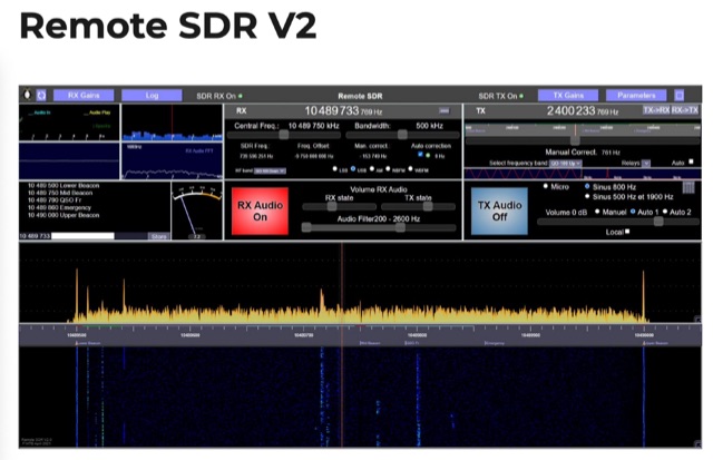 Remote SDR is a web application allowing to remotely control an amateur radio transceiver between 1 MHz and 6 GHZ. It allows processing of Adalm-Pluto SDR in addition to HackRF or RTL-SD Reception in NBFM, WBFM, AM in addition to SSB Transmission in NBFM or SSB and more
 -
 High Speed Multimedia (HSMM) radio, as introduced by John Champa, K8OCL, represents a significant advancement in amateur radio's digital capabilities, moving beyond traditional keyboard modes like packet radio. This initiative, driven by ARRL's Technology Task Force, focuses on developing high-speed digital radio networks capable of up to 20 megabits per second. HSMM primarily facilitates digital voice (DV) and digital video (ADV), enabling real-time video transmission from emergency scenes to an EOC without expensive ATV gear, often requiring only a laptop, a PCMCIA card, a digital camera, and a small antenna. The working group's initial efforts concentrate on cultivating microwave skills within the amateur community to build and support portable and fixed high-speed radio-based local networking, or **RLANs**. These networks prove invaluable for RACES and ARES organizations, as well as homeland security and other emergency communications. Field Day exercises and simulated emergency tests (SETs) are encouraged to hone skills in rapid site surveys and deploying broadband HSMM microwave radio networks, with examples like linking Field Day logging stations or antenna test results at the Midwest VHF-UHF Society Picnic 2003. Getting started with HSMM often involves adapting off-the-shelf **IEEE 802.11** (WiFi) equipment to comply with amateur radio regulations, typically operating in the 2.4 GHz ISM bands. While consumer WiFi gear has range limitations under Part 15 rules, proper setup under amateur regulations can extend coverage significantly, with test networks like the Hinternet achieving 5-15 mile ranges at 54 M bit/s using small mast-mounted dish antennas. Careful selection of equipment with external antenna ports, high transmit power, and low receive sensitivity is crucial, along with using low-loss coaxial cable like LMR-400 for optimal performance at these frequencies.
 -
 A very small receiver converter that can be plugged to the backside of the battery powered portable transceiver FT817 from Yaesu. A high performance receiver for 2.3GHz amateur radio signal
 -
 Microwaves101 provides an extensive repository of information covering fundamental principles of microwave design, targeting engineers and radio amateurs interested in the higher frequency spectrum. The site features a detailed _encyclopedia_ of microwave terms and concepts, alongside practical design considerations for various components and systems. It serves as a foundational reference for understanding RF propagation, transmission lines, and active/passive microwave circuits. The resource includes numerous calculators for impedance matching, filter design, and other critical RF parameters, facilitating hands-on project development. Discussions on **10 GHz** equipment and **24 GHz** projects highlight practical amateur radio applications, extending to operations up to 134 GHz. Content spans from basic theory to advanced topics like MMIC design and antenna characteristics, supporting both educational and practical endeavors in microwave technology.
 -
 This will show you how to add a RF power amplifier to your Proxim Symphony for under $50. The cost is reduced by using the existing components on the Symphony, such as the PIN diode switch, and just inserting a higher power final amplifier. Increase the RF output power of your wireless network card to 1 Watt.
 -
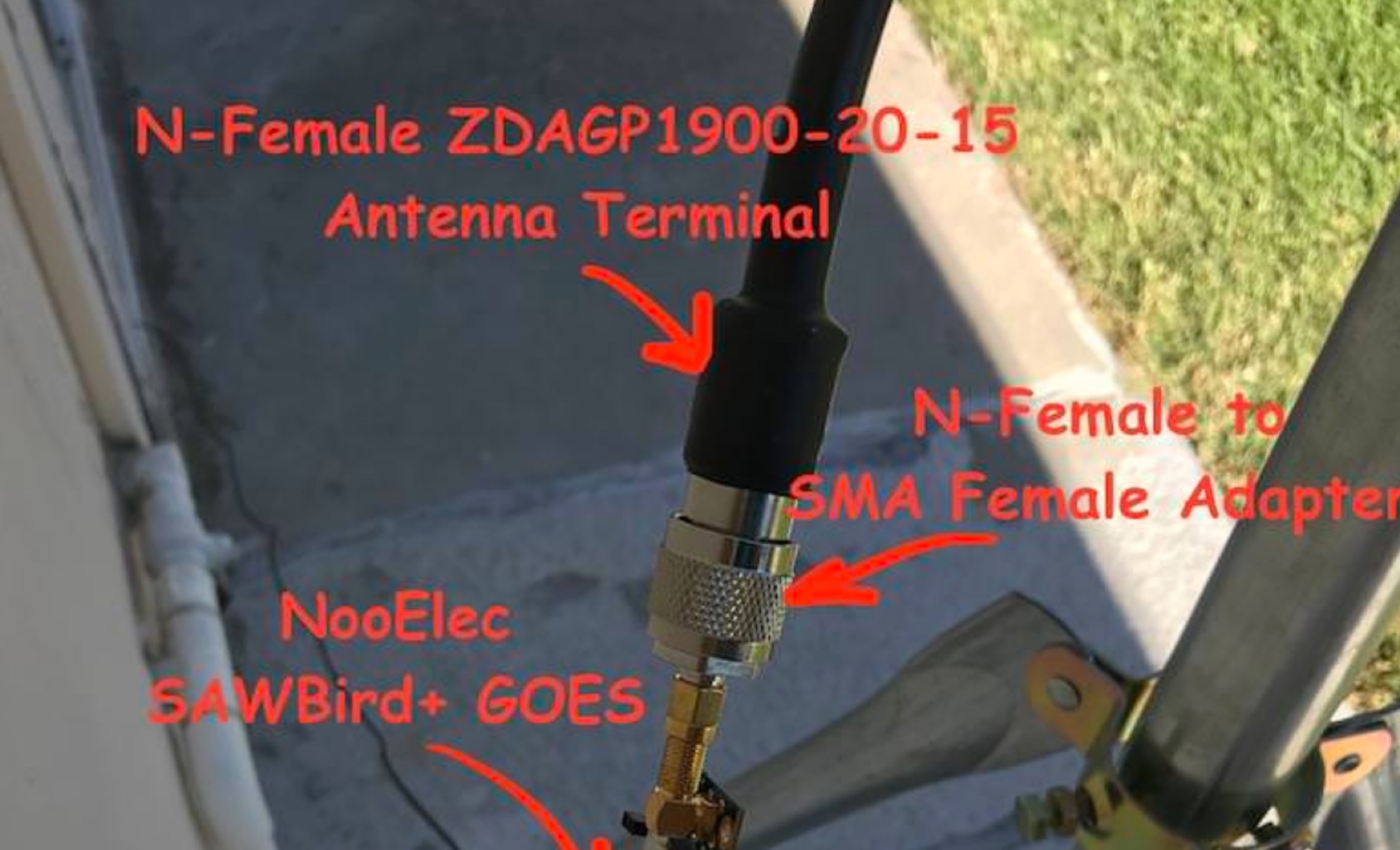 Receiving **GOES-16** and **GOES-17** weather satellite imagery requires a specific hardware and software configuration, detailed in this practical guide. The author outlines the necessary components, including a Raspberry Pi, an RTL-SDR dongle, a suitable LNA with SAW filter for 1.69 GHz, and a parabolic grid antenna. This setup enables direct reception of high-resolution weather data, a fascinating aspect of amateur radio satellite operations. The installation process begins with preparing the Raspberry Pi, followed by updating the system and installing essential dependencies like `git`, `build-essential`, and `cmake`. A critical step involves compiling and installing `librtlsdr` from source, ensuring proper driver setup and blacklisting conflicting DVB drivers. The guide then walks through testing the RTL-SDR dongle to confirm device recognition and troubleshoot common issues like USB power or driver installation problems. Finally, the instructions cover cloning and building `goestools`, a software suite essential for processing the satellite signals. This compilation, while time-consuming on a Raspberry Pi, is crucial for decoding the raw data into usable imagery. The guide concludes with the initial steps for creating the `goesrecv.conf` configuration file, preparing the system for active satellite reception.
 -
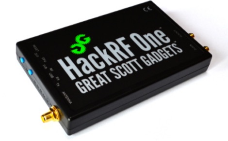 open source hardware for software-defined radio. HackRF One is an open source hardware platform that can be used as a USB peripheral or programmed for stand-alone operation. 1 MHz to 6 GHz operating frequency
 -
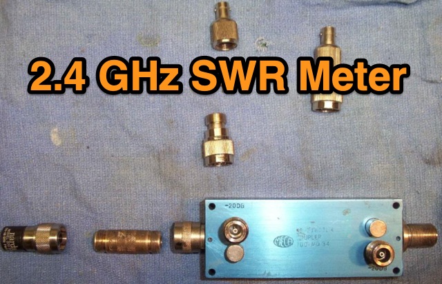 This is a simple 2.4 GHz SWR meter which is based around surplus microwave hardware which can be easily found. The main component is a MECA -20/-20 dB Directional Coupler which has a frequency range of approximately 700 MHz to 2.5 GHz.
 -
 Modification to an old cellular phone base station modules, with a fairly reduced output power (10 watts or so), the stock power amplifier modules will cover the 2.3 GHz and 2.4 GHz amateur radio bands.
 -
 Nuand bladeRF 2.0 Software Defined Radio (SDR) 47MHz to 6GHz, 2x2MIMO, 61.44MHz sampling
 -
 When building antennas for the Wifi band (Like the 8dBi omni), a need for an easy way to check the antennas arose. A Voltage Standing Wave Ratio (VSWR) meter useable at the 2.4GHz band is however, hard to find.
 -
 The article describes the construction of a 1:49 impedance transformer designed to match the high impedance (around 2500Ω) of an end-fed half-wave (EFHW) dipole antenna to the 50Ω impedance of a typical transceiver. The EFHW is a popular portable antenna due to its simple construction, but feeding it can be challenging compared to a center-fed dipole. The transformer was built using an FT240-43 ferrite toroid core, with 2 primary and 14 secondary windings for a 1:49 impedance ratio. A capacitor was added in series with the primary winding to improve performance at higher frequencies. The author compared versions with one and two cores, and found that 100pF worked best for the single core design while 200pF was optimal for the dual core transformer.
 -
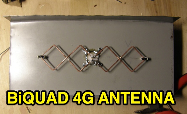 This is basic instructions for homemade 4G Antenna working on 2600 MHz UMTS featuring 13 14 dBi gain. This antenna is desigend to resonate on microwave frequencies in two segments from 2500 to 2570 MHz for Uplink, and from 2620 to 2690 MHz for Downlink.
 -
 This Satellite Antenna Elevation System project involves mounting horizontally polarized Yagi antennas on a fiberglass reinforced polymer (FRP) crossboom. A Yaesu G-800DXA azimuth rotator is in place, requiring only an elevation rotation system. Elevation is controlled by a 12VDC linear actuator connected to a U-bolted arm on the crossboom, rotating within a DIY bearing arrangement. Common handyman tools suffice for assembly. The setup includes FRP crossboom, aluminum tubing, PVC couplers, nylon camshaft bushes, and a K3NG-based controller for azimuth and elevation control. Detailed guides and resources are available online.
 -
 Microwave Filter Company is a leader in the design, development and manufacture of high quality passive electronic filter products in the 5 Hz to 50 GHz frequency spectrum.
 -
 A DIY cantenna can extend your WiFi range by building a 2.4 GHz high-gain antenna using accessible materials. The design, based on waveguide principles, uses a cylindrical tube to capture WiFi signals and can even connect to access points half a mile away in ideal conditions. While the ideal tube diameter was hard to find, a 4-inch aluminum dryer vent was chosen despite theoretical limitations. The cantenna offers a cost-effective, functional boost for your wireless network.
 -
 The most basic form of repeater receives communication on one frequency and re-transmits it on a different frequency, a process known as duplex communication. This capability significantly extends the range of handheld and mobile radios, as repeaters are typically situated at elevated locations with high-gain antennas and greater transmit power. Repeaters commonly operate with FM modulation on the VHF (30 MHz – 300 MHz) and UHF (300 MHz – 3 GHz) amateur bands, which are ideal for portable and mobile devices. Access to repeaters is often controlled by a CTCSS or PL tone, an inaudible signal that prevents the repeater from retransmitting background noise. This mechanism ensures efficient use of the frequency and prevents illegal continuous transmission. Canadian regulations, for instance, require an Advanced amateur radio license and an available frequency within the band to set up a repeater, each assigned a unique call sign and transmit frequency. Configuring a radio for repeater use involves knowing the repeater's transmit frequency, its receive frequency offset (e.g., -600 KHz for VHF or +5 MHz for UHF), and the necessary CTCSS tone. The article references resources like Repeater Book for locating repeaters and provides practical examples for initiating and concluding a basic repeater session, emphasizing clear identification and concise communication.
 -
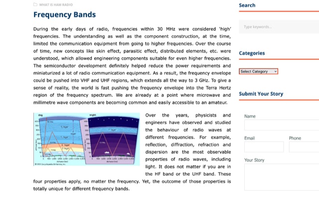 During radio's early days, high frequencies were under 30 MHz due to technical limitations. As understanding grew, components improved, allowing for higher frequencies like VHF and UHF up to 3 GHz. The HF band's long wavelengths provide unique propagation challenges influenced by solar activity. VHF and UHF bands face diffraction and reflection issues but offer diverse applications, from amateur radio to 5G and GPS technologies.
 -
 A UHF Frequency Counter up to 1 GHz, includes the Block Diagram , test sketch for Arduino/Genuino Nano
 -
 Manufacturer of 50MHz, 70MHz, 144MHz, 222MHz, 432MHz, 900MHz or 1.2GHz transverters and VHF UHF amplifiers
 -
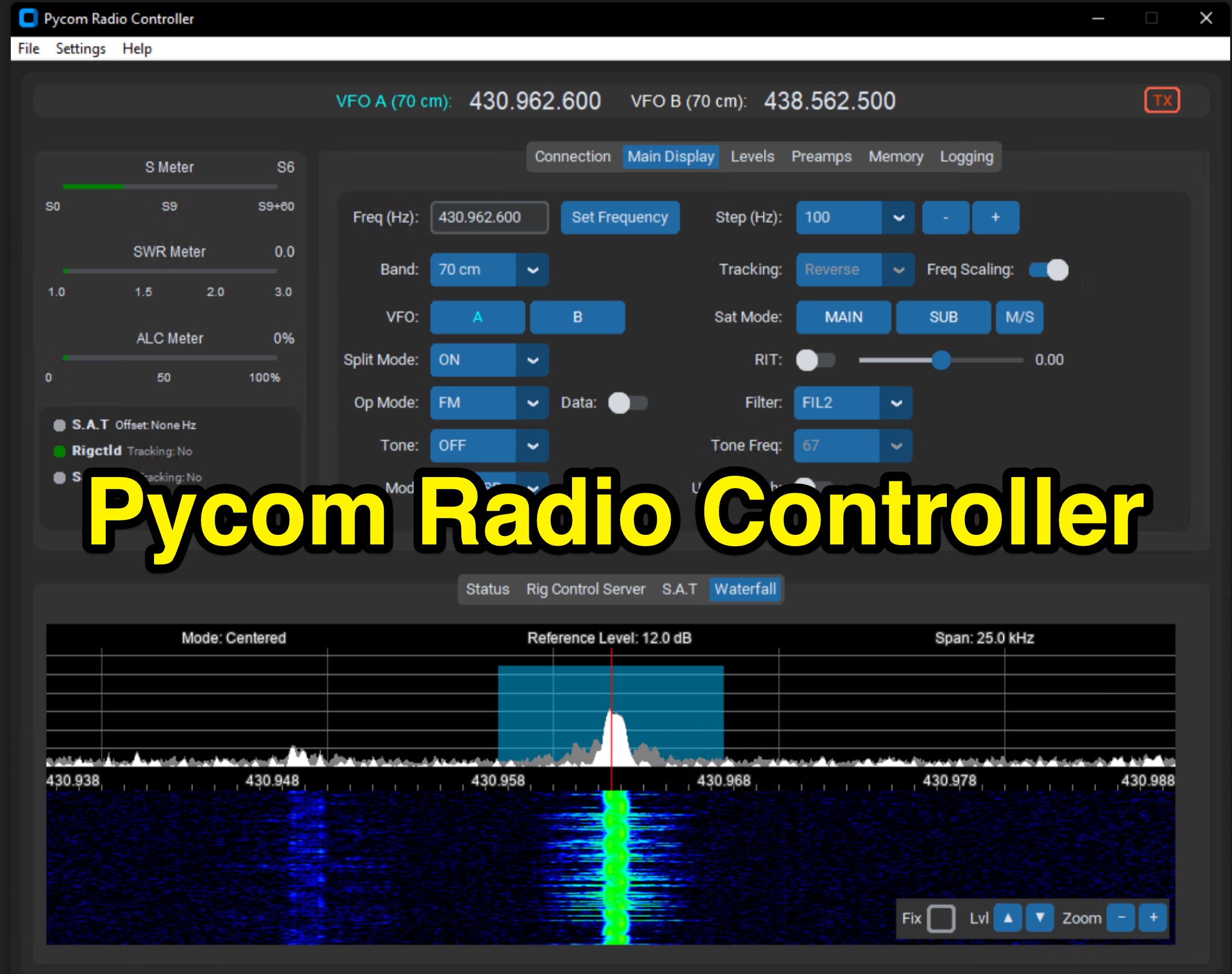 The Icom IC-9700 transceiver, a popular choice for VHF/UHF/1.2 GHz operations, gains enhanced remote control capabilities through Pycom Radio Controller. This software provides direct _CI-V based control_, enabling operators to manage frequency, mode, memories, and tones from a connected computer. It integrates a built-in rigctl server and supports popular satellite tools like Gpredict and SatPC32, facilitating full duplex Doppler control for satellite passes. Key features include real-time meters, a waterfall display, and remote RC-28 integration. Designed for practical amateur radio use, the application streamlines voice and digital satellite operations. It allows for full duplex remote Doppler control, crucial for maintaining accurate frequencies during satellite contacts. The software also incorporates callsign lookup and logging functions, alongside enhanced memory management. Documentation pages offer configuration guidance and operating examples, ensuring users can effectively set up and utilize the software for their satellite communication needs, potentially improving success rates for contacts and contests.
 -
 In this project by building a W2IMU feed horn, the author successfully optimized their 10GHz Small Dish EME project. To position and solder the components together, they used a jig and a conical section made of copper sheet. Stability was ensured by fitting the XLNA to the WG switch. The WG components were shod into a waterproof plastic container, and the feed horn and WG were surrounded by a collar and skirt that were 3D printed. With an average Moon noise of 0.5dB, the Sun and Moon noise readings were better than their previous configuration.
 -
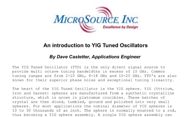 The YIG Tuned Oscillator (YTO) is the only direct signal source to provide multi octave tuning bandwidths in excess of 10 GHz. Common tuning ranges are from 2-10 GHz, 8-18 GHz and 10-20 GHz. YTO is are also known for their superior phase noise and exceptional tuning linearity.
 -
 The Meshtastic documentation outlines critical LoRa configuration parameters for node operation, emphasizing regulatory compliance. It details settings such as Region, Modem Preset, Max Hops, Transmit Power, Bandwidth, Spread Factor, Coding Rate, and Frequency Offset. A comprehensive table provides region codes, frequency ranges (e.g., US **902.0 - 928.0 MHz**), duty cycles, and power limits (e.g., EU_433 **12 dBm**) for numerous countries, including the US, EU, China, and Japan, alongside a 2.4 GHz band option. It explicitly states that devices within a mesh must share identical _Region_ and _Modem Preset_ settings for full communication. Modem Presets, like _LONG_FAST_ (the default), optimize for either speed or range, directly impacting network congestion and message delivery delay. For instance, SHORT_TURBO offers the fastest speed and shortest range, while VERY_LONG_SLOW provides the longest range but is less reliable for mesh formation. The document also highlights specific duty cycle limitations, such as the 10% hourly limit for EU_433 and EU_868 regions, and provides command-line interface (CLI) examples for configuring these parameters.
 -
 This online construction guide details the assembly of a signal generator specifically for the **13cm band** (2.4 GHz). The curriculum focuses on the integration of a Voltage Controlled Oscillator (VCO), specifically the ROS-2400, to produce a stable RF signal. The resource outlines the necessary components for frequency generation and output, including the use of a Mini-Circuits MMIC amplifier for signal conditioning. The construction protocol involves configuring the ROS-2400 VCO to operate within the 2.3 GHz to 2.45 GHz range, ensuring frequency coverage for amateur radio _microwave experimentation_. The guide specifies the output power level, approximately 70mW, directly from the MMIC stage, indicating its application as a low-power instrumentation source rather than a transmit-capable device. This project provides a practical example of constructing a dedicated test instrument for microwave frequency measurements and system alignment on the **13cm band**. DXZone Focus: Construction Guide | 13cm Signal Generator | VCO Integration | Microwave Experimentation